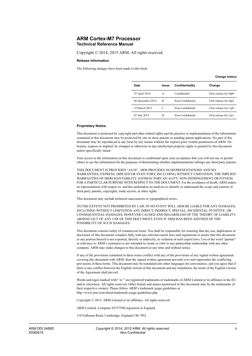
ARM Cortex-M7 Processor Technical Reference Manual
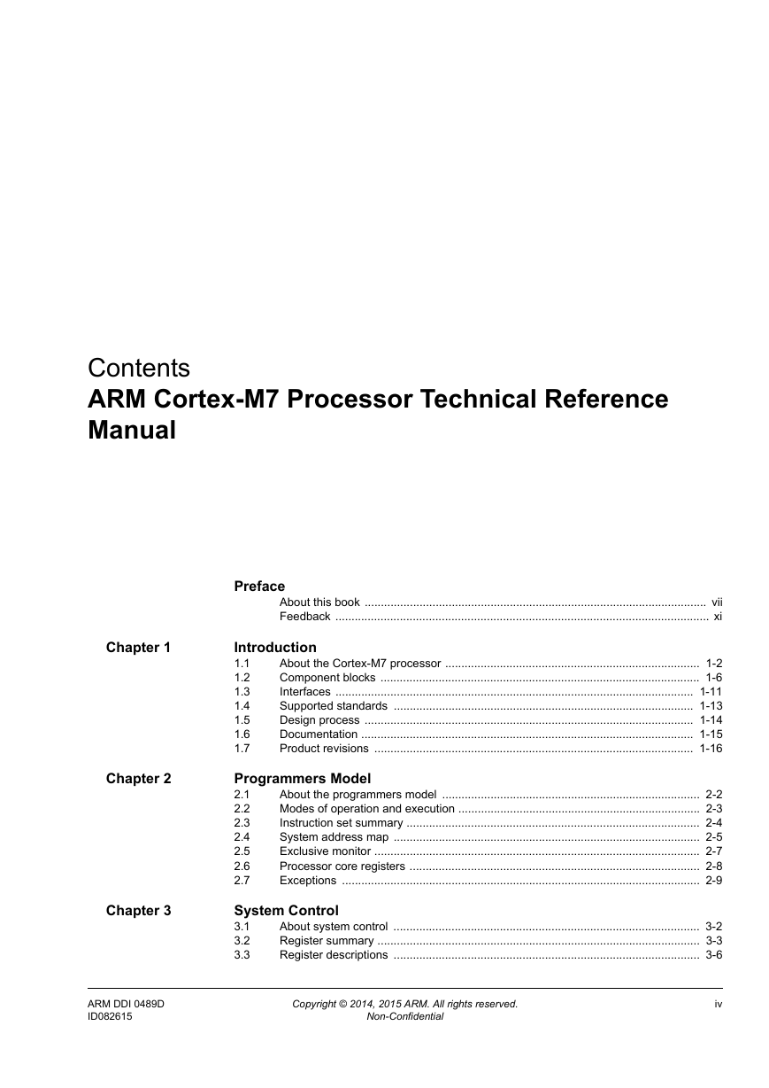
Contents
Preface
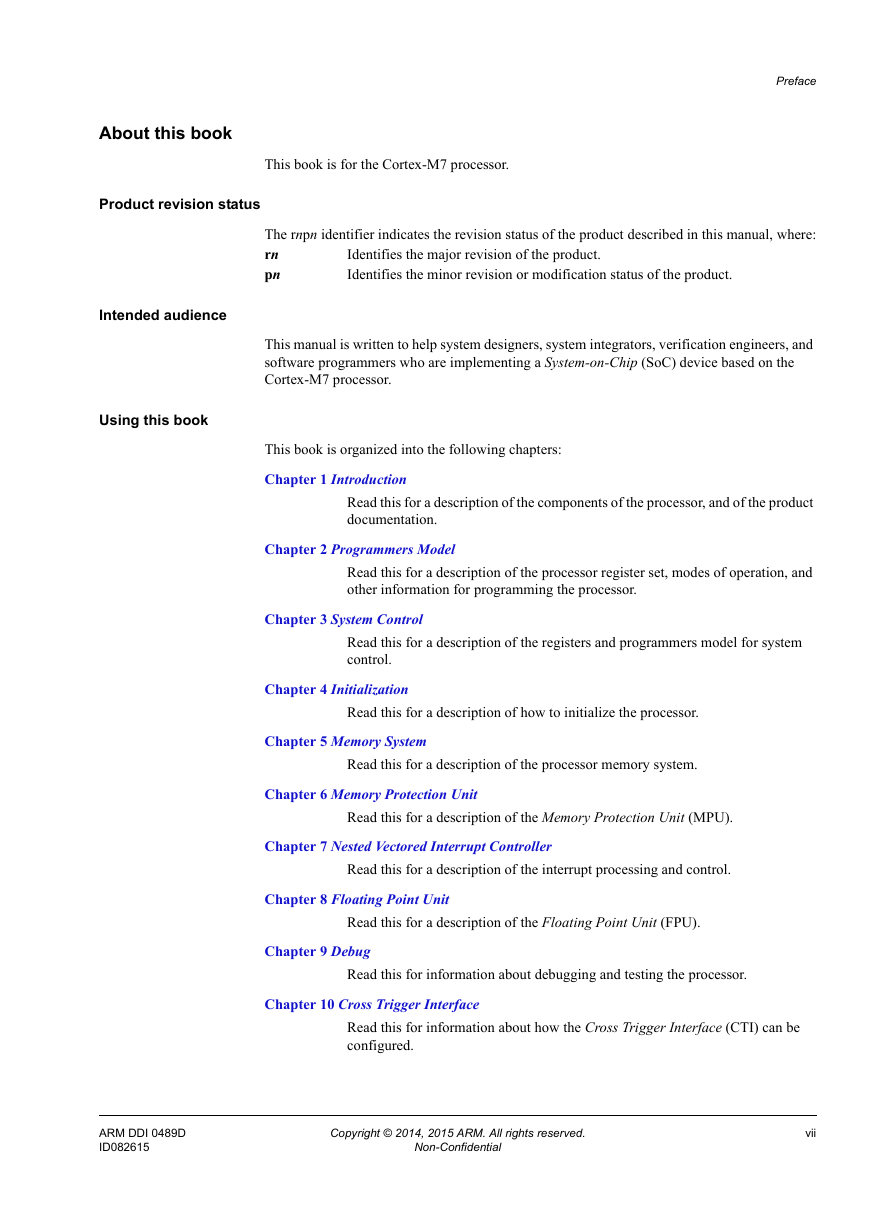
About this book
Product revision status
Intended audience
Using this book
Glossary
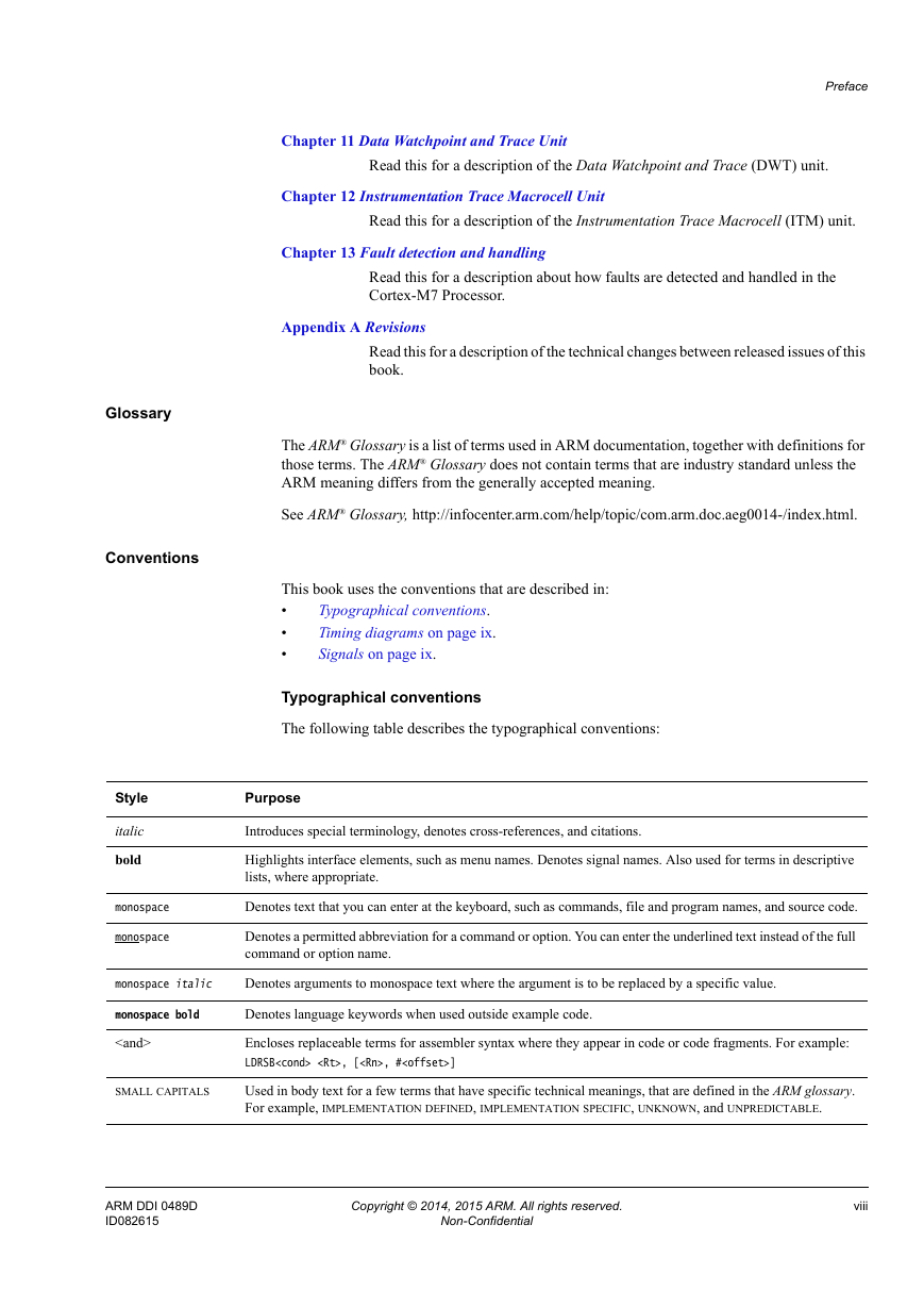
Conventions
Additional reading
Feedback
Feedback on this product
Feedback on content
1: Introduction
1.1 About the Cortex-M7 processor
1.1.1 Features
1.1.2 Interfaces
1.1.3 Configuration options
1.2 Component blocks
1.2.1 Data Processing Unit
1.2.2 Prefetch Unit
1.2.3 Load Store Unit
1.2.4 Floating Point Unit
1.2.5 Nested Vectored Interrupt Controller
1.2.6 Wake-up Interrupt Controller
1.2.7 Memory System
1.2.8 Store Buffer
1.2.9 Memory Protection Unit
1.2.10 Cortex-M7 Processor and PPB ROM tables
1.2.11 Cross Trigger Interface Unit
1.2.12 ETM
1.2.13 Debug and trace components
1.3 Interfaces
1.3.1 AHBP interface
1.3.2 AHBS interface
1.3.3 AHBD interface
1.3.4 External Private Peripheral Bus
1.3.5 ATB interfaces
1.3.6 TCM interface
1.3.7 Cross Trigger interface
1.3.8 MBIST interface
1.3.9 AXIM interface
1.4 Supported standards
1.4.1 ARM architecture
1.4.2 Bus architecture
1.4.3 Debug
1.4.4 Embedded Trace Macrocell
1.4.5 Floating Point Unit
1.5 Design process
1.6 Documentation
1.7 Product revisions
2: Programmers Model
2.1 About the programmers model
2.2 Modes of operation and execution
2.2.1 Operating modes
2.2.2 Operating states
2.2.3 Privileged access and unprivileged User access
2.3 Instruction set summary
2.3.1 Binary compatibility with other Cortex processors
2.4 System address map
2.4.1 Private peripheral bus
2.4.2 Unaligned accesses that cross regions
2.5 Exclusive monitor
2.6 Processor core registers
2.7 Exceptions
2.7.1 Exception handling
3: System Control
3.1 About system control
3.2 Register summary
3.3 Register descriptions
3.3.1 Auxiliary Control Register
3.3.2 CPUID Base Register
3.3.3 Cache Level ID Register
3.3.4 Cache Size ID Register
3.3.5 Cache Size Selection Register
3.3.6 Instruction and Data Tightly-Coupled Memory Control Registers
3.3.7 AHBP Control Register
3.3.8 L1 Cache Control Register
3.3.9 Auxiliary Bus Fault Status Register
3.3.10 Instruction Error bank Register 0-1
3.3.11 Data Error bank Register 0-1
3.3.12 AHB Slave Control Register
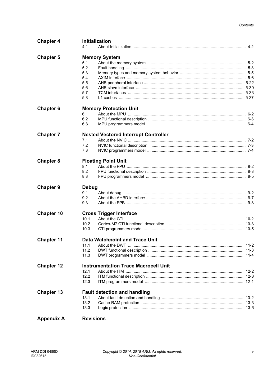
4: Initialization
4.1 About Initialization
4.1.1 Initializing the MPU
4.1.2 Initializing the FPU
4.1.3 Initializing and enabling the L1 cache
4.1.4 Disabling cache error checking and correction
4.1.5 Enabling the TCM
4.1.6 Preloading TCM
4.1.7 Enabling the TCM retry and read-modify-write
4.1.8 Enabling the AHBP interface
5: Memory System
5.1 About the memory system
5.2 Fault handling
5.2.1 Faults
5.2.2 Usage models
5.3 Memory types and memory system behavior
5.4 AXIM interface
5.4.1 AXI attributes and transactions
5.4.2 Identifiers for AXIM interface accesses
5.4.3 AXI privilege information
5.4.4 Write response
5.4.5 AXI extensions
5.4.6 Memory system implications for AXI accesses
5.4.7 AXIM interface transfers
5.5 AHB peripheral interface
5.5.1 AHBP interface transfers
5.5.2 AHBP semaphores
5.6 AHB slave interface
5.6.1 Memory map
5.6.2 Restrictions on AHBS transactions
5.6.3 AHBS interface arbitration
5.7 TCM interfaces
5.7.1 TCM attributes and permissions
5.7.2 TCM configuration
5.7.3 TCM arbitration
5.7.4 TCM interface protocol
5.7.5 TCM read modify write
5.7.6 Booting from TCM
5.7.7 Integration with Flash memory
5.7.8 System access to TCM
5.8 L1 caches
5.8.1 Dynamic read allocate mode
5.8.2 Store buffer
5.8.3 Cache maintenance operations
5.8.4 Cache interaction with memory system
6: Memory Protection Unit
6.1 About the MPU
6.2 MPU functional description
6.3 MPU programmers model
7: Nested Vectored Interrupt Controller
7.1 About the NVIC
7.2 NVIC functional description
7.2.1 Low power modes
7.2.2 Level versus pulse interrupts
7.3 NVIC programmers model
7.3.1 Interrupt Controller Type Register
8: Floating Point Unit
8.1 About the FPU
8.2 FPU functional description
8.2.1 Modes of operation
8.2.2 Compliance with the IEEE 754 standard
8.2.3 Exceptions
8.3 FPU programmers model
9: Debug
9.1 About debug
9.1.1 Cortex-M7 Processor ROM table identification and entries
9.1.2 Cortex-M7 PPB ROM table identification and entries
9.1.3 System Control Space
9.1.4 Debug register summary
9.2 About the AHBD interface
9.3 About the FPB
9.3.1 FPB functional description
9.3.2 FPB programmers model
10: Cross Trigger Interface
10.1 About the CTI
10.2 Cortex-M7 CTI functional description
10.3 CTI programmers model
11: Data Watchpoint and Trace Unit
11.1 About the DWT
11.2 DWT functional description
11.3 DWT programmers model
12: Instrumentation Trace Macrocell Unit
12.1 About the ITM
12.2 ITM functional description
12.3 ITM programmers model
12.3.1 ITM Trace Privilege Register
13: Fault detection and handling
13.1 About fault detection and handling
13.1.1 RAM and logic protection
13.1.2 Analysis of errors
13.2 Cache RAM protection
13.2.1 Protection method
13.2.2 RAM protection summary
13.2.3 ECC codes
13.2.4 RAM configuration
13.2.5 Performance impact
13.3 Logic protection
A: Revisions


 2023年江西萍乡中考道德与法治真题及答案.doc
 2012年重庆南川中考生物真题及答案.doc
 2013年江西师范大学地理学综合及文艺理论基础考研真题.doc
 2020年四川甘孜小升初语文真题及答案I卷.doc
 2020年注册岩土工程师专业基础考试真题及答案.doc
 2023-2024学年福建省厦门市九年级上学期数学月考试题及答案.doc
 2021-2022学年辽宁省沈阳市大东区九年级上学期语文期末试题及答案.doc
 2022-2023学年北京东城区初三第一学期物理期末试卷及答案.doc
 2018上半年江西教师资格初中地理学科知识与教学能力真题及答案.doc
 2012年河北国家公务员申论考试真题及答案-省级.doc
 2020-2021学年江苏省扬州市江都区邵樊片九年级上学期数学第一次质量检测试题及答案.doc
 2022下半年黑龙江教师资格证中学综合素质真题及答案.doc