第 1l卷 第 1期
2011年 2 月
Journal of Transportation Systems Engineering and Information Technology
February 201 1
交通 运 输 系统工 程 与信 息
V01.11
NO.1
文 章 编 号 : 1009—6744 (2011)01—0061—12
Variable-Bandwidth Progression O ptim ization in Traffi c Operation
HU Pei—feng ,TIAN Zong—zhong ,YUAN Zhen—zhou , JIA Shun—ping
(1.Department of Civil& Environmental Engineering,University of Nevada,Reno,NV ,USA 89557
2. School of Traffic and Transportation,Beijing Jiaotong University,Beijing 1 00044,China)
Abstract: Attempts are often made to find an optim al coordinated control plan for a group of traffi c signals
in urban areas,such that platoons of vehicles can proceed through a continuous series of green lights without
stopping,thereby.reducing considerable unnecessary delay. One main objective of coordinated control is to
provide the maximum bandwidth progression by adliusting the offset and phase sequence pattern for each sig—
nalized intersection. M ost models and methods currently being used are based on mixed—integer linear pro—
gramming (MILP), which is a mathematical optimization model originally formulated by Little et a1.in
1966. A basic limitation of the M ILP is that it adds a large num ber of com plex constraints for traffic control
networks. In this paper, a new simple m ethod is introduced for finding the optim ization plan of arterial and
network control by maxim ization of variable bandwidth. This method has not any ”loop’’ constraints and a
completely new approach eompares to the M ILP method applied in this field. In addition,the results of two
examples this paper provided validity and feasibility of this new approach in real applications of traffic signal
coordinati0n contro1.
K ey w ords: traffic engineering;traffi c control;variable bandwidth progression; offset; NEM A phase se—
quence pattern
CLC num ber: U491.51
D ocum ent code: A
交 通 运 行 管 理 中 的 可 变 绿 波 带 优 化
胡佩峰 ,田宗忠 ,袁振 洲 ,贾顺平
(1.美 国 内华 达 大 学 雷 诺 分 校 土 木 与 环 境 工 程 系 ,雷 诺 89557,美 国 ;
2.北 京 交 通 大 学 交 通 运 输 学 院 ,北 京 100044)
摘 要 : 在 城 市 交通 控 制 中 ,很 多 研 究 尝 试 为 多 个 信 号 交 叉 口 设 计 最 优 的 协 调 控 制 方
案 ,从 而 使 得 车 队 在 通 过 多个 交 叉 口 时 能 够 获 得 一 系 列 连 续 的 绿 灯 信 号 ,无 需 停 车 、不
间断地 运行 ,这 样 可减 少一 些 不 必要 的停 车延误 时 间 ,而这 种停 车 延误 在现 实 中往 往 比
较 可 观 .此 类 协 调 控 制 的 主 要 目标 之 一 是 获 取 最 大 绿 波 带 ,通 过 调 整 各 个 交 叉 口 之 间
的相 位 差 以及各 个 交 叉 口本 身 的相序 来 实现 . 目前在 实际 中得 到 应 用 的有 关模 型和 方
法 大 多是 以 混 合 整 数 规 划 为 基 础 的 一 种 线 性 最 优 化 模 型 ,最 早 由 Little等 人 于 1966年
提 出.这 种 模 型 的 基 本 局 限 性 在 于 ,对 于 面 控 系 统 ,需 要 引 入 数 量 众 多 的 复 杂 约 束 .本
文 提 出 了一 种 新 型 简 便 的 最 优 化 方 法 ,通 过 最 大 化 可 变 绿 波 带 实 现 对 干 线 和 网 络 各 信
号 交 叉 口的 最 优 协 调 控 制 .从 应 用 范 围 来 看 ,该 方 法 与 混 合 整 数 规 划 方 法 的 不 同 点 在
于 规 避 了 对 实 施 协 调 控 制 的 道 路 网络 的 封 闭 性 要 求 ,因 而 是 一 种 全 新 的 方 法 .此 外 ,本
文 还 利 用 2个 实例 对 该 方 法 在 交 通 信 号 协 调 控 制 中 的 有 效 性 和 实 用 性 进 行 了验 证 .
关 键 词 : 交 通 工 程 ;交通 控 制 ;可 变绿 波 带 ;相 位 差 ;NEMA 相 位 系 列
中 图 分 类 号 : U491.51
文 献 标 识 码 : A
收 稿 日期 :2010-07—26 修 回 日 期 :2010—1 1—10 录 用 日 期 :2010—12—01
作 者 简 介 :胡 佩 峰 (1981一),男 ,博 士 生 .
通 讯 作 者 :zongt@unr.edu
�
62
交 通 运 输 系 统 工 程 与 信 息
2011年 2月
1 Intl oduction
model in 1996. called “M ULTIBAND 一 96”。 which
The main objective of coordinated traffic signal
could optimize all the signal control variables in a net—
control is to keep traffic progressing in a platoon m ini—
work. During the same period, the Texas Transporta—
mizing delays or stops throughout the signal system .
tion Institute developed “PASSER IV ”, a personal
Through proper synchr0nization of signal timing along
com puter—based program for optimizing signal timings
arterials or urban networks,coordinated control plans
for arterials and multi--arterial closed—-loop net--
can effectively reduce stops,delays and excessive fuel
works[…
. Currently.many researchers are continu—
consumption. Two main m ethods have been used to a—
ing to research this topic; however, most recent en—
chieve this objective.The first is based on total delay
deavors have tried to improve the effi ciency of these
minimization in the signal system l 一
, and the other
models through the help of different m athematical al-
focuses on bandwidth maxim ization along an arteri—
gorithms【 一
. Particularly. genetic algorithm s com —
a1t , ]
. Severa1 other researchers have combined the
bined with the M ILP are the m ost popular method of
delay m inim ization and bandwidth maximization mod—
finding the optimal solution fo r coordinated traffi c sig—
els to obtain an optimal solution for coordinated signal
nal tim ing plans along arterials or in networks.
system s[ 一
. The methodology presented 、in this pa.
This paper presents a new approach to obtain the
per achieves an optim al traffi c signal control plan by
optim al solution by determ ining the critical variables
maximizing total weighted bandwidth of the traffic sig—
of coordinated signal control, such as NEM A phase
nal system .Thus,the following literature review fo cu—
sequence patterns and offsets. This new approach is
ses on research and documents pertaining to band—
easy to follow and can be implem ented using common
width maxim ization.
computer programming languages,such as C ,C ++ ,
In 1966. Little et a1.[5 3 first presented a mathe—
Visual Basic,et a1. The rem ainder of this paper is
matical bandwidth maxim ization model, called the
composed of three sections. Following this introduc·
mixed—integer linear program (MILP) mode1. Their
tion,the first section introduces the new optimization
synchronization method produced two possible results:
approach.The second section provides two typical ex—
(1)the biggest possible bandwidth of equal size for
amples to demonstrate the practical applicability of
both directions of an arterial,and (2) favoring one
the proposed approach. At last, conclusions are
direction of an arterial with a large bandwidth and
drawn regarding the proposed approach based on the
then finding the best possible bandwidth in the oppo—
analysis results from the examples.
site direction,if feasible. Based on this model,Little
et 。1.【lo 3 developed a new mode1 ca11ed ” M AX—
2 M ethodology
BAND ” which could yield a global optimal solution,
Coordinated traffi c signal control is a strategy to
finding cycle time, offsets, and NEM A phase se—
provide a smooth flow of traffic along arterials and net—
quence patterns to maximize the weighted com bination
works,reducing travel times, stops, and delays. Co—
of the bandwidths in both directions along an arteria1.
ordinated signal systems operate most effi ciently when
In 1988. Chang et a1.[… extended this m odel to a
traffic volumes between adjacent intersections are
new version called “M AXBAND 一 86” which could
heavy and signalized intersections are in proxim ity to
oDtim ize mu1ti arteria1 networks. Gartner e nZ.[12]
each other. W hen traffic between each signalized in—
presented an optim ization approach for arterial pro—-
tersection can maintain a good platoon structure, co—
gression that could generate variable bandwidth in
ordination of the signals will be m ore—beneficia1. In
which each directional road segm ent obtained an indi—
cases where traffi c volumes are low and vehicles arrive
vidually weighted bandwidth fo r different traffi c vol—
at a signal randomly,or when signals are suffi ciently
um e scenarios between intersections. Based on this
separated, then coordinated signal control operations
approach,Stam atiadis and Gartne developed a new
may provide few distinct benefits[
.
�
第 11卷 第 1期
Variable—Bandwidth Progression Optimization in Traffic Operation
63
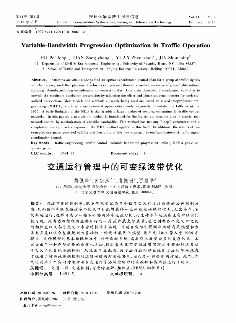
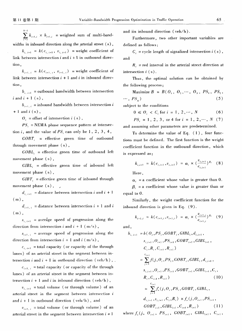
Time—space diagram s are a com monly used tool
the signal phases at an intersection, including the
to depict the quality of signal tim ing and progression.
green time plus any change interva1. The cycle length
A tim e—space diagram of three intersections is shown
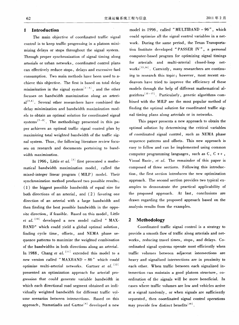
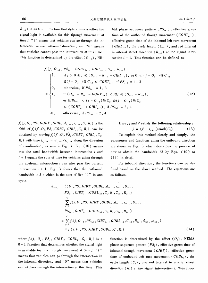
in Fig.1,and the associated NEM A phase sequence
patterns are shown in Fig. 2. In Fig.1, the cycle of
of each signalized intersection should be equal to (or
an exact multiple of)the minimum cycle time of all
一厂 一厂 一厂 9
;妻
一
鼢
signals in the coordinated control system .
each intersection is the same though their green tim e
(2)Split of a phase.
intervals along arterials are different. Assume out—
W ithin a cycle, split of a phase is the portion of
bound direction is from intersection 1 to 3, and in—
tim e allocated to each phase at a signalized intersec—
bound direction is the opposite. Bandwidth 1 2 in
tion. In this paper,the split of a phase is measured
Fig.1, which is the bandwidth between intersection 1
by seconds and are considered as the effective green
and 2 in the outbound direction,is greater than Band—
tim e fo r the phase.
width 23. Additionally, the offset reference point is
(3)NEMA phase sequence pattern.
the end of the barrier on the side street. Thus, the
NEMA phase sequences used in this paper are
offset of intersection 1 is zero,and the offset of inter—
NEM A phase sequences, which employ a ‘‘dual ring
section 2 and 3 is shown in Fig.1. In Fig.2, four
concurrent” timing process and predetermined phase
NEMA phase sequences along the arterial are shown
order to label the operation sequence for each individ—
clearly, whereas not shown for crossing streets.
ual movem ent at the signalized intersection. Fig. 2
(1)Cycle length.
indicates the four possible patterns of NEM A phase
Cycle length is the total signal time to serve all
sequences that are analyzed in this paper.
融
■
§《…
…
£j蛆 g《§≥ 。
l §捧 《__ _ _目 _一
i
…
…
《 l 0《《《 ∞
…
…
《 ∞
≈
E ∞ ∞■ ■ ■ ■ ■ 嘲
nbcm喇
D~ ctcn
。
,
、
∽
ii &■日 鬻%舔 l2g§ §《鞲
… ; ∞∞ l jj聪豳
;
\
… … …
一
■ g_ 口 __ ∞口一
%舞 以 《g l
§ ■ ■_——— 一
。翩
L蝴 ∞ d:
cy~Io1
cycI92
Time
cycI。3
Cycle4
曩蚕墨ii 曩 Grei~THm For琢 嘲la}1触 婚m0m
曩嚣 G潞辅 TimeForLoll Tum Movernent Outbound Direct~
曩曩 譬鬣 蓦翟露 Gre9n T;m0 For L磅囊 Tum Movement-n lnbound Dtreaion
Fig.1 Time space diagram of a coordinated traffic signal control plan
(4)Offset reference point.
and the system m aster clock,which is defined as that
The offset reference point is a specified point that
point within a cycle in which the local controller’s
creates an association between the local signal clock
offset is measured relative to the m aster clock. In this
�
64
交通 运 输 系统 工 程 与 信 息
2011年 2月
nalized intersection to achieve the maximum band—
width. The cycle length and split optimizations are not
covered in this study.
2.1 Arterial coordination m odel
To develop a multi..bandwidth m odel fo r an arte..
rial street.the basic objective funotion and severa1
variables must first be introduced.The basic objective
is to find the maximum weighted sam of multi--band--
width in both directions through finding the offset and
NEM A phase sequence pattern of each signalized in—
tersection. A com prehensive search is used for maxi.
mizing the objective function in this paper.To consid-
er the problem more generally,assum e there are a to-
—
—
—
—
—
—
—
ain Artery— ———— ——— + 一 Cross Street—
l—
One Cycle ———————————————————
’ 。 ‘ 。 。 。 。 。 。 。 。 。 。 。 。 。 。 。 。 。 。 。 。 。 。 。 ’
。 ’ —
— T im e —— —————————— — —— ‘ — —‘——一 。 。。 ’ 。’一
Fig.2 Four possible NEM A phase sequence patterns
ta1 of N signalized interseetions with two directions of
with overlap
travel at each intersection.The objective function is
paper,the offset reference point is defined as a point
that the end of barrier on the main street,or the start
of any phase(through phase or left phase)in arterial
street direction (Fig.1).
(5)Offset.
The term offset that is dependent on the offset ref-
erence point,is used for controlling the start time refer—
ring to the master controller.The offset ranges from zero
to the cycle length of the signalized intersection. Offset
is a critical parameter to determ ine the effect of coordi—
nation in signalized intersections(Fig.1).
(6)Bandwidth.
defined as:
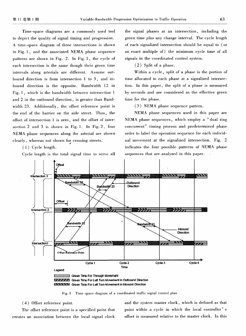
B =B(0l,02,… ,0Ⅳ,P5l,PS2,… ,PJsⅣ)(1)
=
∑
‘
+
一
(2)
¨∑
= ∑ (Ci,i+l, +。)×6(0 ,PS ,GOBT ,
×
6
GIBL ,d
十
.
+l ,s
. + l , 0 +l,
+
PS +I,GOBT +l,GIBL +I,C ,R ,13 +l,R +1)
¨∑
+ k(c… . , … . )x b(0 ,PS ,
+
GIB Ti,GOBL ,d +1
×
6
,8 +I
.
; ,
0 +l,P5 +l,
.
十
GIB T + ,GOBL +.,C ,R ,C
;+ 。 ,R +,) (3)
Bandwidth is described as the am ount of green
time available for vehicles to travel through a system
N 一 1
= ∑ [ (c … +.)×6(0 ,PS ,
E J
at a determined progression speed. Each direction on
GOBT ,GIBL ,d +I,s
. + l ,
0 +l,
the arterial street has its own bandwidth. Bandwidths
PS +J,GOBT +l,GIBL +l,C ,R ,C +,,R +1)
in the same direction in a street can vary between ad—
+ (c .
,
. )x b(0 ,PS ,G1BT ,
jacent signalized intersections.To suinmarize,there
GOBL ,d +1
5 +I
,
.
.
i ,0 l,P 。+l,
are four principal signal timing parameters for deter—
GIBT +。,GOBL +.,C ,R ,C +。,R +。)] (4)
mining the optimal solution of coordinated traffic sig—
where,
nal contro1.which are as follows:
(a)Cycle length.
(b) Green time splits of each phase.
(e)NEMA phase sequence.
(d)Offsets.
This study focuses on determining the optimal
B(0.,02,… ,0Ⅳ,PsI,P52,… ,PsⅣ! =ob—
jective function,which is a function of variables:O1,
O2,… ,OⅣ,PSl,PS2,… ,PSⅣ(s)and which is the
weighted suIn of multi—bandwidth in both directions,
N —l
∑k +i×b +I=weighted sum of multi—bandwidths
l 1
NEMA phase sequence pattern and offset of each sig—
in outbound direction along the arterial street(s),
�
第 11卷 第 1期
Variable—Bandwidth Progression Optimization in Traffic Operation
65
∑ k…, ×b…, =weighted sum of multi—band—
and iin inbound direction (veh/h).
Furthermore, two other important variables are
widths in inbound direction along the
,a~efial street(s),
defined as follows:
k【If+l= (c +l, +1) =weight coefficient of
C :cycle length of signalized intersection i(s),
link between interseetion i and i十 1 in outbound direc—
and
tion ,
R : red interval in the arterial street direction at
= (c… . ,
… . ) =weight coefficient of
.
intersection i(s).
link between intersection + l and i in inbound direc—
Thus, the optimal solution can be obtained by
tion ,
the following process:
b
,
+I =outbound bandwidth between intersection
Maximize B = B(0.,02,… ,0 ,PS.,PS2,
i and i+ 1 (s),
…
, PS )
(5)
b +l = inbound bandwidth between intersection i
subject to the conditions
+ 1 and i(s),
O,:offset of intersection i(s),
PS = NEM A phase sequence pattern at intersec—
tion i,and the value of PS can only be 1,2,3,4 ,
GOBT = effective green tim e of outbound
through movement phase(s),
0 ≤ O < C for i= 1,2,… ,N
(6)
PS
,
= 1,2,3,or 4 for i= 1,2,… ,N (7)
and assum ing other param eters are predetermined.
To determine the value of Eq. (1),four rune—
_呈
tions must be defined. The first function is the weight
m
H d
d
coeffi cient function in the outbound direction, which
GOBL = effective green tim e of outbound left
is expressed as:
movement phase(s),
GIBL = effective green time of inbound left
川 = k(ci
i+l ~Vi
,
,
e 出
i+ 1)
× (
(8)
movement phase(s),
Here,
n n
C .
GIB T = effective green tim e of inbound through
oL : a coeffi cient whose value is greater than 0.
O
movement phase(s), ,
卢 =a coefficient whose value is greater than or
.一 . 础
+1 = distance between intersection i and i+ 1
equal to 0.
d
.
(111),
d +1
.
= distance between intersection i+ 1 and i
(m),
|三 . _吾
毗
O
s。。+I = averdge speed of progression along the
direction from intersection i and i+ 1(m/s),
and,
ki+l
i =
C i+I
i~Vi+I
,
,
,
i)
×(
r
(9)
吐
e
5 +l = average speed of progression along the
b…+l=b(0 ,JPS ,GOBT ,GIBL ,d +I,
direction from intersection i+ 1 and i(m/s),
s +l,0 +l,PS +J,GOBT +l,GIBL +l,
c +l:total capacity(or capacity of the through
C ,R ,C +.,R +1)
lanes)of an arterial street in the segment between in—
C i十1
tersection i and i+ 1 in outbound direction (veh/h),
: ∑f(J,0 ,PS ,GOBT ,GIBL—d, ,
c +I :total capacity(or capacity of the through
lanes) of an arterial street in the segment between in—
tersection i+ l and i in inbound direction (veh/h),
v +J=total volume (or through vohllIle)of aI1
arterial street in the segment between intersection i
and i+1 in outbound direction (veh/h),and
=total volume (or through volume)of an
s +l,0 +1,尸S +l’GOBT +1,GIBL +1,C ,
R ,C ,R )
c i+i
(10)
= ∑fo( ,0 ,PS ,GOBT ,GIBL ,
d +,~s… ,C ,R )×fo( ,0 ,PS… ,
GOBT + ,GIBL + ,C +.,R + )
(11)
arterial street in the segment between intersection i+ 1
where ( ,o ,P5… ,GOBT… ,GIBL… ,C… ,
�
R +1)is an 0~1 function that determines whether the
MA phase sequence pattern (PS… ),effective green
交 通 运 输 系 统 工 程 与 信 息
2011年 2月
signal light is available for this th
rough movement at
.
time of the outbound though movement(GOB T… ),
time j.“1”means that vehicles can go through the in—
effective green tim e of the inbound left turn movement
tersection in the outbound direction.and “0’’ means
lI
(GIBL… ),the cycle length(C… ),and red interval
that vehicles cannot pass the intersection at this time.
.
This function is determined by the offset(O… ),NE—
.n
D ,
¨
, ,
in arterial street direction(R )at the signal inter—
,
section i+ 1. This function can be defined as:
, PS ,GOBT… ,GIBL… ,C… ,R… )
ifJ > 0&J≤ (0 一R… 一GIBL ),or 0 < (J一0 )% C…
&( 一 0 )% C ≤ GOBTi+。,if PS… = 1,3
otherwise,if PS +l = 1,3
if(0 + 一R +l— GOBT +。) < & ≤ (O 。一R。+。),
(12)
or GIBL < (J一0 )% C &(J~0 )% C
≤ (GOBTi+i+GIBL ),if PS… =2,4
otherwise,if PS +l = 2,4
(J_,0f,P|s ,GOBT ,GIBL ,d +J s… ,C ,R )is the
Here,J and J satisfy the following relationship:
shift offo(J ,0i,PSf,GOBT ,GIBL ,C ,R ) can be
J= (J +t + )mod(C )
(13)
obtained by movingfo(J ,0 ,P ,GOBT ,GIBL ,C ,
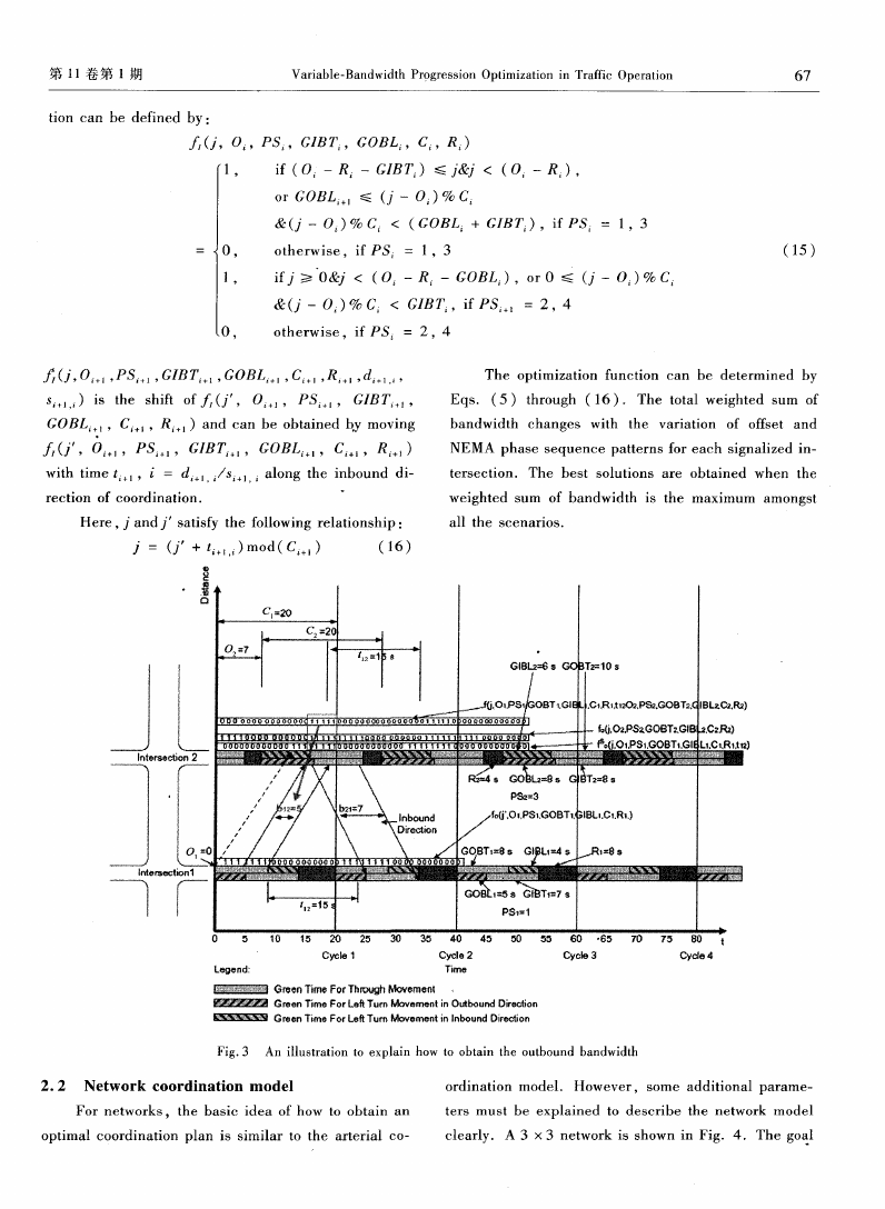
To explain this m ethod clearly and sim ply, the
R )with time t +l= d +l/s +l along the direction
parameters and functions along the outbound direction
of coordination,as seen in Fig.3.Eq.(10)means
are shown in Fig. 3 which describes the process of
that the total bandwidth between jntersection i and
how to obtain the bandwidth 12 by Eqs. (10) to
i+ 1 equals the sum of time for vehicles going through
(13)in detail.
the upstream intersection i can also pass the current
For inbound direction,the functions can be de-
intersection i + 1. Fig.’3 shows that the outbound
fined based on the ahove method. The equations are
bandwidth is 5 s which is the SHill of five “1” in one
as follows:
cycle.
d +,
,
: b(0 ,PS ,GIBT~,GOBL ,d +).
s +,
.
,
,
0 +,,
PS +l,GIBT +,,GOBL。+ 。 ,C ,R ,C +l,R +I)
C
= ∑f(J,0 ,PS ,GIBT ,GOBL—d+I. ,Si+l,i,0 ,
J=1
PS +l,GIBT +l,GOBL +l,C ,R ,C +l,R +1)
ci
= ∑A(J,o川,PS ,GIBT…,GOBL -,C ,R ~d I.1,s ,。)
』 1
x (J,0 ,Ps ,GIBT ,GOBL ,C ,R )
(14)
where ( ,0 ,PJs。,G1BT ,GOBL ,C ,R )is a
function is determined by the offset(O ),NEMA
0 — 1 function that determ ines whether the signal light
phase sequence pattern(PS:),effective green time of
is available for this through nlovenlent at time “1”
inbound though movement 0 GlBTi ,effective green
means that vehicles can go through the intersection in
the inbound direction。 and “0” m eans that vehicles
cannot pass through the intersection at this time. This
time of outbound left turn movement(GOBL ),the
cycle length (C ),and red interval in arterial street
direction(R )at the signal intersection i.This func—
�
t
第 11卷 第 1期
0
n
C
a
n
b
e
d
e
r 己=
e
d
{
.,
Variable—Bandwidth Prggression Optimization in Traffic Operation
67
D ,
PS ,GIBT ,GOBL ,C ,R )
1,
if(0 一R 一 GIBT ) ≤ & < (O 一R ),
or GOBL… ≤ (J一0 )% C
&( 一0 )% C < (GOBL +GIBT ),if PS = 1,3
0,
otherwise,ifPS = 1,3
(15)
1,
ifJ≥ 0 < (0 一R 一GOBL ),or 0 ≤ (J一0 )% C
&( 一0 )% C < GIBT;,if PS : 2,4
otherwise, ifPS = 2,4
(J,0… ,Ps ,GIBT ,GOBL ,C ,R ,d ,
The optim ization function can be determined by
s…
. ) is the shift of (J , 0… , P5 , GIBT… ,
Eqs.(5)through (16).The total weighted sum of
GOBL +l,C l,R 1)and can be obtained by moving
bandwidth changes with the variation of offset and
(J ,0 ,PS ,GIBTi+ ,GOBL ,C ,R )
NEMA phase sequence patterns for each signalized in—
with tim e t。+ l , i = d +J
.
/s +1
.
along the inbound di—
terseetion. The best solutions are obtained when the
rection of coordination.
。
weighted snm of bandwidth is the m aximum am ongst
Here,J and J satisfy the following relationship:
all the scenarios.
J = (J +t . )rood(C )
(16)
l
· 量
0
Inl erseoti m 2
、
r
CI=20
I—
=20
‘
l
1
.}
‘2篁 r —l
孽T笋 10 s
..o, p。 。BT惦 L C,.R,l12 +PS2.GoBT2 l8L2 Rz
一
Oz.PSzGOBT2。GIB j.C2。Pa)
6 O1,PSi GOBTt.GI{ L1 t.R’“
鳓}l黼一——霸翻
/,
{
G鑫L2礴。G eT2礴8
PS==3
/
D, /
l ~rsectj on1
\ tnbo盛u ndn/ /f。 Ol。P8t.GOBT1.I ;,IBLI et.R1 j
/ /
G0BTI=8$ Gt~.bt=4 s
}l
-/
嚣 薯薯誊《g嚣 ∞瓣 #∞
, ___目__l
‘
8 8
§ g§
《 _日__目一
E E《 《 #饕藿g# 。 ——一
∞ ■ $§《
《 __口__一
I一
.1
tl 2=15{ I
GOB 8 G国lT r1=7g
PS~=I
Legend:
Cycle
Cycle2
Time
Cycle3
G-~de4
蕊翟麓
露嚣露露2§ 翟 G拇en Time For LeftTurn Movement in Outbo und Direction
Green Tim口For Through Mov@ment 一
蕊 整 四 Green T|me For LeftTurn Movement in Inbound Direction
Fig.3 An illustration to explain how to obtain the outbound bandwidth
2.2 Netw ork cO0rdinati0n m odel
ordination mode1. However, some additional parame—
For networks,the basic idea of how to obtain an
ters m ust be explained to describe the network model
optimal coordination plan is sim ilar to the arterial CO—
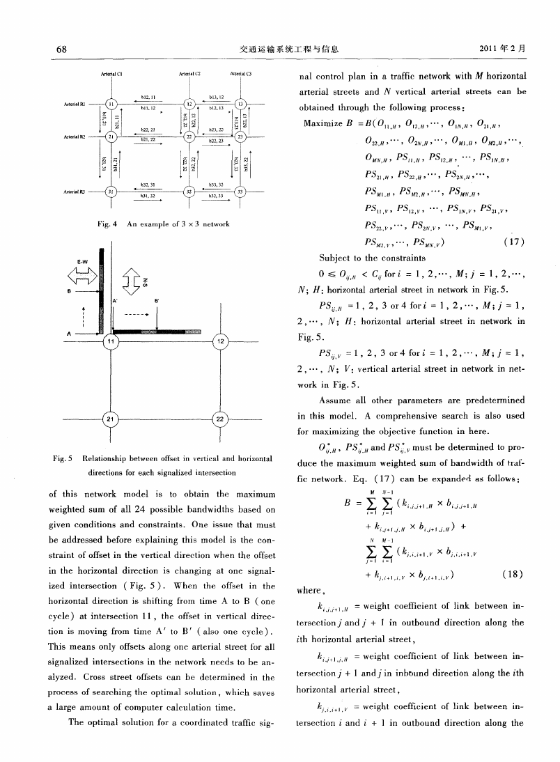
clearly. A 3 × 3 network is shown in Fig. 4. The goa1
�
68
交 通 运 输 系 统工 程 与 信息
2011年 2月
nal control plan in a traflfie network with M horizontal
arterial streets and N vertical arterial streets can be
obtained through the following process:
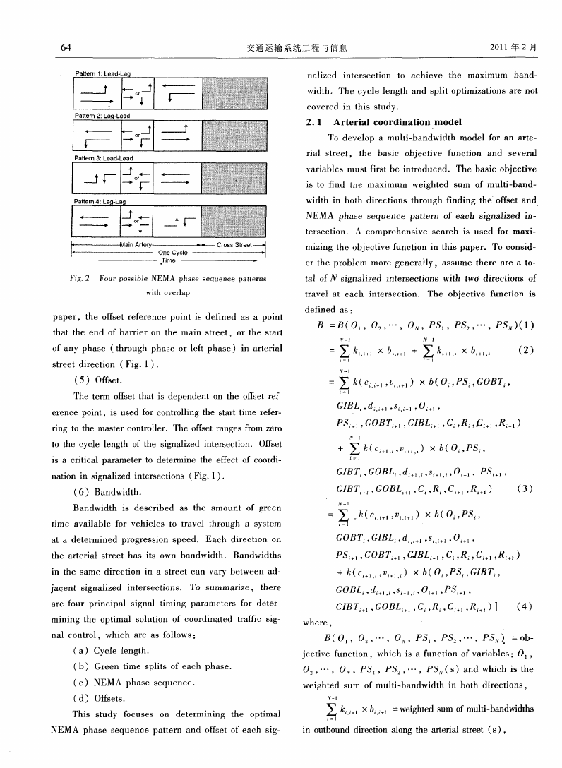
Maximize B =B(01l,
H , 0l2
.
Ⅳ,… ,0lⅣ
. H , 02l
, H ,
022
H,… ,02Ⅳ
,
.
…
,
, 0肘l
, H , 0肼2
.
H , …
,
Fig.4 An example of 3 ×3 network
OMN H,Psn H,Psl2 H}… ,Ps1N H,
PS21
. H ,
PS22
月,… ,PS2Ⅳ
.
.
…
,
,
Psm ,PS H,… ,PSMN H,
P5l1
.
PSl2
,
,
…
,
, PSlⅣ
, P52l
,
.
,
P 22
,
, …
, PS2Ⅳ
, …
,
JPSMi
,
.
,
PSm
…
,
.
,
)
(17)
Subject to the constraints
0 ≤ 0
H < C for i= 1,2,… , ;J_= 1,2,… ,
,
N H :horizontal arterial street in network in Fig.5.
PS = 1,2,3 or 4 for i= 1,2,… ,M ; = 1,
2,… ,N ; H :horizontal arterial street in network in
Fig.5.
PS ,
.
= 1,2,3 or 4 for i=1,2,。一,M ;J:1,
2,… ,N ; :vertical arterial street in network in net-
work in Fig.5.
Assume all other parameters are predetermined
in this m ode1. A com prehensive search is also used
for maximizing the objective function in here.
o ,PS; H and Ps v must be determined to pro。
duce the maximum weighted sum of bandwidth of traf-
tic network.Eq. (17)can be expanded as follows:
∑ “
, \ ∑ 川
+
Fig.5 Relationship between offset in vertical and horizontaI
directions for each signalized intersection
of this network model is to obtain the maximum
M Ⅳ 一 l
weighted sum of all 24 possible bandwidths based on
B=∑ ∑ (k Ⅷ ×b 。,
I i J = 1
given conditions and constraints. One issue that m ust
+ k 'j Ij’H x bl,J l i H +
be addressed before explaining this model is the con—
straint of offset in the vertical direction when the offset
in the horizontal direction is changing at one signal—
x bJ
, ‘, + l,
ized intersection (Fig.5). When the offset in the
where,
horizontal direction is shining from time A to B (one
cycle)at intersection 1 1,the offset in vertical direc—
tion is moving from time A to B (also one cycle).
This means only offsets along one arterial street fo r all
signalized intersections in the network needs to be an—
k..i.i“ H = weight coefficient of link between in—
tersection 3 and 3+ 1 in outbound direction along the
ith horizontal arterial street,
k
J+l,』, = weight coefficient of link between in—
,
alyzed. Cross street offsets can be determined in the
tersection +1 and j in inbound direction along the th
process of searching the optimal solution,which saves
horizontal arterial street,
a large amount of computer calculation tim e.
十1. = weight coefficient of link between in—
,
The optimal solution for a coordinated traffic sig—
tersection i and i + 1 in outbound direction along the
�


 2023年江西萍乡中考道德与法治真题及答案.doc
 2012年重庆南川中考生物真题及答案.doc
 2013年江西师范大学地理学综合及文艺理论基础考研真题.doc
 2020年四川甘孜小升初语文真题及答案I卷.doc
 2020年注册岩土工程师专业基础考试真题及答案.doc
 2023-2024学年福建省厦门市九年级上学期数学月考试题及答案.doc
 2021-2022学年辽宁省沈阳市大东区九年级上学期语文期末试题及答案.doc
 2022-2023学年北京东城区初三第一学期物理期末试卷及答案.doc
 2018上半年江西教师资格初中地理学科知识与教学能力真题及答案.doc
 2012年河北国家公务员申论考试真题及答案-省级.doc
 2020-2021学年江苏省扬州市江都区邵樊片九年级上学期数学第一次质量检测试题及答案.doc
 2022下半年黑龙江教师资格证中学综合素质真题及答案.doc