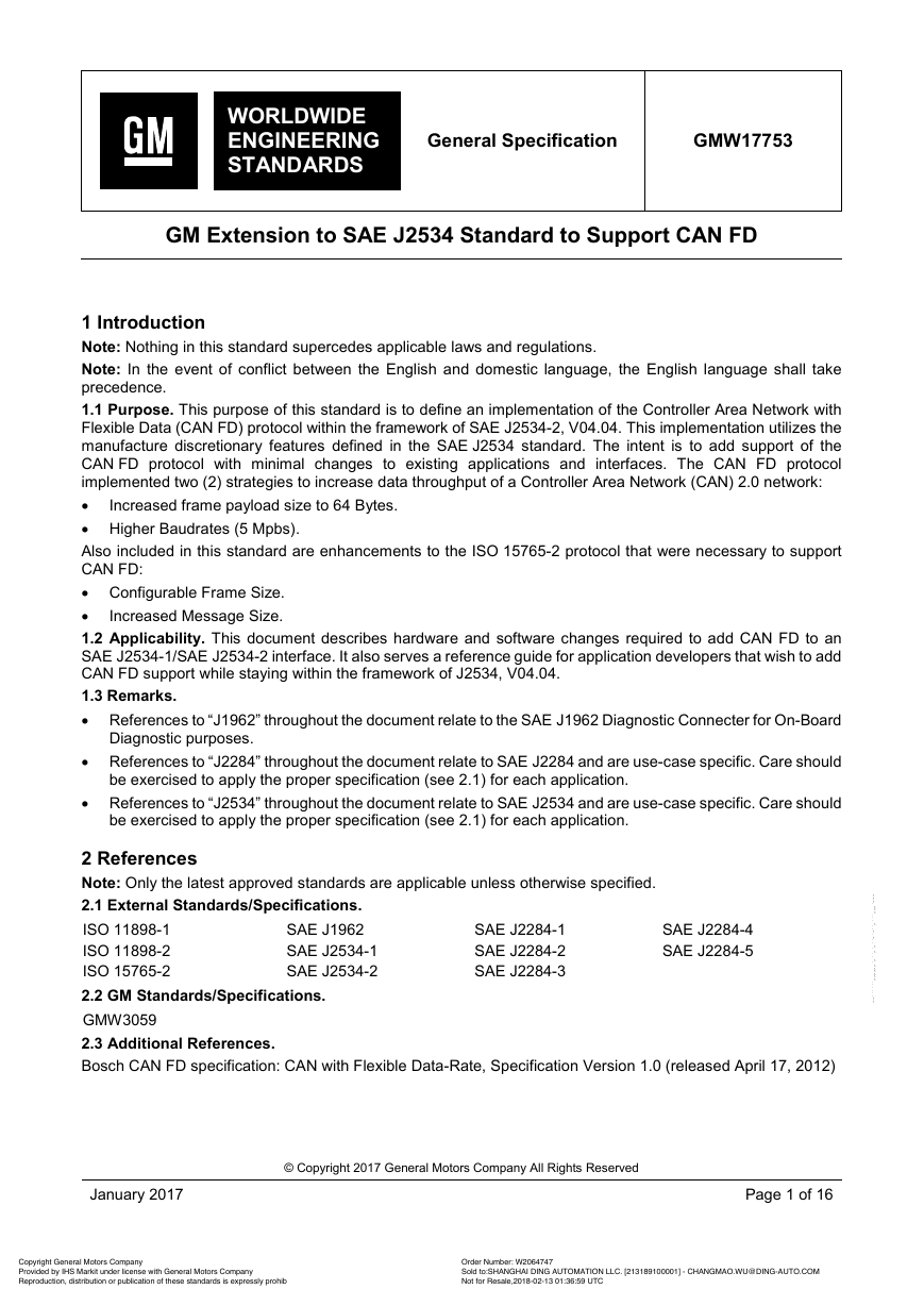
1 Introduction
1.1 Purpose. This purpose of this standard is to define an implementation of the Controller Area Network with Flexible Data (CAN FD) protocol within the framework of SAE J2534-2, V04.04. This implementation utilizes the manufacture discretionary featu...
1.2 Applicability. This document describes hardware and software changes required to add CAN FD to an SAE J2534-1/SAE J2534-2 interface. It also serves a reference guide for application developers that wish to add CAN FD support while staying within t...
1.3 Remarks.
2 References
2.1 External Standards/Specifications.
2.2 GM Standards/Specifications.
2.3 Additional References.
3 Requirements
3.1 Hardware Requirements.
3.1.1 CAN FD Channels. The Pass-Thru Interface shall have the ability of supporting at least two (2) concurrent ISO 11898-1/ISO 11898-2 CAN FD channels.
3.1.2 J1962 Pin Usage. See Table 1.
3.1.3 Termination Resistor. The Pass-Thru Interface have the capability of connecting a 120 Ω termination resistor across the J1962 pins of each channel. The state of the termination resistor shall be controlled by the application.
3.2 Protocol Identification (ProtocolID) Values. In order to identify Pass-Thru Device(s) that support CAN FD protocol, the device manufacture shall include the following Protocol Registry key in the J2534_V0404 registry hive. The value of the KEY sha...
3.3 Message Structure. The following defines how the J2534 Pass-Thru message type definition (typedef) structure (struct) elements that are used by the CAN_FD_PS and ISO15765_FD_PS protocol:
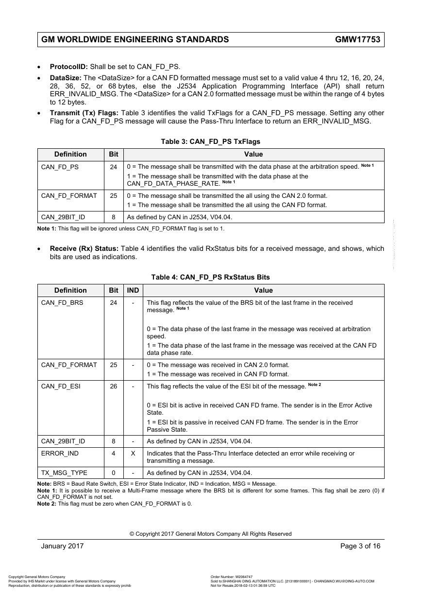
3.3.1 CAN_FD_PS Message Structure. The message structure parameters used for a CAN_FD_PS channel are very similar to CAN_PS (SAE J2534-2, V04.04). The following describes valid settings for each parameter; using any other settings will cause the Pass-...
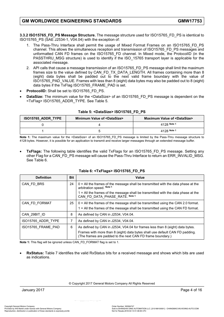
3.3.2 ISO15765_FD_PS Message Structure. The message structure used for ISO15765_FD_PS is identical to ISO15765_PS (SAE J2534-1, V04.04) with the exception of:
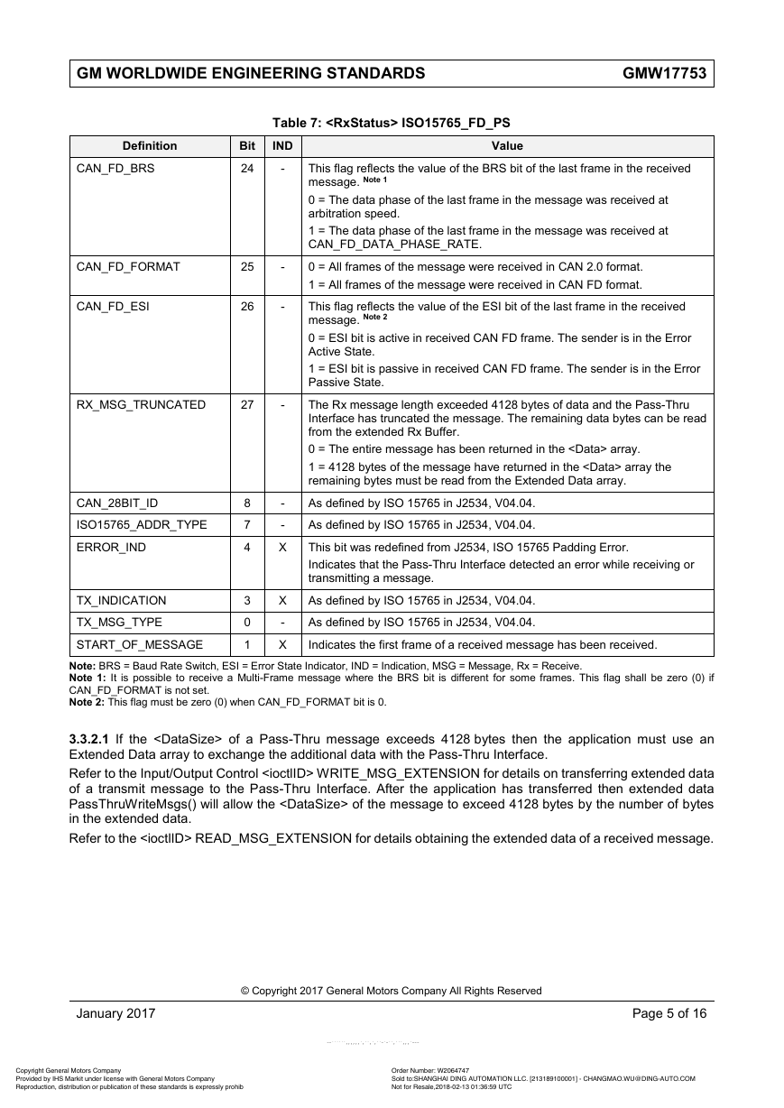
3.3.2.1 If the of a Pass-Thru message exceeds 4128 bytes then the application must use an Extended Data array to exchange the additional data with the Pass-Thru Interface.
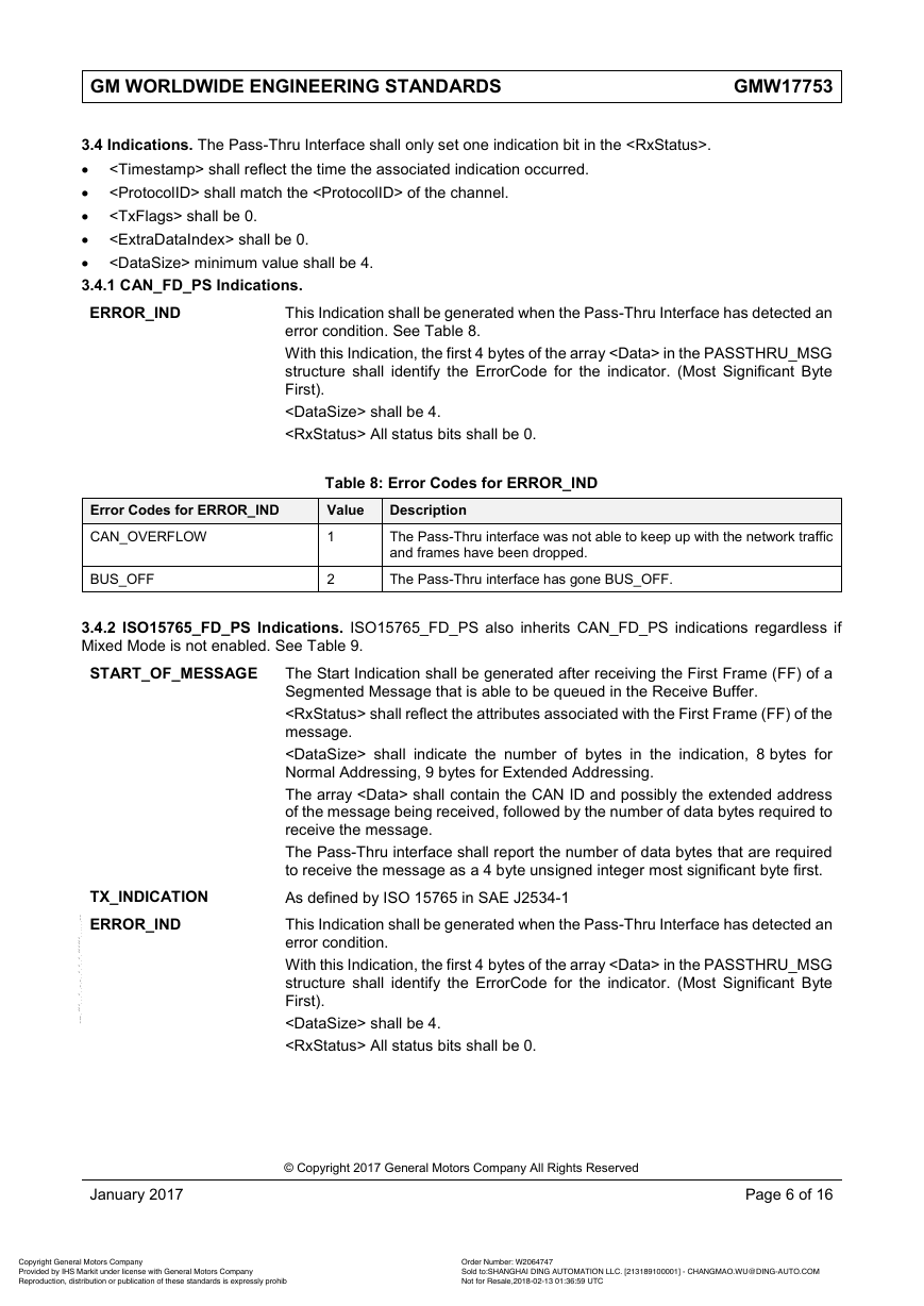
3.4 Indications. The Pass-Thru Interface shall only set one indication bit in the .
3.4.1 CAN_FD_PS Indications.
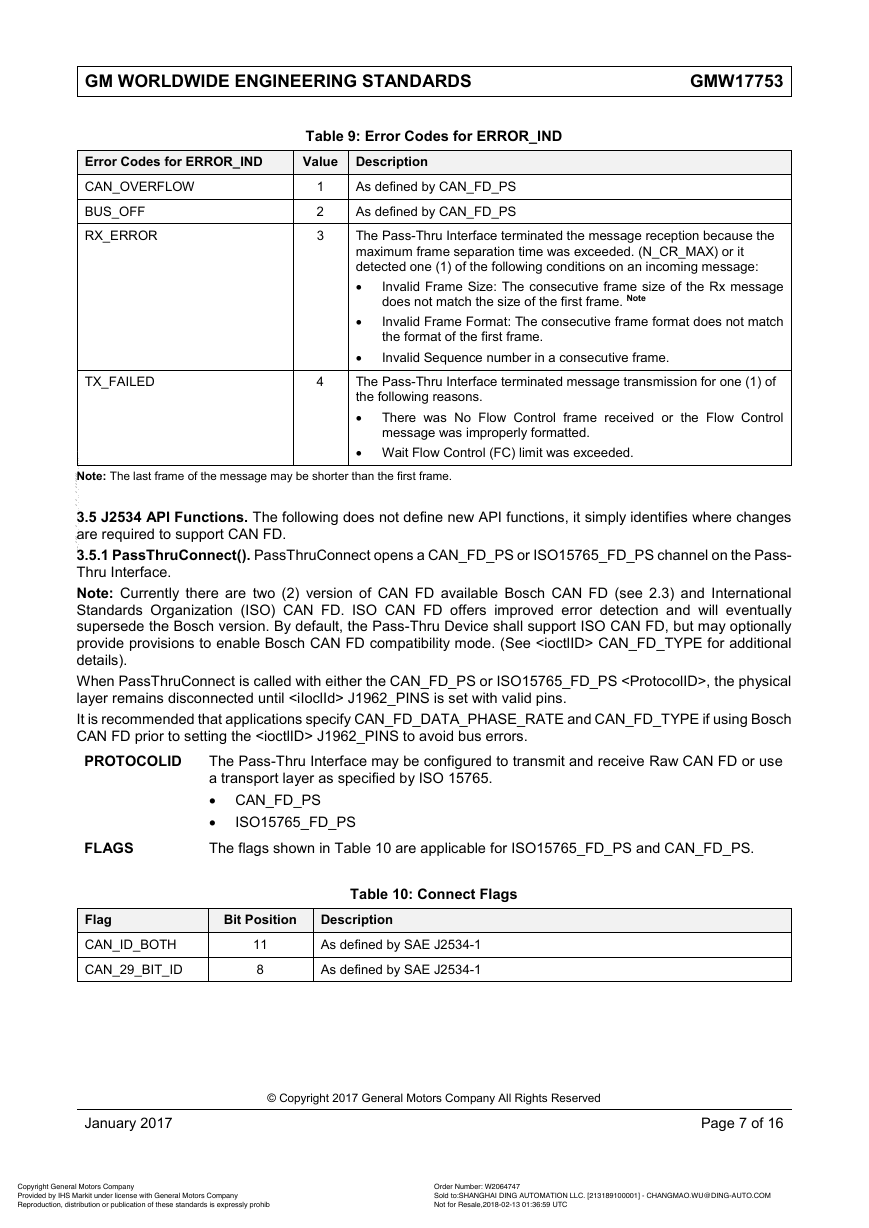
3.4.2 ISO15765_FD_PS Indications. ISO15765_FD_PS also inherits CAN_FD_PS indications regardless if Mixed Mode is not enabled. See Table 9.
3.5 J2534 API Functions. The following does not define new API functions, it simply identifies where changes are required to support CAN FD.
3.5.1 PassThruConnect(). PassThruConnect opens a CAN_FD_PS or ISO15765_FD_PS channel on the Pass-Thru Interface.
3.5.1.1 Return Values. As defined by SAE J2534-1.
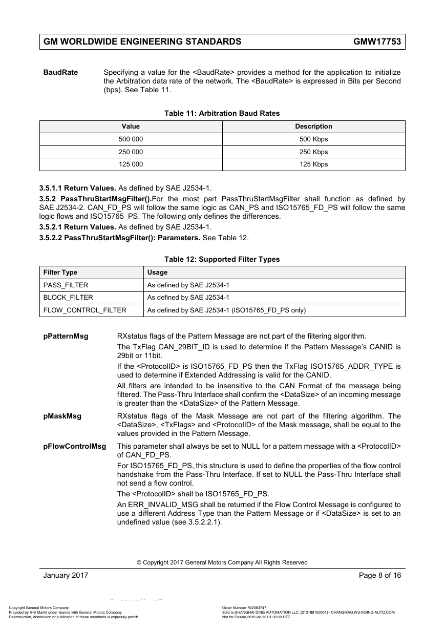
3.5.2 PassThruStartMsgFilter().For the most part PassThruStartMsgFilter shall function as defined by SAE J2534-2. CAN_FD_PS will follow the same logic as CAN_PS and ISO15765_FD_PS will follow the same logic flows and ISO15765_PS. The following only de...
3.5.2.1 Return Values. As defined by SAE J2534-1.
3.5.2.2 PassThruStartMsgFilter(): Parameters. See Table 12.
3.5.2.2.1 Dynamic Flow Control. Application that sends all node requests would normally be required to create a Flow Control Filter for each node capable of replying. A Dynamic Flow Control filter reduces the number of FLOW_CONTROL_FILTERS that are re...
3.5.2.3 Return Values. As defined by SAE J2534-1, however; the condition checks for the ERR_INVALID_MSG have been modified to account for dynamic Filter .
3.5.3 PassThruStartPeriodicMsg().For the most part PassThruStartPeriodicMsg remains as defined by SAE J2534-1. CAN_FD_PS inherits functionality from CAN, and ISO15765_FD_PS inherits functionality from ISO15765_PS. An ERR_INVALID_MSG shall be returned ...
3.5.3.1 Return Values. As defined by SAE J2534-1.
3.5.4 PassThruWriteMsg().For the most part CAN_FD_PS and ISO15765_FD_PS inherit all the basic functionality as defined by CAN_PS and ISO15765_PS respectively.
3.5.4.1 ISO 15765 Multi-Frame Messages. For multi-frame ISO15765_FD_PS messages, the Pass-Thru Interface must have a filter configured to receive the Flow Control response from the receiving node. If multiple messages have been queued for transmit, th...
3.5.4.2 Extended Tx Messages. PassThruWriteMsgs only allows the first message in the message list to have an extended message buffer. If any of the following conditions exist, PassThruWriteMsgs shall return value ERR_INVALID_MSG and the message will n...
3.5.4.3 Return Values. As defined by J2534 with the addition of the following tests.
3.5.5 PassThruReadMsgs().As defined by J2534, V04.04 except that support for messages beyond 4128 bytes is supported for ISO15765_FD_PS.
3.5.5.1 Extended Rx Messages. The Pass-Thru Interface shall set the RX_MSG_TRUNCATED status bit if of the received message exceeds 4128 bytes. The shall reflect the length of the received message even though the data field can on...
3.5.5.2 Return Values. As defined by SAE J2534-1.
3.5.6 PassThruIOCTL().The following SAE J2534-1 ioctlIDs are valid for CAN_FD_PS and ISO15765_FD_PS. See Table 19.
3.5.6.1 WRITE_MSG_EXTENSION. The WRITE_MSG_EXTENSION provides a method for an application to transmit a message that exceeds the PASS_THRU_MSG limit of 4128 data bytes. WRITE_MSG_EXTENSION is not supported by a CAN_FD_PS...
3.5.6.1.1 Return Values. For the most part the return values are defined as J2534 however; ERR_NOT_SUPPORTED has been modified to include the following conditions:
3.5.6.2 READ_MSG_EXTENSION. The Pass-Thru Interface shall store any data that was truncated by PassThruReadMsgs in a temporary buffer. The READ_MSG_EXTENSION provides a method for an application to read the data bytes of a message t...
3.5.6.2.1 Return Values. The return value of ERR_NOT_SUPPORTED shall be used to identify the following conditions:
3.5.6.3 CLEAR_TX_QUEUE. As defined by SAE J2534-1. However, also includes clearing the Extended Tx Data array if present.
3.5.6.4 CLEAR_RX_QUEUE. As defined by SAE J2534-1. However, also includes clearing the Extended Rx Data arrays if present.
3.5.6.5 SET_CONFIG and GET_CONFIG. See Table 22 and Table 24.
4 Validation
5 Provisions for Shipping
6 Notes
6.1 Glossary.
6.2 Acronyms, Abbreviations, and Symbols.
7 Additional Paragraphs
7.1 All parts or systems supplied to this standard must comply with the requirements of GMW3059, Restricted and Reportable Substances.
8 Coding System
9 Release and Revisions



 2023年江西萍乡中考道德与法治真题及答案.doc
 2012年重庆南川中考生物真题及答案.doc
 2013年江西师范大学地理学综合及文艺理论基础考研真题.doc
 2020年四川甘孜小升初语文真题及答案I卷.doc
 2020年注册岩土工程师专业基础考试真题及答案.doc
 2023-2024学年福建省厦门市九年级上学期数学月考试题及答案.doc
 2021-2022学年辽宁省沈阳市大东区九年级上学期语文期末试题及答案.doc
 2022-2023学年北京东城区初三第一学期物理期末试卷及答案.doc
 2018上半年江西教师资格初中地理学科知识与教学能力真题及答案.doc
 2012年河北国家公务员申论考试真题及答案-省级.doc
 2020-2021学年江苏省扬州市江都区邵樊片九年级上学期数学第一次质量检测试题及答案.doc
 2022下半年黑龙江教师资格证中学综合素质真题及答案.doc