PART 11: WIRELESS LAN MAC AND PHY SPECIFICATIONS
IEEE
Std 802.11-2007
17. Orthogonal frequency division multiplexing (OFDM) PHY specification
for the 5 GHz band
17.1 Introduction
This clause specifies the PHY entity for an orthogonal frequency division multiplexing (OFDM) system.
The OFDM system provides a WLAN with data payload communication capabilities of 6, 9, 12, 18, 24, 36,
48, and 54 Mb/s. The support of transmitting and receiving at data rates of 6, 12, and 24 Mb/s is mandatory.
The system uses 52 subcarriers that are modulated using binary or quadrature phase shift keying (BPSK or
QPSK) or using 16- or 64-quadrature amplitude modulation (16-QAM or 64-QAM). Forward error
correction coding (convolutional coding) is used with a coding rate of 1/2, 2/3, or 3/4.
The OFDM system also provides a “half-clocked” operation using 10 MHz channel spacings with data
communications capabilities of 3, 4.5, 6, 9, 12, 18, 24, and 27 Mb/s. The support of transmitting and
receiving at data rates of 3, 6, and 12 Mb/s is mandatory when using 10 MHz channel spacing. The half-
clocked operation doubles symbol times and clear channel assessment (CCA) times when using 10 MHz
channel spacing. The regulatory requirements and information regarding use of this OFDM system in
4.9 GHz and 5 GHz bands is in Annex I and Annex J.
The OFDM system also provides a “quarter-clocked” operation using 5 MHz channel spacing with data
communication capabilities of 1.5, 2.25, 3, 4.5, 6, 9, 12, and 13.5 Mb/s. The support of transmitting and
receiving at data rates of 1.5, 3, and 6 Mb/s is mandatory when using 5 MHz channel spacing. The quarter-
clocked operation quadruples symbol times and CCA times when using 5 MHz channel spacing. The
regulatory requirements and information regarding use of this OFDM system in the 4.9 GHz band is in
Annex I and Annex J.
17.1.1 Scope
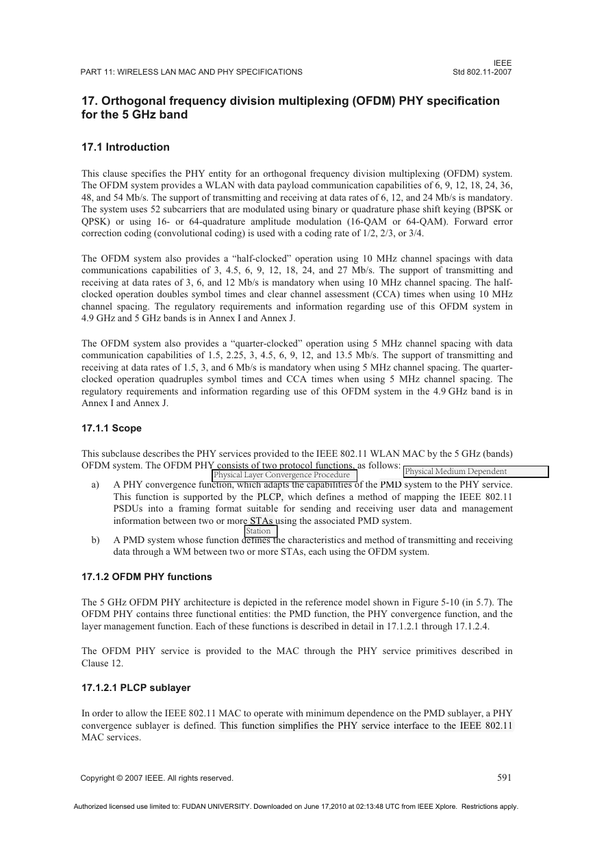
This subclause describes the PHY services provided to the IEEE 802.11 WLAN MAC by the 5 GHz (bands)
OFDM system. The OFDM PHY consists of two protocol functions, as follows:
PMD
Physical Medium Dependent
a) A PHY convergence function, which adapts the capabilities of the PMD system to the PHY service.
This function is supported by the PLCP, which defines a method of mapping the IEEE 802.11
PSDUs into a framing format suitable for sending and receiving user data and management
information between two or more STAs using the associated PMD system.
Physical Layer Convergence Procedure
p
PLCP,
STAs
Station
b) A PMD system whose function defines the characteristics and method of transmitting and receiving
data through a WM between two or more STAs, each using the OFDM system.
17.1.2 OFDM PHY functions
The 5 GHz OFDM PHY architecture is depicted in the reference model shown in Figure 5-10 (in 5.7). The
OFDM PHY contains three functional entities: the PMD function, the PHY convergence function, and the
layer management function. Each of these functions is described in detail in 17.1.2.1 through 17.1.2.4.
The OFDM PHY service is provided to the MAC through the PHY service primitives described in
Clause 12.
17.1.2.1 PLCP sublayer
In order to allow the IEEE 802.11 MAC to operate with minimum dependence on the PMD sublayer, a PHY
convergence sublayer is defined. This function simplifies the PHY service interface to the IEEE 802.11
This function simplifies the PHY service interface to the IEEE 802.11
MAC services.
p
p
y
Copyright © 2007 IEEE. All rights reserved.
591
Authorized licensed use limited to: FUDAN UNIVERSITY. Downloaded on June 17,2010 at 02:13:48 UTC from IEEE Xplore. Restrictions apply.
�
IEEE
Std 802.11-2007
17.1.2.2 PMD sublayer
LOCAL AND METROPOLITAN AREA NETWORKS—SPECIFIC REQUIREMENTS
The PMD sublayer provides a means to send and receive data between two or more STAs. This clause is
The PMD sublayer provides a means to send and receive data between two or more STAs.
concerned with the 5 GHz band using OFDM modulation.
17.1.2.3 PLME
The PLME performs management of the local PHY functions in conjunction with the MLME.
17.1.2.4 Service specification method
The models represented by figures and state diagrams are intended to be illustrations of the functions
provided. It is important to distinguish between a model and a real implementation. The models are
optimized for simplicity and clarity of presentation; the actual method of implementation is left to the
discretion of the IEEE 802.11 OFDM-PHY-compliant developer.
The service of a layer or sublayer is the set of capabilities that it offers to a user in the next higher layer (or
sublayer). Abstract services are specified here by describing the service primitives and parameters that
characterize each service. This definition is independent of any particular implementation.
17.2 OFDM PHY specific service parameter list
17.2.1 Introduction
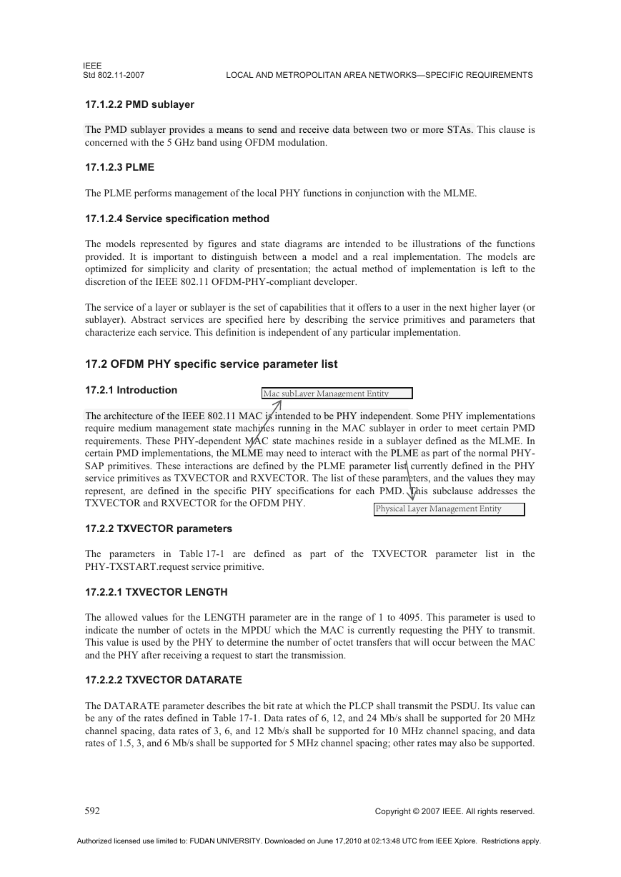
Mac subLayer Management Entity
The architecture of the IEEE 802.11 MAC is intended to be PHY independent. Some PHY implementations
The architecture of the IEEE 802.11 MAC is intended to be PHY independent
require medium management state machines running in the MAC sublayer in order to meet certain PMD
requirements. These PHY-dependent MAC state machines reside in a sublayer defined as the MLME. In
certain PMD implementations, the MLME may need to interact with the PLME as part of the normal PHY-
SAP primitives. These interactions are defined by the PLME parameter list currently defined in the PHY
service primitives as TXVECTOR and RXVECTOR. The list of these parameters, and the values they may
represent, are defined in the specific PHY specifications for each PMD. This subclause addresses the
TXVECTOR and RXVECTOR for the OFDM PHY.
y
PLME
MLME
Physical Layer Management Entity
17.2.2 TXVECTOR parameters
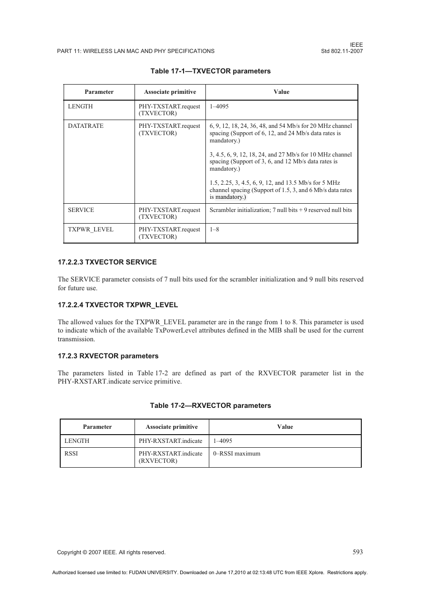
The parameters in Table 17-1 are defined as part of the TXVECTOR parameter list in the
PHY-TXSTART.request service primitive.
17.2.2.1 TXVECTOR LENGTH
The allowed values for the LENGTH parameter are in the range of 1 to 4095. This parameter is used to
indicate the number of octets in the MPDU which the MAC is currently requesting the PHY to transmit.
This value is used by the PHY to determine the number of octet transfers that will occur between the MAC
and the PHY after receiving a request to start the transmission.
17.2.2.2 TXVECTOR DATARATE
The DATARATE parameter describes the bit rate at which the PLCP shall transmit the PSDU. Its value can
be any of the rates defined in Table 17-1. Data rates of 6, 12, and 24 Mb/s shall be supported for 20 MHz
channel spacing, data rates of 3, 6, and 12 Mb/s shall be supported for 10 MHz channel spacing, and data
rates of 1.5, 3, and 6 Mb/s shall be supported for 5 MHz channel spacing; other rates may also be supported.
592
Copyright © 2007 IEEE. All rights reserved.
Authorized licensed use limited to: FUDAN UNIVERSITY. Downloaded on June 17,2010 at 02:13:48 UTC from IEEE Xplore. Restrictions apply.
�
PART 11: WIRELESS LAN MAC AND PHY SPECIFICATIONS
IEEE
Std 802.11-2007
Table 17-1—TXVECTOR parameters
Parameter
Associate primitive
Value
LENGTH
DATATRATE
PHY-TXSTART.request
(TXVECTOR)
1–4095
PHY-TXSTART.request
(TXVECTOR)
6, 9, 12, 18, 24, 36, 48, and 54 Mb/s for 20 MHz channel
spacing (Support of 6, 12, and 24 Mb/s data rates is
mandatory.)
3, 4.5, 6, 9, 12, 18, 24, and 27 Mb/s for 10 MHz channel
spacing (Support of 3, 6, and 12 Mb/s data rates is
mandatory.)
1.5, 2.25, 3, 4.5, 6, 9, 12, and 13.5 Mb/s for 5 MHz
channel spacing (Support of 1.5, 3, and 6 Mb/s data rates
is mandatory.)
mandatory.)
p
Scrambler initialization; 7 null bits + 9 reserved null bits
PHY-TXSTART.request
(TXVECTOR)
PHY-TXSTART.request
(TXVECTOR)
1–8
SERVICE
TXPWR_LEVEL
17.2.2.3 TXVECTOR SERVICE
The SERVICE parameter consists of 7 null bits used for the scrambler initialization and 9 null bits reserved
for future use.
17.2.2.4 TXVECTOR TXPWR_LEVEL
The allowed values for the TXPWR_LEVEL parameter are in the range from 1 to 8. This parameter is used
to indicate which of the available TxPowerLevel attributes defined in the MIB shall be used for the current
transmission.
17.2.3 RXVECTOR parameters
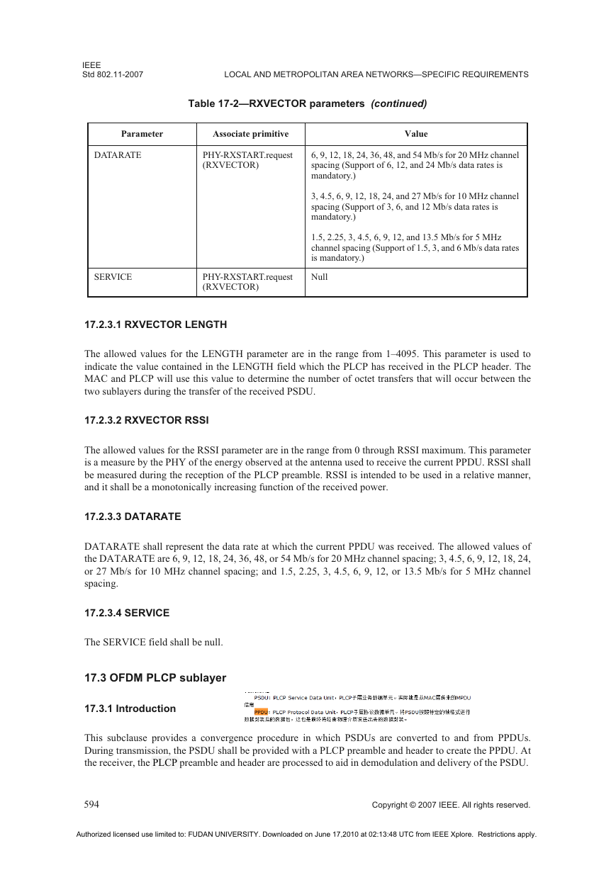
The parameters listed in Table 17-2 are defined as part of the RXVECTOR parameter list in the
PHY-RXSTART.indicate service primitive.
Table 17-2—RXVECTOR parameters
Parameter
Associate primitive
Value
LENGTH
RSSI
PHY-RXSTART.indicate
1–4095
PHY-RXSTART.indicate
(RXVECTOR)
0–RSSI maximum
Copyright © 2007 IEEE. All rights reserved.
593
Authorized licensed use limited to: FUDAN UNIVERSITY. Downloaded on June 17,2010 at 02:13:48 UTC from IEEE Xplore. Restrictions apply.
�
IEEE
Std 802.11-2007
LOCAL AND METROPOLITAN AREA NETWORKS—SPECIFIC REQUIREMENTS
Table 17-2—RXVECTOR parameters (continued)
Parameter
Associate primitive
Value
DATARATE
PHY-RXSTART.request
(RXVECTOR)
6, 9, 12, 18, 24, 36, 48, and 54 Mb/s for 20 MHz channel
spacing (Support of 6, 12, and 24 Mb/s data rates is
mandatory.)
3, 4.5, 6, 9, 12, 18, 24, and 27 Mb/s for 10 MHz channel
spacing (Support of 3, 6, and 12 Mb/s data rates is
mandatory.)
1.5, 2.25, 3, 4.5, 6, 9, 12, and 13.5 Mb/s for 5 MHz
channel spacing (Support of 1.5, 3, and 6 Mb/s data rates
is mandatory.)
SERVICE
PHY-RXSTART.request
(RXVECTOR)
Null
17.2.3.1 RXVECTOR LENGTH
The allowed values for the LENGTH parameter are in the range from 1–4095. This parameter is used to
indicate the value contained in the LENGTH field which the PLCP has received in the PLCP header. The
MAC and PLCP will use this value to determine the number of octet transfers that will occur between the
two sublayers during the transfer of the received PSDU.
17.2.3.2 RXVECTOR RSSI
The allowed values for the RSSI parameter are in the range from 0 through RSSI maximum. This parameter
is a measure by the PHY of the energy observed at the antenna used to receive the current PPDU. RSSI shall
be measured during the reception of the PLCP preamble. RSSI is intended to be used in a relative manner,
and it shall be a monotonically increasing function of the received power.
17.2.3.3 DATARATE
DATARATE shall represent the data rate at which the current PPDU was received. The allowed values of
the DATARATE are 6, 9, 12, 18, 24, 36, 48, or 54 Mb/s for 20 MHz channel spacing; 3, 4.5, 6, 9, 12, 18, 24,
or 27 Mb/s for 10 MHz channel spacing; and 1.5, 2.25, 3, 4.5, 6, 9, 12, or 13.5 Mb/s for 5 MHz channel
spacing.
17.2.3.4 SERVICE
The SERVICE field shall be null.
17.3 OFDM PLCP sublayer
17.3.1 Introduction
This subclause provides a convergence procedure in which PSDUs are converted to and from PPDUs.
During transmission, the PSDU shall be provided with a PLCP preamble and header to create the PPDU. At
the receiver, the PLCP preamble and header are processed to aid in demodulation and delivery of the PSDU.
PLCP p
594
Copyright © 2007 IEEE. All rights reserved.
Authorized licensed use limited to: FUDAN UNIVERSITY. Downloaded on June 17,2010 at 02:13:48 UTC from IEEE Xplore. Restrictions apply.
�
PART 11: WIRELESS LAN MAC AND PHY SPECIFICATIONS
17.3.2 PLCP frame format
IEEE
Std 802.11-2007
Figure 17-1 shows the format for the PPDU including the OFDM PLCP preamble, OFDM PLCP header,
PSDU, tail bits, and pad bits. The PLCP header contains the following fields: LENGTH, RATE, a reserved
bit, an even parity bit, and the SERVICE field. In terms of modulation, the LENGTH, RATE, reserved bit,
and parity bit (with 6 zero tail bits appended) constitute a separate single OFDM symbol, denoted SIGNAL,
which is transmitted with the most robust combination of BPSK modulation and a coding rate of R = 1/2.
The SERVICE field of the PLCP header and the PSDU (with 6 zero tail bits and pad bits appended), denoted
as DATA, are transmitted at the data rate described in the RATE field and may constitute multiple OFDM
symbols. The tail bits in the SIGNAL symbol enable decoding of the RATE and LENGTH fields
immediately after the reception of the tail bits. The RATE and LENGTH fields are required for decoding the
DATA part of the packet. In addition, the CCA mechanism can be augmented by predicting the duration of
the packet from the contents of the RATE and LENGTH fields, even if the data rate is not supported by the
STA. Each of these fields is described in detail in 17.3.3, 17.3.4, and 17.3.5.
PLCP Header
RATE
4 bits
Reserved
1 bit
LENGTH
12 bits
Parity
1 bit
Tail
6 bits
SERVICE
16 bits
PSDU
PSDU
Tail Pad Bits
6 bits
Coded/OFDM
(BPSK, r = 1/2)
Coded/OFDM
(RATE is indicated in SIGNAL)
PLCP Preamble
PLCP Preamble
PLCP Preamb
12 Symbols
12 Symbols
SIGNAL
One OFDM Symbol
DATA
Variable Number of OFDM Symbols
Figure 17-1—PPDU frame format
—PPDU
17.3.2.1 Overview of the PPDU encoding process
The encoding process is composed of many detailed steps, which are described fully in later subclauses, as
noted below. The following overview intends to facilitate understanding the details of the convergence
procedure:
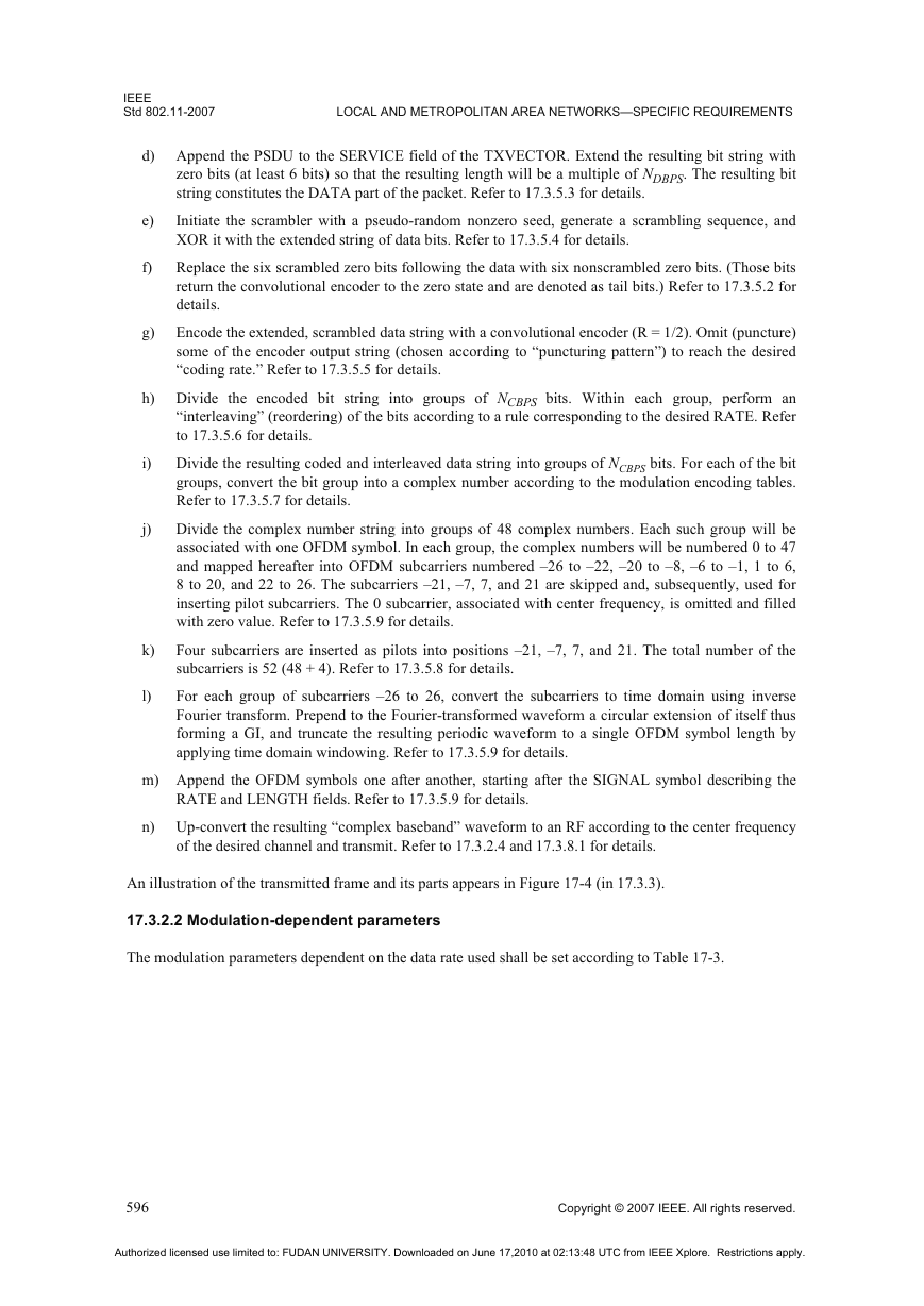
a)
b)
c)
Produce the PLCP Preamble field, composed of 10 repetitions of a “short training sequence” (used
for AGC convergence, diversity selection, timing acquisition, and coarse frequency acquisition in
the receiver) and two repetitions of a “long training sequence” (used for channel estimation and fine
frequency acquisition in the receiver), preceded by a guard interval (GI). Refer to 17.3.3 for details.
Produce the PLCP header field from the RATE, LENGTH, and SERVICE fields of the
TXVECTOR by filling the appropriate bit fields. The RATE and LENGTH fields of the PLCP
header are encoded by a convolutional code at a rate of R = 1/2, and are subsequently mapped onto a
single BPSK encoded OFDM symbol, denoted as the SIGNAL symbol. In order to facilitate a
reliable and timely detection of the RATE and LENGTH fields, 6 zero tail bits are inserted into the
PLCP header. The encoding of the SIGNAL field into an OFDM symbol follows the same steps for
convolutional encoding, interleaving, BPSK modulation, pilot insertion, Fourier transform, and
prepending a GI as described subsequently for data transmission with BPSK-OFDM modulated at
coding rate 1/2. The contents of the SIGNAL field are not scrambled. Refer to 17.3.4 for details.
Calculate from RATE field of the TXVECTOR the number of data bits per OFDM symbol (NDBPS),
the coding rate (R), the number of bits in each OFDM subcarrier (NBPSC), and the number of coded
bits per OFDM symbol (NCBPS). Refer to 17.3.2.2 for details.
Copyright © 2007 IEEE. All rights reserved.
595
Authorized licensed use limited to: FUDAN UNIVERSITY. Downloaded on June 17,2010 at 02:13:48 UTC from IEEE Xplore. Restrictions apply.
�
IEEE
Std 802.11-2007
LOCAL AND METROPOLITAN AREA NETWORKS—SPECIFIC REQUIREMENTS
e)
d) Append the PSDU to the SERVICE field of the TXVECTOR. Extend the resulting bit string with
zero bits (at least 6 bits) so that the resulting length will be a multiple of NDBPS. The resulting bit
string constitutes the DATA part of the packet. Refer to 17.3.5.3 for details.
Initiate the scrambler with a pseudo-random nonzero seed, generate a scrambling sequence, and
XOR it with the extended string of data bits. Refer to 17.3.5.4 for details.
Replace the six scrambled zero bits following the data with six nonscrambled zero bits. (Those bits
return the convolutional encoder to the zero state and are denoted as tail bits.) Refer to 17.3.5.2 for
details.
Encode the extended, scrambled data string with a convolutional encoder (R = 1/2). Omit (puncture)
some of the encoder output string (chosen according to “puncturing pattern”) to reach the desired
“coding rate.” Refer to 17.3.5.5 for details.
g)
f)
i)
j)
h) Divide the encoded bit string into groups of NCBPS bits. Within each group, perform an
“interleaving” (reordering) of the bits according to a rule corresponding to the desired RATE. Refer
to 17.3.5.6 for details.
Divide the resulting coded and interleaved data string into groups of NCBPS bits. For each of the bit
groups, convert the bit group into a complex number according to the modulation encoding tables.
Refer to 17.3.5.7 for details.
Divide the complex number string into groups of 48 complex numbers. Each such group will be
associated with one OFDM symbol. In each group, the complex numbers will be numbered 0 to 47
and mapped hereafter into OFDM subcarriers numbered –26 to –22, –20 to –8, –6 to –1, 1 to 6,
8 to 20, and 22 to 26. The subcarriers –21, –7, 7, and 21 are skipped and, subsequently, used for
inserting pilot subcarriers. The 0 subcarrier, associated with center frequency, is omitted and filled
with zero value. Refer to 17.3.5.9 for details.
Four subcarriers are inserted as pilots into positions –21, –7, 7, and 21. The total number of the
subcarriers is 52 (48 + 4). Refer to 17.3.5.8 for details.
For each group of subcarriers –26 to 26, convert the subcarriers to time domain using inverse
Fourier transform. Prepend to the Fourier-transformed waveform a circular extension of itself thus
forming a GI, and truncate the resulting periodic waveform to a single OFDM symbol length by
applying time domain windowing. Refer to 17.3.5.9 for details.
k)
l)
m) Append the OFDM symbols one after another, starting after the SIGNAL symbol describing the
RATE and LENGTH fields. Refer to 17.3.5.9 for details.
n) Up-convert the resulting “complex baseband” waveform to an RF according to the center frequency
of the desired channel and transmit. Refer to 17.3.2.4 and 17.3.8.1 for details.
An illustration of the transmitted frame and its parts appears in Figure 17-4 (in 17.3.3).
17.3.2.2 Modulation-dependent parameters
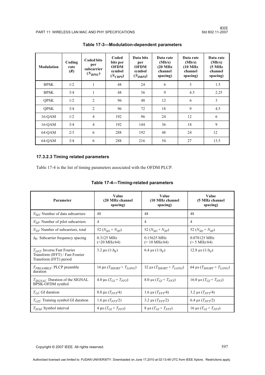
The modulation parameters dependent on the data rate used shall be set according to Table 17-3.
596
Copyright © 2007 IEEE. All rights reserved.
Authorized licensed use limited to: FUDAN UNIVERSITY. Downloaded on June 17,2010 at 02:13:48 UTC from IEEE Xplore. Restrictions apply.
�
PART 11: WIRELESS LAN MAC AND PHY SPECIFICATIONS
IEEE
Std 802.11-2007
Table 17-3—Modulation-dependent parameters
Modulation
Coding
rate
(R)
Coded bits
per
subcarrier
(NBPSC)
Coded
bits per
OFDM
symbol
(NCBPS)
Data bits
per
OFDM
symbol
(NDBPS)
Data rate
(Mb/s)
(20 MHz
channel
spacing)
Data rate
(Mb/s)
(10 MHz
channel
spacing)
Data rate
(Mb/s)
(5 MHz
channel
spacing)
BPSK
BPSK
QPSK
QPSK
16-QAM
16-QAM
64-QAM
64-QAM
1/2
3/4
1/2
3/4
1/2
3/4
2/3
3/4
1
1
2
2
4
4
6
6
48
48
96
96
192
192
288
288
24
36
48
72
96
144
192
216
6
9
12
18
24
36
48
54
3
4.5
6
9
12
18
24
27
1.5
2.25
3
4.5
6
9
12
13.5
17.3.2.3 Timing related parameters
Table 17-4 is the list of timing parameters associated with the OFDM PLCP.
Table 17-4—Timing-related parameters
Parameter
NSD: Number of data subcarriers
NSP: Number of pilot subcarriers
NST: Number of subcarriers, total
ΔF: Subcarrier frequency spacing
TFFT: Inverse Fast Fourier
Transform (IFFT) / Fast Fourier
Transform (FFT) period
TPREAMBLE: PLCP preamble
duration
TSIGNAL: Duration of the SIGNAL
BPSK-OFDM symbol
TGI: GI duration
TGI2: Training symbol GI duration
TSYM: Symbol interval
Value
(20 MHz channel
spacing)
Value
(10 MHz channel
spacing)
Value
(5 MHz channel
spacing)
48
4
52 (NSD + NSP)
0.3125 MHz
(=20 MHz/64)
3.2 μs (1/ΔF)
48
4
52 (NSD + NSP)
0.15625 MHz
(= 10 MHz/64)
6.4 μs (1/ΔF)
48
4
52 (NSD + NSP)
0.078125 MHz
(= 5 MHz/64)
12.8 μs (1/ΔF)
16 μs (TSHORT + TLONG)
32 μs (TSHORT + TLONG)
64 μs (TSHORT + TLONG)
4.0 μs (TGI + TFFT)
8.0 μs (TGI + TFFT)
16.0 μs (TGI + TFFT)
0.8 μs (TFFT/4)
1.6 μs (TFFT/2)
4 μs (TGI + TFFT)
1.6 μs (TFFT/4)
3.2 μs (TFFT/2)
8 μs (TGI + TFFT)
3.2 μs (TFFT/4)
6.4 μs (TFFT/2)
16 μs (TGI + TFFT)
Copyright © 2007 IEEE. All rights reserved.
597
Authorized licensed use limited to: FUDAN UNIVERSITY. Downloaded on June 17,2010 at 02:13:48 UTC from IEEE Xplore. Restrictions apply.
�
IEEE
Std 802.11-2007
LOCAL AND METROPOLITAN AREA NETWORKS—SPECIFIC REQUIREMENTS
Table 17-4—Timing-related parameters (continued)
Parameter
TSHORT: Short training sequence
duration
TLONG: Long training sequence
duration
Value
(20 MHz channel
spacing)
8 μs (10 × TFFT /4)
Value
(10 MHz channel
spacing)
Value
(5 MHz channel
spacing)
16 μs (10 × TFFT/4)
32 μs (10 × TFFT/4)
8 μs (TGI2 + 2 × TFFT)
16 μs (TGI2 + 2 × TFFT)
32 μs (TGI2 + 2 × TFFT)
17.3.2.4 Mathematical conventions in the signal descriptions
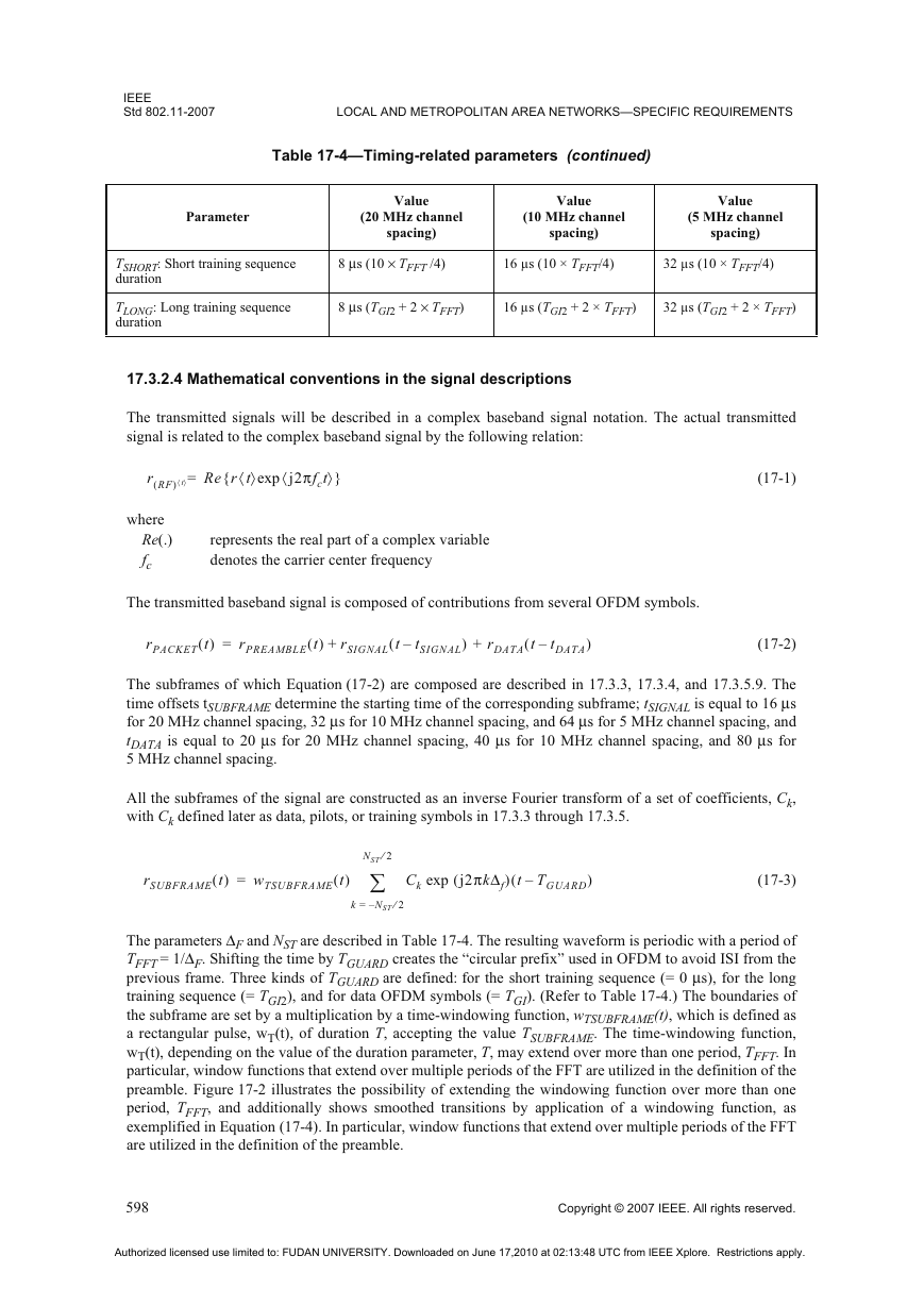
The transmitted signals will be described in a complex baseband signal notation. The actual transmitted
signal is related to the complex baseband signal by the following relation:
r RF(
) t¢ ² Re{r t¢ ²exp j2πfct
=
¢
²}
(17-1)
where
Re(.)
fc
represents the real part of a complex variable
denotes the carrier center frequency
The transmitted baseband signal is composed of contributions from several OFDM symbols.
rPACKET t( )
=
rPREAMBLE t( )
+
rSIGNAL t
–(
tSIGNAL
) + rDATA t
–(
tDATA
)
(17-2)
The subframes of which Equation (17-2) are composed are described in 17.3.3, 17.3.4, and 17.3.5.9. The
time offsets tSUBFRAME determine the starting time of the corresponding subframe; tSIGNAL is equal to 16 μs
for 20 MHz channel spacing, 32 μs for 10 MHz channel spacing, and 64 μs for 5 MHz channel spacing, and
tDATA is equal to 20 μs for 20 MHz channel spacing, 40 μs for 10 MHz channel spacing, and 80 μs for
5 MHz channel spacing.
All the subframes of the signal are constructed as an inverse Fourier transform of a set of coefficients, Ck,
with Ck defined later as data, pilots, or training symbols in 17.3.3 through 17.3.5.
rSUBFRAME t( )
=
wTSUBFRAME t( )
NST 2⁄
¦
N– ST 2⁄
=
k
Ck exp j2πkΔf
(
) t TGUARD
–(
)
(17-3)
The parameters ΔF and NST are described in Table 17-4. The resulting waveform is periodic with a period of
TFFT = 1/ΔF. Shifting the time by TGUARD creates the “circular prefix” used in OFDM to avoid ISI from the
previous frame. Three kinds of TGUARD are defined: for the short training sequence (= 0 μs), for the long
training sequence (= TGI2), and for data OFDM symbols (= TGI). (Refer to Table 17-4.) The boundaries of
the subframe are set by a multiplication by a time-windowing function, wTSUBFRAME(t), which is defined as
a rectangular pulse, wT(t), of duration T, accepting the value TSUBFRAME. The time-windowing function,
wT(t), depending on the value of the duration parameter, T, may extend over more than one period, TFFT. In
particular, window functions that extend over multiple periods of the FFT are utilized in the definition of the
preamble. Figure 17-2 illustrates the possibility of extending the windowing function over more than one
period, TFFT, and additionally shows smoothed transitions by application of a windowing function, as
exemplified in Equation (17-4). In particular, window functions that extend over multiple periods of the FFT
are utilized in the definition of the preamble.
598
Copyright © 2007 IEEE. All rights reserved.
Authorized licensed use limited to: FUDAN UNIVERSITY. Downloaded on June 17,2010 at 02:13:48 UTC from IEEE Xplore. Restrictions apply.
�



 2023年江西萍乡中考道德与法治真题及答案.doc
 2012年重庆南川中考生物真题及答案.doc
 2013年江西师范大学地理学综合及文艺理论基础考研真题.doc
 2020年四川甘孜小升初语文真题及答案I卷.doc
 2020年注册岩土工程师专业基础考试真题及答案.doc
 2023-2024学年福建省厦门市九年级上学期数学月考试题及答案.doc
 2021-2022学年辽宁省沈阳市大东区九年级上学期语文期末试题及答案.doc
 2022-2023学年北京东城区初三第一学期物理期末试卷及答案.doc
 2018上半年江西教师资格初中地理学科知识与教学能力真题及答案.doc
 2012年河北国家公务员申论考试真题及答案-省级.doc
 2020-2021学年江苏省扬州市江都区邵樊片九年级上学期数学第一次质量检测试题及答案.doc
 2022下半年黑龙江教师资格证中学综合素质真题及答案.doc