logo资料库

[络达(Airoha)] 络达AB1532的规格书手册DATASHEET.pdf

第1页 / 共76页
第2页 / 共76页
第3页 / 共76页
第4页 / 共76页
第5页 / 共76页
第6页 / 共76页
第7页 / 共76页
第8页 / 共76页
资料共76页,剩余部分请下载后查看
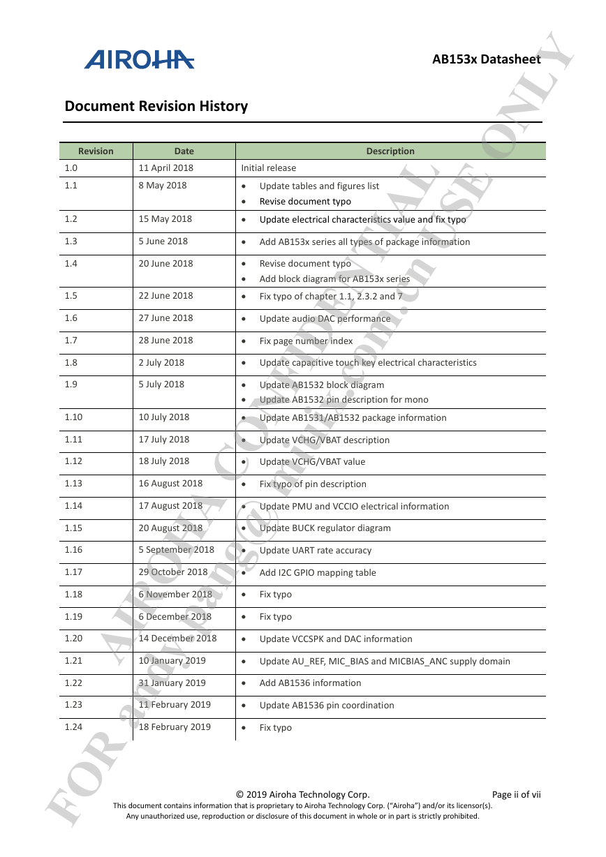
Document Revision History
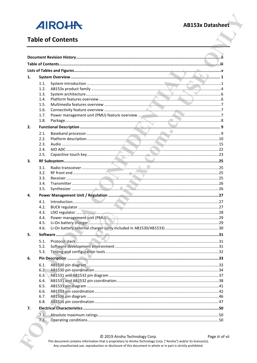
Table of Contents
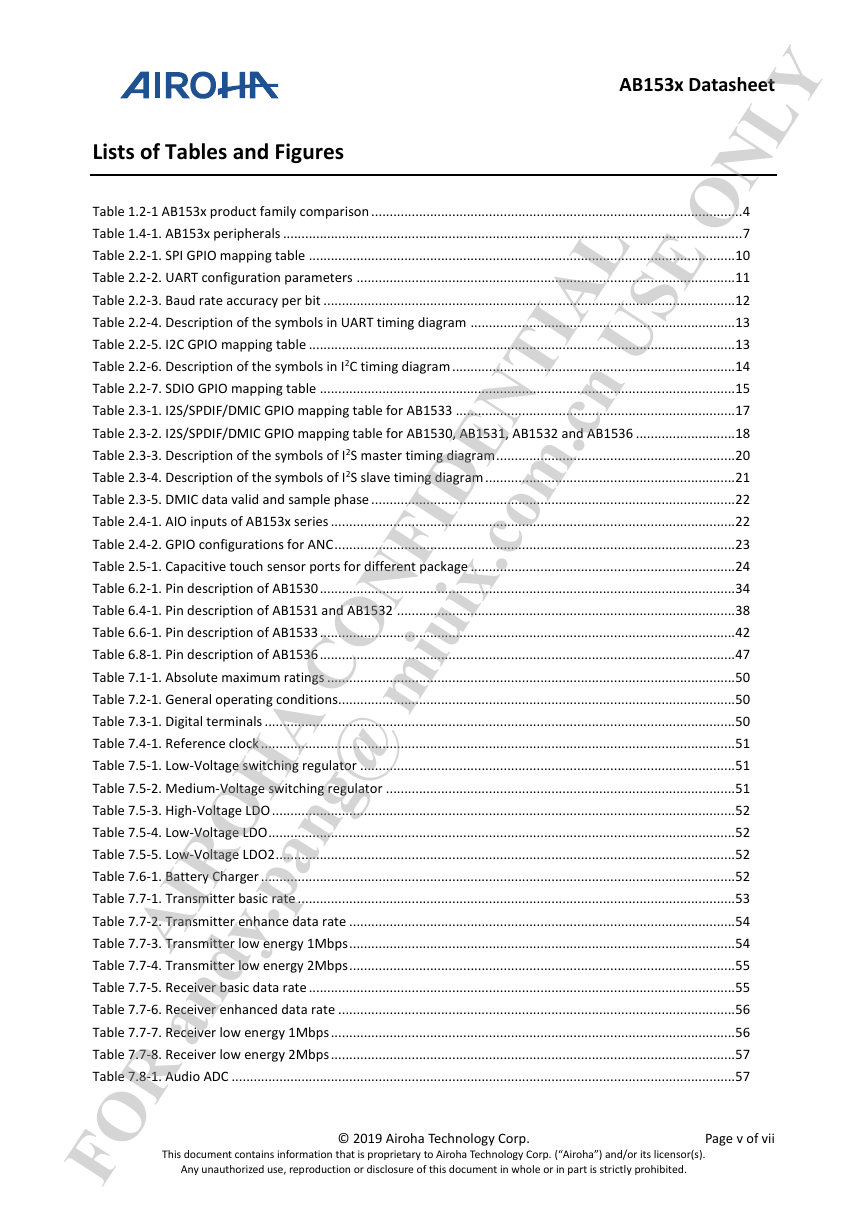
Lists of Tables and Figures
1. System Overview
1.1. System introduction
1.2. AB153x product family
1.3. System architecture
1.4. Platform features overview
1.4.1. Baseband processor system
1.4.2. Clock
1.4.3. Peripheral interfaces
1.5. Multimedia features overview
1.5.1. Audio interface
1.6. Connectivity feature overview
1.6.1. Bluetooth
1.7. Power management unit (PMU) feature overview
1.8. Package
2. Functional Description
2.1. Baseband processor
2.1.1. Bluetooth processing unit
2.1.2. Modem
2.2. Platform description
2.2.1. SPI
2.2.2. UART
2.2.3. I2C
2.2.4. USB
2.2.5. SDIO
2.2.6. PWM
2.3. Audio
2.3.1. Audio interface
2.3.2. Analog audio input
2.3.3. Analog audio output
2.3.4. Line input (only included in AB1530/AB1533)
2.3.5. Digital audio interface
2.3.6. I2S interface
2.3.7. SPDIF-IN/OUT interface
2.3.8. Digital microphone (DMIC) interface
2.4. AIO ADC
2.4.1. AIO ADC configuration
2.4.2. AIO ADC interface for ANC (only included in AB1533)
2.5. Capacitive touch key
3. RF Subsystem
3.1. Radio transceiver
3.2. RF front end
3.3. Receiver
3.4. Transmitter
3.5. Synthesizer
4. Power Management Unit / Regulation
4.1. Introduction
4.2. BUCK regulator
4.3. LDO regulator
4.4. Power management unit (PMU)
4.5. Li-On battery charger
4.6. Li-On battery external charger (only included in AB1530/AB1533)
5. Software
5.1. Protocol stack
5.2. Software development environment
5.3. Testing and configuration tools
6. Pin Description
6.1. AB1530 pin diagram
6.2. AB1530 pin coordination
6.3. AB1531 and AB1532 pin diagram
6.4. AB1531 and AB1532 pin coordination
6.5. AB1533 pin diagram
6.6. AB1533 pin coordination
6.7. AB1536 pin diagram
6.8. AB1536 pin coordination
7. Electrical Characteristics
7.1. Absolute maximum ratings
7.2. Operating conditions
7.3. Digital terminals
7.4. Reference clock
7.5. Power
7.5.1. Low-Voltage switching regulator
7.5.2. Medium-Voltage switching regulator
7.5.3. High-Voltage LDO
7.5.4. Low-Voltage LDO
7.5.5. Low-Voltage LDO2
7.6. Battery charger
7.7. Radio characteristic (25 C)
7.7.1. Transmitter
7.7.2. Receiver
7.8. Audio ADC
7.9. Stereo DAC
7.10. AIO ADC
7.11. Capacitive touch key
8. Package Information
8.1. AB1530 package information
8.2. AB1531 and AB1532 package information
8.3. AB1533 package information
8.4. AB1536 package information
9. Ordering Information
9.1. Ordering information
FOR andy.pang@ miuix.com.cn USE ONLY AIROHA CONFIDENTIAL This document contains information that is proprietary to Airoha Technology Corp. (“Airoha”) and/or its licensor(s). Airoha cannot grant you permission for any material that is owned by third parties. You may only use or reproduce this document if you have agreed to and been bound by the applicable license agreement with Airoha (“License Agreement”) and been granted explicit permission within the License Agreement (“Permitted User”). If you are not a Permitted User, please cease any access or use of this document immediately. Any unauthorized use, reproduction or disclosure of this document in whole or in part is strictly prohibited. THIS DOCUMENT IS PROVIDED ON AN “AS-IS” BASIS ONLY. AIROHA EXPRESSLY DISCLAIMS ANY AND ALL WARRANTIES OF ANY KIND AND SHALL IN NO EVENT BE LIABLE FOR ANY CLAIMS RELATING TO OR ARISING OUT OF THIS DOCUMENT OR ANY USE OR INABILITY TO USE THEREOF. Specifications contained herein are subject to change without notice. AB153x Datasheet 20 February 2019 Version: © 2019 Airoha Technology Corp. Release date: 1.24
8 May 2018 Description 15 May 2018 5 June 2018 20 June 2018 22 June 2018 27 June 2018 Revision Date 2 July 2018 5 July 2018 28 June 2018  Fix page number index 1.10 10 July 2018 11 April 2018 Initial release 1.0 1.1 1.2 1.3 1.4 1.5 1.6 1.7 1.8 1.9  Update audio DAC performance AB153x Datasheet  Fix typo of chapter 1.1, 2.3.2 and 7  Update electrical characteristics value and fix typo  Add AB153x series all types of package information  Update capacitive touch key electrical characteristics Document Revision History  Update tables and figures list  Revise document typo  Revise document typo  Add block diagram for AB153x series FOR andy.pang@ miuix.com.cn USE ONLY AIROHA CONFIDENTIAL  Update AB1532 block diagram  Update AB1532 pin description for mono This document contains information that is proprietary to Airoha Technology Corp. (“Airoha”) and/or its licensor(s). Any unauthorized use, reproduction or disclosure of this document in whole or in part is strictly prohibited.  Update AU_REF, MIC_BIAS and MICBIAS_ANC supply domain  Update PMU and VCCIO electrical information  Update AB1531/AB1532 package information  Update VCCSPK and DAC information  Update AB1536 pin coordination  Update BUCK regulator diagram  Update VCHG/VBAT description 1.11 1.12 1.13 1.14 1.15 1.16 1.17 1.18  Add I2C GPIO mapping table © 2019 Airoha Technology Corp.  Update UART rate accuracy 1.19 1.20 1.21 1.22 1.23 1.24 18 February 2019  Fix typo  Fix typo of pin description   Fix typo Fix typo 31 January 2019  Add AB1536 information 18 July 2018  Update VCHG/VBAT value 14 December 2018 5 September 2018 16 August 2018 17 August 2018 20 August 2018 11 February 2019 29 October 2018 6 November 2018 6 December 2018 17 July 2018 10 January 2019 Page ii of vii
AB153x Datasheet Table of Contents FOR andy.pang@ miuix.com.cn USE ONLY AIROHA CONFIDENTIAL Document Revision History ...............................................................................................................................ii Table of Contents ............................................................................................................................................. iii Lists of Tables and Figures ................................................................................................................................. v 1. System Overview ................................................................................................................................... 1 1.1. System introduction ........................................................................................................................... 1 1.2. AB153x product family ....................................................................................................................... 4 1.3. System architecture ............................................................................................................................ 6 1.4. Platform features overview ................................................................................................................ 6 1.5. Multimedia features overview ........................................................................................................... 7 1.6. Connectivity feature overview ........................................................................................................... 7 1.7. Power management unit (PMU) feature overview ............................................................................ 7 1.8. Package ............................................................................................................................................... 8 Functional Description ........................................................................................................................... 9 2.1. Baseband processor............................................................................................................................ 9 2.2. Platform description ......................................................................................................................... 10 2.3. Audio ................................................................................................................................................ 15 2.4. AIO ADC ............................................................................................................................................ 22 2.5. Capacitive touch key ......................................................................................................................... 23 RF Subsystem ........................................................................................................................................ 25 3.1. Radio transceiver .............................................................................................................................. 25 3.2. RF front end ...................................................................................................................................... 25 3.3. Receiver ............................................................................................................................................ 25 3.4. Transmitter ....................................................................................................................................... 26 3.5. Synthesizer ....................................................................................................................................... 26 Power Management Unit / Regulation ................................................................................................. 27 4.1. Introduction ...................................................................................................................................... 27 4.2. BUCK regulator ................................................................................................................................. 27 4.3. LDO regulator ................................................................................................................................... 28 4.4. Power management unit (PMU) ....................................................................................................... 29 Li-On battery charger ........................................................................................................................ 29 4.5. 4.6. Li-On battery external charger (only included in AB1530/AB1533) ................................................. 30 Software ............................................................................................................................................... 31 5.1. Protocol stack ................................................................................................................................... 31 5.2. Software development environment ............................................................................................... 31 5.3. Testing and configuration tools ........................................................................................................ 32 Pin Description ..................................................................................................................................... 33 6.1. AB1530 pin diagram ......................................................................................................................... 33 6.2. AB1530 pin coordination .................................................................................................................. 34 6.3. AB1531 and AB1532 pin diagram ..................................................................................................... 37 6.4. AB1531 and AB1532 pin coordination .............................................................................................. 38 6.5. AB1533 pin diagram ......................................................................................................................... 41 6.6. AB1533 pin coordination .................................................................................................................. 42 6.7. AB1536 pin diagram ......................................................................................................................... 46 6.8. AB1536 pin coordination .................................................................................................................. 47 Electrical Characteristics ....................................................................................................................... 50 7.1. Absolute maximum ratings ............................................................................................................... 50 7.2. Operating conditions ........................................................................................................................ 50 This document contains information that is proprietary to Airoha Technology Corp. (“Airoha”) and/or its licensor(s). Any unauthorized use, reproduction or disclosure of this document in whole or in part is strictly prohibited. © 2019 Airoha Technology Corp. Page iii of vii 2. 3. 4. 5. 6. 7.
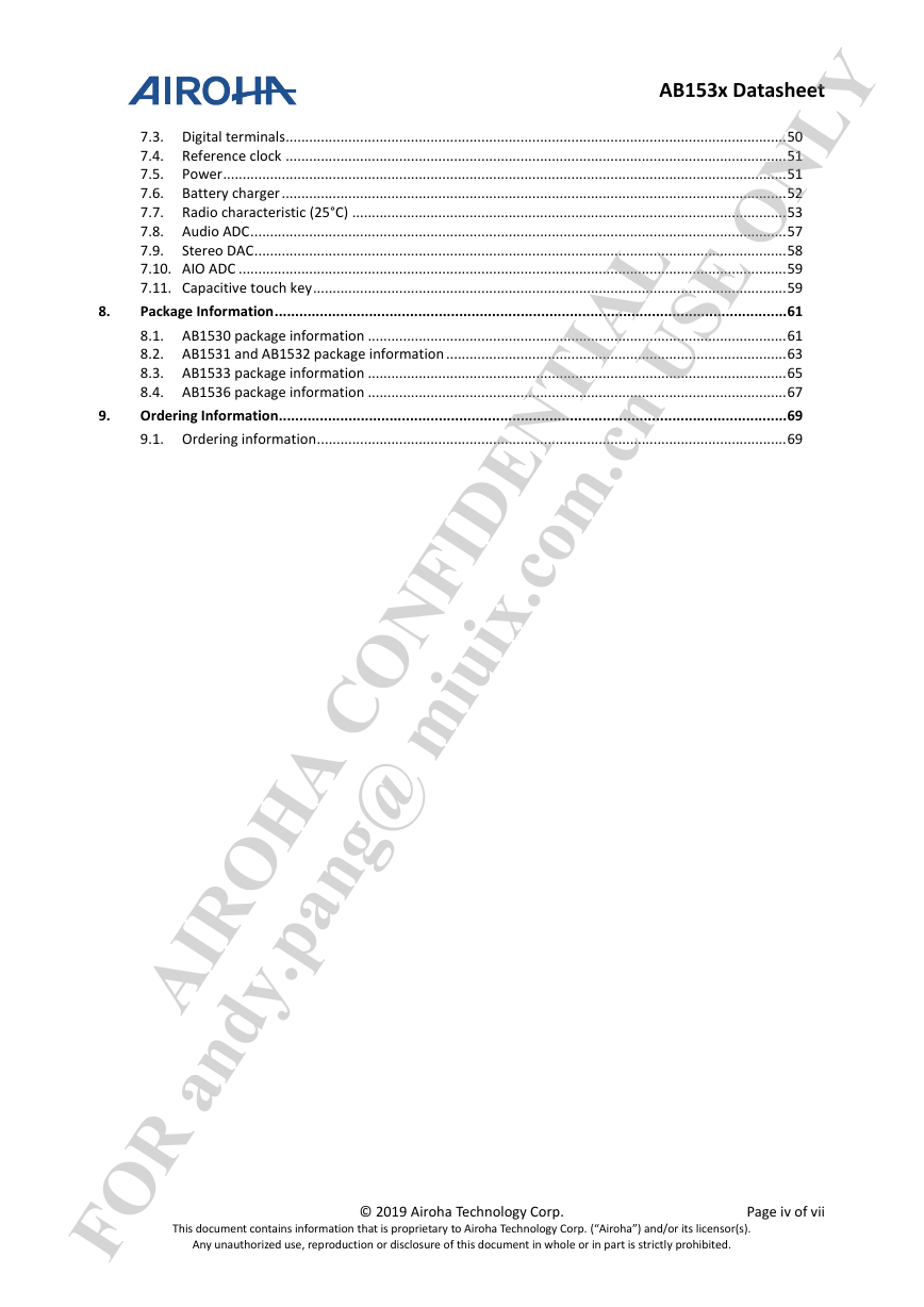
8. 9. AB153x Datasheet 7.3. Digital terminals ................................................................................................................................ 50 7.4. Reference clock ................................................................................................................................ 51 7.5. Power ................................................................................................................................................ 51 7.6. Battery charger ................................................................................................................................. 52 7.7. Radio characteristic (25°C) ............................................................................................................... 53 7.8. Audio ADC ......................................................................................................................................... 57 7.9. Stereo DAC ........................................................................................................................................ 58 7.10. AIO ADC ............................................................................................................................................ 59 7.11. Capacitive touch key ......................................................................................................................... 59 Package Information ............................................................................................................................. 61 8.1. AB1530 package information ........................................................................................................... 61 8.2. AB1531 and AB1532 package information ....................................................................................... 63 8.3. AB1533 package information ........................................................................................................... 65 8.4. AB1536 package information ........................................................................................................... 67 Ordering Information ............................................................................................................................ 69 9.1. Ordering information ........................................................................................................................ 69 FOR andy.pang@ miuix.com.cn USE ONLY AIROHA CONFIDENTIAL This document contains information that is proprietary to Airoha Technology Corp. (“Airoha”) and/or its licensor(s). Any unauthorized use, reproduction or disclosure of this document in whole or in part is strictly prohibited. © 2019 Airoha Technology Corp. Page iv of vii
AB153x Datasheet Lists of Tables and Figures FOR andy.pang@ miuix.com.cn USE ONLY AIROHA CONFIDENTIAL Table 1.2-1 AB153x product family comparison ..................................................................................................... 4 Table 1.4-1. AB153x peripherals ............................................................................................................................. 7 Table 2.2-1. SPI GPIO mapping table .................................................................................................................... 10 Table 2.2-2. UART configuration parameters ....................................................................................................... 11 Table 2.2-3. Baud rate accuracy per bit ................................................................................................................ 12 Table 2.2-4. Description of the symbols in UART timing diagram ........................................................................ 13 Table 2.2-5. I2C GPIO mapping table .................................................................................................................... 13 Table 2.2-6. Description of the symbols in I2C timing diagram ............................................................................. 14 Table 2.2-7. SDIO GPIO mapping table ................................................................................................................. 15 Table 2.3-1. I2S/SPDIF/DMIC GPIO mapping table for AB1533 ............................................................................ 17 Table 2.3-2. I2S/SPDIF/DMIC GPIO mapping table for AB1530, AB1531, AB1532 and AB1536 ........................... 18 Table 2.3-3. Description of the symbols of I2S master timing diagram ................................................................. 20 Table 2.3-4. Description of the symbols of I2S slave timing diagram .................................................................... 21 Table 2.3-5. DMIC data valid and sample phase ................................................................................................... 22 Table 2.4-1. AIO inputs of AB153x series .............................................................................................................. 22 Table 2.4-2. GPIO configurations for ANC ............................................................................................................. 23 Table 2.5-1. Capacitive touch sensor ports for different package ........................................................................ 24 Table 6.2-1. Pin description of AB1530 ................................................................................................................. 34 Table 6.4-1. Pin description of AB1531 and AB1532 ............................................................................................ 38 Table 6.6-1. Pin description of AB1533 ................................................................................................................. 42 Table 6.8-1. Pin description of AB1536 ................................................................................................................. 47 Table 7.1-1. Absolute maximum ratings ............................................................................................................... 50 Table 7.2-1. General operating conditions............................................................................................................ 50 Table 7.3-1. Digital terminals ................................................................................................................................ 50 Table 7.4-1. Reference clock ................................................................................................................................. 51 Table 7.5-1. Low-Voltage switching regulator ...................................................................................................... 51 Table 7.5-2. Medium-Voltage switching regulator ............................................................................................... 51 Table 7.5-3. High-Voltage LDO .............................................................................................................................. 52 Table 7.5-4. Low-Voltage LDO ............................................................................................................................... 52 Table 7.5-5. Low-Voltage LDO2 ............................................................................................................................. 52 Table 7.6-1. Battery Charger ................................................................................................................................. 52 Table 7.7-1. Transmitter basic rate ....................................................................................................................... 53 Table 7.7-2. Transmitter enhance data rate ......................................................................................................... 54 Table 7.7-3. Transmitter low energy 1Mbps ......................................................................................................... 54 Table 7.7-4. Transmitter low energy 2Mbps ......................................................................................................... 55 Table 7.7-5. Receiver basic data rate .................................................................................................................... 55 Table 7.7-6. Receiver enhanced data rate ............................................................................................................ 56 Table 7.7-7. Receiver low energy 1Mbps .............................................................................................................. 56 Table 7.7-8. Receiver low energy 2Mbps .............................................................................................................. 57 Table 7.8-1. Audio ADC ......................................................................................................................................... 57 This document contains information that is proprietary to Airoha Technology Corp. (“Airoha”) and/or its licensor(s). Any unauthorized use, reproduction or disclosure of this document in whole or in part is strictly prohibited. © 2019 Airoha Technology Corp. Page v of vii
AB153x Datasheet FOR andy.pang@ miuix.com.cn USE ONLY AIROHA CONFIDENTIAL Table 7.9-1 Stereo DAC ......................................................................................................................................... 58 Table 7.10-1. AIO ADC ........................................................................................................................................... 59 Table 7.11-1. Capacitive touch key ....................................................................................................................... 59 Table 9.1-1. Ordering information ........................................................................................................................ 69 Figure 1.1-1. Application block diagram for AB1530 .............................................................................................. 1 Figure 1.1-2. Application block diagram for AB1531 .............................................................................................. 2 Figure 1.1-3. Application block diagram for AB1532 .............................................................................................. 2 Figure 1.1-4. Application block diagram for AB1533 .............................................................................................. 3 Figure 1.1-5. Application block diagram for AB1536 .............................................................................................. 3 Figure 1.3-1. Function block diagram ...................................................................................................................... 6 Figure 2.1-1. Baseband processor ........................................................................................................................... 9 Figure 2.1-2. Link manager .................................................................................................................................... 10 Figure 2.2-1. SPI Interface timing diagram ............................................................................................................ 11 Figure 2.2-2. SPI interface multiple bytes transfer ............................................................................................... 11 Figure 2.2-3. UART timing diagram ....................................................................................................................... 13 Figure 2.2-4. I2C write transfer for 8-bit register addressing mode ..................................................................... 14 Figure 2.2-5. I2C read transfer for 8-bit register addressing mode ...................................................................... 14 Figure 2.2-6. I2C read transfer with current address for 8-bit register addressing mode .................................... 14 Figure 2.2-7. I2C write transfer for 16-bit register addressing mode ................................................................... 14 Figure 2.2-8. I2C read transfer for 16-bit register addressing mode .................................................................... 14 Figure 2.2-9. Definition of timing on the I2C bus ................................................................................................... 14 Figure 2.3-1. Audio interface ................................................................................................................................ 16 Figure 2.3-2. Analog audio input ........................................................................................................................... 16 Figure 2.3-3. Analog audio output ........................................................................................................................ 17 Figure 2.3-4. Line input ......................................................................................................................................... 17 Figure 2.3-5. Right justified mode ......................................................................................................................... 19 Figure 2.3-6. I2S justified mode ............................................................................................................................ 19 Figure 2.3-7. Left justified mode ........................................................................................................................... 19 Figure 2.3-8. Timing for I2S master mode ............................................................................................................. 20 Figure 2.3-9. Timing for I2S slave mode ................................................................................................................ 20 Figure 2.3-10. DMIC timing diagram and interface connection ............................................................................ 21 Figure 2.4-1. AIO input configuration of ADC ....................................................................................................... 23 Figure 2.5-1. Input configuration of touch sensor for AB1533 ............................................................................. 24 Figure 3.1-1. Radio transceiver ............................................................................................................................. 25 Figure 4.1-1. Power blocks .................................................................................................................................... 27 Figure 4.2-1. Buck regulators circuit ..................................................................................................................... 28 Figure 4.3-1. High/Low voltage regulators circuit ................................................................................................. 28 Figure 4.5-1. Battery charger circuit ..................................................................................................................... 29 Figure 4.5-2. Charging profile ................................................................................................................................ 30 Figure 4.6-1. Battery external charger circuit ....................................................................................................... 30 Figure 5.1-1. Software stack.................................................................................................................................. 31 Figure 6.1-1. Pin diagram of AB1530 .................................................................................................................... 33 Figure 6.3-1. Pin diagram of AB1531 and AB1532 ................................................................................................ 37 This document contains information that is proprietary to Airoha Technology Corp. (“Airoha”) and/or its licensor(s). Any unauthorized use, reproduction or disclosure of this document in whole or in part is strictly prohibited. © 2019 Airoha Technology Corp. Page vi of vii
AB153x Datasheet Figure 6.5-1. Pin diagram of AB1533 .................................................................................................................... 41 Figure 6.7-1. Pin diagram of AB1536 .................................................................................................................... 46 Figure 8.1-1. Outlines and dimensions of AB1530 QFN 8mm*8mm, 72-lead, 0.40mm pitch package ................ 62 Figure 8.2-1. Outlines and dimensions of AB1531&AB1532 BGA 5.5mm*5.5mm, 76-ball, 0.50mm pitch package. .............................................................................................................................................................................. 64 Figure 8.3-1. Outlines and dimensions of AB1533 BGA 5.5mm*5.9mm, 96-ball, 0.50mm pitch package ........... 66 Figure 8.4-1. Outlines and dimensions of AB1536 BGA 4mm*5.5mm, 74-ball, 0.50mm pitch package .............. 68 Figure 9.1-1. Mass production top marking of AB15XX series devices ................................................................. 69 FOR andy.pang@ miuix.com.cn USE ONLY AIROHA CONFIDENTIAL This document contains information that is proprietary to Airoha Technology Corp. (“Airoha”) and/or its licensor(s). Any unauthorized use, reproduction or disclosure of this document in whole or in part is strictly prohibited. © 2019 Airoha Technology Corp. Page vii of vii
AB153x Datasheet 1. System Overview 1.1. System introduction AB153x series is a Bluetooth 5.0 dual mode certified single chip solution, which supports ANC (Active Noise Cancellation and only included in AB1533), and HD Audio. AB153x series provides premium audio performance, crystal-clear voice, and advanced music quality in most Bluetooth audio headset applications. A new generation of echo cancellation and noise reduction schemes improve the audio quality of the voice calls on headset products. A Tensilica HiFi EP processor is embedded for I/O peripheral control, protocol stack, and DSP processing functions of AB153x series. MMI and voice prompt contents can be customized to the embedded Flash memory. An Internal Audio codec supports high quality audio signals for premium audio applications. A specific touch sensor controller is equipped with power on/off control capability. A sensor DMA is also utilized by AB153x for the purpose of low power sensor control. An analog ANC circuitry is embedded in AB1533 to reduce the ambient noise and provide a more pure sounding music for the audience. AB153x series supports “AiroThru” which conducts selected ambient sounds and mixes them with the music so that the audience can stay aware in their environment. The main applications for which AB153x is intended are Bluetooth speaker, headsets and headphones. The application block diagram is illustrated as below: FOR andy.pang@ miuix.com.cn USE ONLY AIROHA CONFIDENTIAL This document contains information that is proprietary to Airoha Technology Corp. (“Airoha”) and/or its licensor(s). Any unauthorized use, reproduction or disclosure of this document in whole or in part is strictly prohibited. Figure 1.1-1. Application block diagram for AB1530 © 2019 Airoha Technology Corp. Page 1 of 62
分享到:
收藏