logo资料库

CMU200操作与编程手册.pdf

第1页 / 共457页
第2页 / 共457页
第3页 / 共457页
第4页 / 共457页
第5页 / 共457页
第6页 / 共457页
第7页 / 共457页
第8页 / 共457页
资料共457页,剩余部分请下载后查看
Title
Tabbed Divider Overview
What's new in this Revision
Frequently Used Abbreviations
Supplement (I/Q vs. Slot, New Features in Firmware V4.20)
I/Q vs. Slot Measurement
I/Q vs. Slot Multiple Subsweep Measurements
Minimum Trigger Gap
Generator List Mode
Remote Control Reference (IQSLot)
Measurement Control
Test Configuration
Display Configuration
Subarray Definition
Retrieving Results
Remote Control Reference (Connection Control - Trigger)
Remote Control Reference (Connection Control - Generator)
Supplement (New Features in Firmware V3.85/V4.00/V4.10)
FM Stereo Transmitter (Option R&S® CMU-K14)
Remote Control Extensions
Supplement (New Features in Firmware V3.80)
TCP/IP Settings
Remote Control: TCPIp
New Selftests
Improved AuxTx Signal
Signal Configuration
RF Connector Settings
Remote Control: AUXTx
Frequency-Dependent Attenuation
I/Q Recorder
Measurement Control
Test Configuration
Subarray Configuration
ASCII Results – Subsystem IQRecorder:ARRay
7Measured Subarrays – Subsystem IQRecorder:SUBarray
Binary Results – Subsystem IQRecorder:BINary:ARRay
Preparation for Use
Front View
Rear View
Putting the Instrument into Operation
Unpacking the Instrument
Setting up the Instrument
Mounting in a Rack
Connecting the Instrument to the AC Supply
Switching on the Instrument / Startup Test
Switching off the Instrument
How to Ensure EMC
Input Level
Connecting the CMU to the Test Setup
Connecting a Controller
Connecting an External Keyboard
Connecting a Monitor
Connecting a Printer
Synchronization with External Devices; Connection of Further Components
Software Update and Version Management
R&S® Remote Service Tool
Remote Control of the R&S CMU
File Versions.new
CMU VersionManager
RF User Correction
Compiling and Loading User Correction Tables
File Format for User Correction Tables
Ranges of Values and Limitations
Interpolation Rules
Getting Started
A Short Tutorial on CMU Operation
Condensed Operating Instructions
How to access and close menus
How to use dialog elements in the menus
Startup of the CMU
RF Non Signalling Measurements
Manual Operation
Controls
Rotary Knob
Front Panel Keys
Softkeys
Hotkeys
Operating Menus
Measurement Menus
Graphical Measurement Menus
Popup Menus
Operation of Popup Menus
Dialog Elements in the Menu
Input Fields
Input of Numbers
Input of alphanumerical characters
Select Fields in Popup Menus
Measurement Control
Configurations
Measurement Groups
General Settings
Functions and their Application
Startup Menu
On-Screen Help (HELP Key)
Reset of Instrument Settings (RESET Key)
Print Menu (PRINT Menu)
Menu Select
Popup Menu Setup
Printer Settings (Setup – Print)
Remote-control Settings (Setup – Remote)
Remote Debug Mode
Serial Interfaces (Setup – Comm.)
Hardware and Software Options (Setup – Options)
Time Settings (Setup – Time)
Acoustic Signal and Keyboard (Setup – Misc.)
System Information (Info)
Selftest (Maintenance)
Data Handling (Data)
Saving Configurations (Data – Save)
Loading Saved Configurations (Data – Recall)
Layer 3 Message Log (Data – Logging)
Transfer and Evaluation of Log Files
File Manager (Data – Arrange)
RF Measurements (RF)
Analyzer/Generator Menu
Test Settings
Measurement Results
Analyzer/Generator Configuration
Power vs. Time Measurement
Spectrum Measurement
Connection Control
Analyzer Settings (Connection Control – Analyzer)
Generator Settings (Connection Control – Generator)
RF Connectors (Connection Control – RF)
Frequency-Dependent External Attenuation
Reference Frequency (Connection Control – Sync.)
Trigger (Connection Control – Trigger)
I/Q-IF Interface (Connection Control – I/Q-IF)
Options and Extensions
Audio Generator and Analyzer (Option CMU-B41)
Multitone Measurement
I/Q and IF Interface (Option CMU-B17)
Remote Control – Basics
Introduction
Operation via Remote Control
Switchover to Remote Control
Setting the Device Address
Indications during Remote Control
Return to Manual Operation
Setting the Transmission Parameters (RS-232 Interface)
GPIB Bus Messages
Interface Message
Device Messages (Commands and Device Responses)
SCPI Command Structure and Syntax
Structure of a Command Line
Responses to Queries
Parameters
Overview of Syntax Elements
Instrument Model and Command Processing
Input Unit
Command Recognition
Data Set and Instrument Hardware
Status Reporting System
Output Unit
Command Sequence and Command Synchronization
Status Reporting System
Structure of an SCPI Status Register
Overview of the Status Registers
Status Byte (STB) and Service Request Enable Register (SRE)
IST Flag and Parallel Poll Enable Register (PPE)
Event Status Register (ESR) and Event Status Enable Register (ESE)
STATus:OPERation Register
STATus:QUEStionableRegister
Application of the Status Reporting System
Service Request
Symbolic Status Event Register Evaluation
Serial Poll
Parallel Poll
Query by Means of Commands
Error Queue Query
Reset Values of the Status Reporting Systems
Measurement Control
Measurement Groups and Applications
Measurement Control Commands and States
Event Reporting
Measurement Status
Generator Control
Generator Status
Measurement Statistics
Specifying Limits
Retrieving Measurement Results
Diagrammatic Overview of Measurement Control
Single Shot Measurements
Counting Measurements
Continuous Measurements
Task Priority Management
1. Conflicting generator objects
2. Conflicting measurement objects, state RDY
3. Conflicting measurement objects, state RUN
4. Conflicting generator objects with measurements
Remote Control – Commands
Special Terms and Notation
Common Commands
Base System Commands
System Commands
Status Commands
Symbolic Status Event Register Evaluation
Setup – Basic Device Settings
Subsystem Remote
Subsystem Communicate
Subsystem Options
Subsystem Time
Subsystem MISC
Subsystem GTRMode (Local to Remote Switchover)
Subsystem MQUeue
Reset of Function Groups
Remote Report – Subsystem TRACe
File Manager – System MMEMory
Synchronization
Frequency Dependent Attenuation
RF Measurements
Subsystem Options
Configuration File Management – System MMEMory
Partial Reset
Symbolic Status Event Register Evaluation
Connection Control
Subsystem LEVel (Input Level)
Subsystem TRIGger (Trigger Mode)
Subsystem RFANalyzer... (Analyzer Settings)
Measurement Control – Subsystem RFANalyzer
Subsystem RFANalyzer:CONTrol
Results – Subsystem RFANalyzer:POWer?
Subsystem RFGenerator
Subsystem RFGenerator[:TX] (TX Generator Control)
Subsystem RFGenerator[:TX]... (TX Generator Settings)
Subsystem RFGenerator:MODulation (Frequency Modulation)
Subsystem RFGenerator:FHOPping (Frequency Hopping)
Subsystem RFGenerator:PULSe (Ramping)
Subsystem RFGenerator:LSMode (Low Spur Mode)
Subsystem RFGenerator:BANDwidth (Bandwidth)
Subsystem RFGenerator:AUXTx... (Aux TX Signal)
Subsystems INPut, OUTPut, CORRection:LOSS
Subsystem DM:CLOCk (Synchronization)
Spectrum Measurements (SPECtrum)
Power Measurements (POWer)
WPOWer
NPOWer (Function Group RF)
Audio Generator and Analyzer (with Option CMU-B41)
Subsystem Options
Configuration File Management – System MMEMory
Partial Reset
Subsystem AFLevel (AF Input Level)
Audio Analyzer (AFANalyzer)
Subsystem AFANalyzer (Measurement Control)
Subsystem AFANalyzer...:CONTrol (Control)
Subsystem AFANalyzer...:FILTer (Filter)
Subsystem AFANalyzer... (Measured Values)
AF Generator (AFGenerator)
Multitone Measurements (MULTitone)
Measurement Control – Subsystem MULTitone
Test Configuration
Subsystem MULTitone:...CONTrol
Subsystem SUBarrays:MULTitone:...
Tolerance values – Subsystem MULTitone:...LIMit
Test Tones – Subsystem MULTitone:...TDEFinition
Path Configuration – Subsystem MULTitone:AF1Channel:FILTer
Results – Subsystem MULTitone:...?
List of Commands
Alphabetical Command Lists
Remote Control – Program Examples
Secondary Address Handling
Simple Measurements
Measuring the I/Q Spectrum of a Mobile
Symbolic Status Event Register Evaluation
Tips and Tricks for CMU Programming
Maintenance and Interfaces
Maintenance
Cleaning the Outside
Storing and Packing
Hardware Interfaces
GPIB Bus Interface
Characteristics of the Interface
Bus Lines
Interface Messages
Serial Interfaces (COM 1, COM 2)
Interface characteristics
Signal lines
Transmission Parameters
Interface functions
Handshake
Connectors for Peripherals
Printer Connector (LPT)
Monitor Connector (MONITOR)
Signal Inputs and Outputs
RF Connectors
Inputs and Outputs for the Reference Frequency (REF...)
AF Connectors
AF Connector SPEECH (Optional)
IF Signal
Service and Auxiliary Connectorsl
Abis Connector (R&S® CMU300 with Option R&S® CMU-B71 only)
I/Q CH1 Connector (R&S® CMU200 with Option R&S® CMU-B17 only)
IF3 Connectors (R&S® CMU200 with Option R&S® CMU-B17 only)
Error Messages
SCPI Error Messages
No error
Command error
Execution error
Device-specific error
Query error - error upon data request
Index
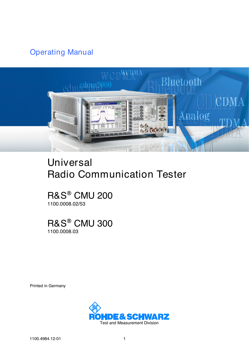
Operating Manual Universal Radio Communication Tester R&S CMU 200 1100.0008.02/53 R&S CMU 300 1100.0008.03 Printed in Germany Test and Measurement Division 1100.4984.12-01 1
R&S® is a registered trademark of Rohde & Schwarz GmbH & Co. KG. Trade names are trademarks of the owners.
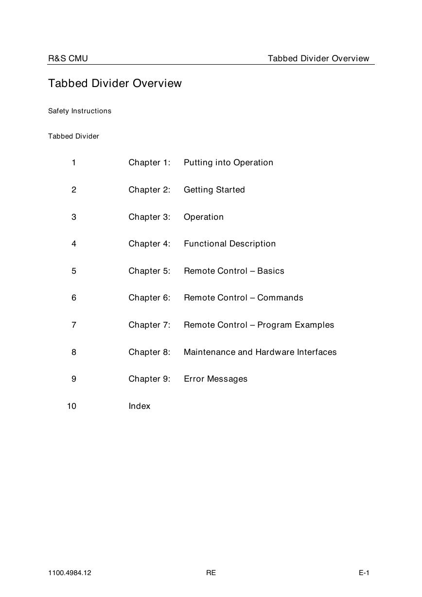
R&S CMU Tabbed Divider Overview Tabbed Divider Overview Safety Instructions Tabbed Divider 1 2 3 4 5 6 7 8 9 Chapter 1: Putting into Operation Chapter 2: Getting Started Chapter 3: Operation Chapter 4: Functional Description Chapter 5: Remote Control – Basics Chapter 6: Remote Control – Commands Chapter 7: Remote Control – Program Examples Chapter 8: Maintenance and Hardware Interfaces Chapter 9: Error Messages 10 Index 1100.4984.12 RE E-1
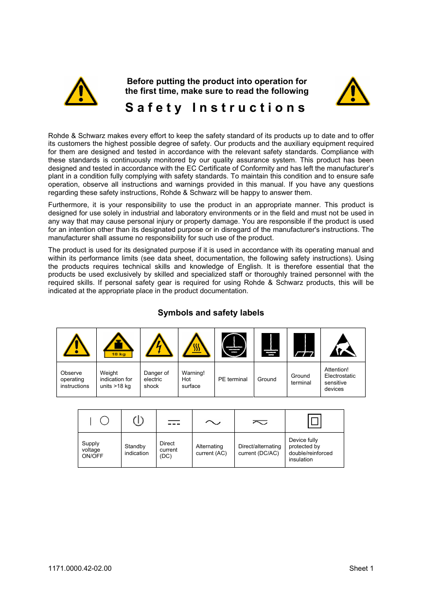
Before putting the product into operation for the first time, make sure to read the following S a f e t y I n s t r u c t i o n s Rohde & Schwarz makes every effort to keep the safety standard of its products up to date and to offer its customers the highest possible degree of safety. Our products and the auxiliary equipment required for them are designed and tested in accordance with the relevant safety standards. Compliance with these standards is continuously monitored by our quality assurance system. This product has been designed and tested in accordance with the EC Certificate of Conformity and has left the manufacturers plant in a condition fully complying with safety standards. To maintain this condition and to ensure safe operation, observe all instructions and warnings provided in this manual. If you have any questions regarding these safety instructions, Rohde & Schwarz will be happy to answer them. Furthermore, it is your responsibility to use the product in an appropriate manner. This product is designed for use solely in industrial and laboratory environments or in the field and must not be used in any way that may cause personal injury or property damage. You are responsible if the product is used for an intention other than its designated purpose or in disregard of the manufacturer’s instructions. The manufacturer shall assume no responsibility for such use of the product. The product is used for its designated purpose if it is used in accordance with its operating manual and within its performance limits (see data sheet, documentation, the following safety instructions). Using the products requires technical skills and knowledge of English. It is therefore essential that the products be used exclusively by skilled and specialized staff or thoroughly trained personnel with the required skills. If personal safety gear is required for using Rohde & Schwarz products, this will be indicated at the appropriate place in the product documentation. Symbols and safety labels Observe operating instructions Weight indication for units >18 kg Danger of electric shock Warning! Hot surface PE terminal Ground Ground terminal Attention! Electrostatic sensitive devices Supply voltage ON/OFF Standby indication Direct current (DC) Alternating current (AC) Direct/alternating current (DC/AC) Device fully protected by double/reinforced insulation 1171.0000.42-02.00 Sheet 1
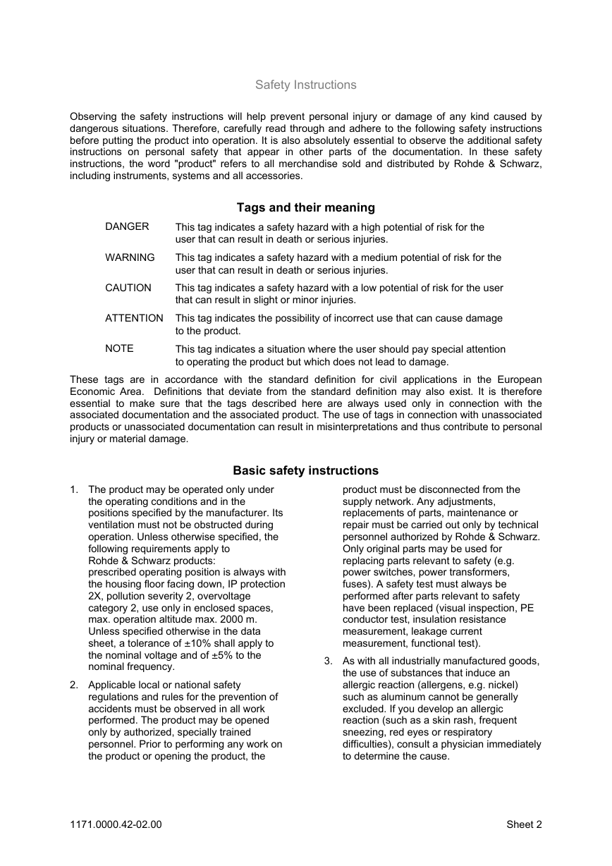
Safety Instructions Observing the safety instructions will help prevent personal injury or damage of any kind caused by dangerous situations. Therefore, carefully read through and adhere to the following safety instructions before putting the product into operation. It is also absolutely essential to observe the additional safety instructions on personal safety that appear in other parts of the documentation. In these safety instructions, the word "product" refers to all merchandise sold and distributed by Rohde & Schwarz, including instruments, systems and all accessories. Tags and their meaning DANGER WARNING CAUTION This tag indicates a safety hazard with a high potential of risk for the user that can result in death or serious injuries. This tag indicates a safety hazard with a medium potential of risk for the user that can result in death or serious injuries. This tag indicates a safety hazard with a low potential of risk for the user that can result in slight or minor injuries. ATTENTION This tag indicates the possibility of incorrect use that can cause damage to the product. This tag indicates a situation where the user should pay special attention to operating the product but which does not lead to damage. NOTE These tags are in accordance with the standard definition for civil applications in the European Economic Area. Definitions that deviate from the standard definition may also exist. It is therefore essential to make sure that the tags described here are always used only in connection with the associated documentation and the associated product. The use of tags in connection with unassociated products or unassociated documentation can result in misinterpretations and thus contribute to personal injury or material damage. Basic safety instructions 1. The product may be operated only under the operating conditions and in the positions specified by the manufacturer. Its ventilation must not be obstructed during operation. Unless otherwise specified, the following requirements apply to Rohde & Schwarz products: prescribed operating position is always with the housing floor facing down, IP protection 2X, pollution severity 2, overvoltage category 2, use only in enclosed spaces, max. operation altitude max. 2000 m. Unless specified otherwise in the data sheet, a tolerance of –10% shall apply to the nominal voltage and of –5% to the nominal frequency. 2. Applicable local or national safety regulations and rules for the prevention of accidents must be observed in all work performed. The product may be opened only by authorized, specially trained personnel. Prior to performing any work on the product or opening the product, the product must be disconnected from the supply network. Any adjustments, replacements of parts, maintenance or repair must be carried out only by technical personnel authorized by Rohde & Schwarz. Only original parts may be used for replacing parts relevant to safety (e.g. power switches, power transformers, fuses). A safety test must always be performed after parts relevant to safety have been replaced (visual inspection, PE conductor test, insulation resistance measurement, leakage current measurement, functional test). 3. As with all industrially manufactured goods, the use of substances that induce an allergic reaction (allergens, e.g. nickel) such as aluminum cannot be generally excluded. If you develop an allergic reaction (such as a skin rash, frequent sneezing, red eyes or respiratory difficulties), consult a physician immediately to determine the cause. 1171.0000.42-02.00 Sheet 2
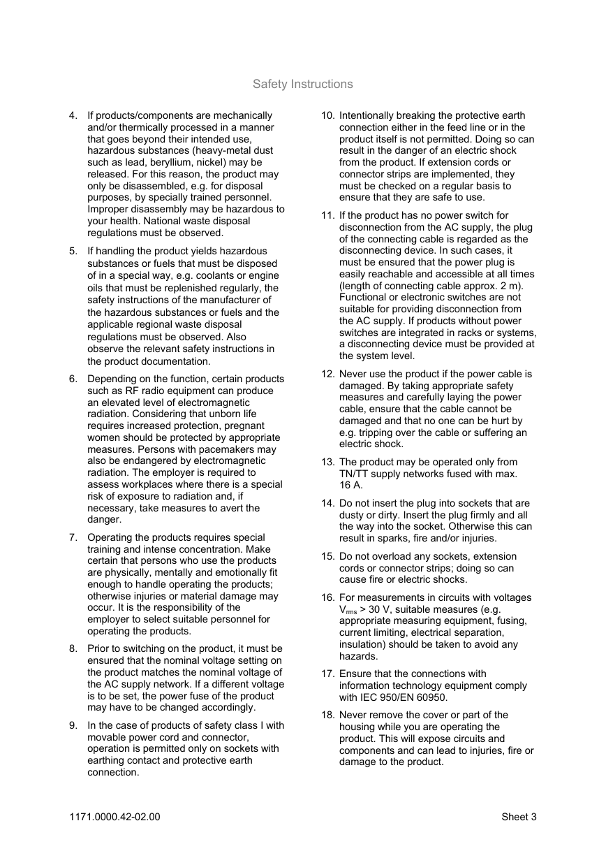
Safety Instructions 4. 5. If products/components are mechanically and/or thermically processed in a manner that goes beyond their intended use, hazardous substances (heavy-metal dust such as lead, beryllium, nickel) may be released. For this reason, the product may only be disassembled, e.g. for disposal purposes, by specially trained personnel. Improper disassembly may be hazardous to your health. National waste disposal regulations must be observed. If handling the product yields hazardous substances or fuels that must be disposed of in a special way, e.g. coolants or engine oils that must be replenished regularly, the safety instructions of the manufacturer of the hazardous substances or fuels and the applicable regional waste disposal regulations must be observed. Also observe the relevant safety instructions in the product documentation. 6. Depending on the function, certain products such as RF radio equipment can produce an elevated level of electromagnetic radiation. Considering that unborn life requires increased protection, pregnant women should be protected by appropriate measures. Persons with pacemakers may also be endangered by electromagnetic radiation. The employer is required to assess workplaces where there is a special risk of exposure to radiation and, if necessary, take measures to avert the danger. 7. Operating the products requires special training and intense concentration. Make certain that persons who use the products are physically, mentally and emotionally fit enough to handle operating the products; otherwise injuries or material damage may occur. It is the responsibility of the employer to select suitable personnel for operating the products. 8. Prior to switching on the product, it must be ensured that the nominal voltage setting on the product matches the nominal voltage of the AC supply network. If a different voltage is to be set, the power fuse of the product may have to be changed accordingly. In the case of products of safety class I with movable power cord and connector, operation is permitted only on sockets with earthing contact and protective earth connection. 9. 10. Intentionally breaking the protective earth connection either in the feed line or in the product itself is not permitted. Doing so can result in the danger of an electric shock from the product. If extension cords or connector strips are implemented, they must be checked on a regular basis to ensure that they are safe to use. 11. If the product has no power switch for disconnection from the AC supply, the plug of the connecting cable is regarded as the disconnecting device. In such cases, it must be ensured that the power plug is easily reachable and accessible at all times (length of connecting cable approx. 2 m). Functional or electronic switches are not suitable for providing disconnection from the AC supply. If products without power switches are integrated in racks or systems, a disconnecting device must be provided at the system level. 12. Never use the product if the power cable is damaged. By taking appropriate safety measures and carefully laying the power cable, ensure that the cable cannot be damaged and that no one can be hurt by e.g. tripping over the cable or suffering an electric shock. 13. The product may be operated only from TN/TT supply networks fused with max. 16 A. 14. Do not insert the plug into sockets that are dusty or dirty. Insert the plug firmly and all the way into the socket. Otherwise this can result in sparks, fire and/or injuries. 15. Do not overload any sockets, extension cords or connector strips; doing so can cause fire or electric shocks. 16. For measurements in circuits with voltages Vrms > 30 V, suitable measures (e.g. appropriate measuring equipment, fusing, current limiting, electrical separation, insulation) should be taken to avoid any hazards. 17. Ensure that the connections with information technology equipment comply with IEC 950/EN 60950. 18. Never remove the cover or part of the housing while you are operating the product. This will expose circuits and components and can lead to injuries, fire or damage to the product. 1171.0000.42-02.00 Sheet 3
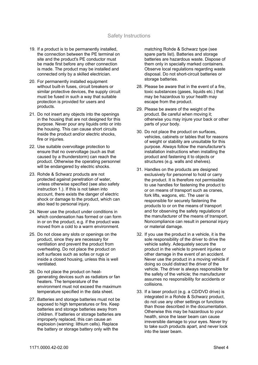
Safety Instructions 19. If a product is to be permanently installed, the connection between the PE terminal on site and the product’s PE conductor must be made first before any other connection is made. The product may be installed and connected only by a skilled electrician. 20. For permanently installed equipment without built-in fuses, circuit breakers or similar protective devices, the supply circuit must be fused in such a way that suitable protection is provided for users and products. 21. Do not insert any objects into the openings in the housing that are not designed for this purpose. Never pour any liquids onto or into the housing. This can cause short circuits inside the product and/or electric shocks, fire or injuries. 22. Use suitable overvoltage protection to ensure that no overvoltage (such as that caused by a thunderstorm) can reach the product. Otherwise the operating personnel will be endangered by electric shocks. 23. Rohde & Schwarz products are not protected against penetration of water, unless otherwise specified (see also safety instruction 1.). If this is not taken into account, there exists the danger of electric shock or damage to the product, which can also lead to personal injury. 24. Never use the product under conditions in which condensation has formed or can form in or on the product, e.g. if the product was moved from a cold to a warm environment. 25. Do not close any slots or openings on the product, since they are necessary for ventilation and prevent the product from overheating. Do not place the product on soft surfaces such as sofas or rugs or inside a closed housing, unless this is well ventilated. 26. Do not place the product on heat- generating devices such as radiators or fan heaters. The temperature of the environment must not exceed the maximum temperature specified in the data sheet. 27. Batteries and storage batteries must not be exposed to high temperatures or fire. Keep batteries and storage batteries away from children. If batteries or storage batteries are improperly replaced, this can cause an explosion (warning: lithium cells). Replace the battery or storage battery only with the matching Rohde & Schwarz type (see spare parts list). Batteries and storage batteries are hazardous waste. Dispose of them only in specially marked containers. Observe local regulations regarding waste disposal. Do not short-circuit batteries or storage batteries. 28. Please be aware that in the event of a fire, toxic substances (gases, liquids etc.) that may be hazardous to your health may escape from the product. 29. Please be aware of the weight of the product. Be careful when moving it; otherwise you may injure your back or other parts of your body. 30. Do not place the product on surfaces, vehicles, cabinets or tables that for reasons of weight or stability are unsuitable for this purpose. Always follow the manufacturer’s installation instructions when installing the product and fastening it to objects or structures (e.g. walls and shelves). 31. Handles on the products are designed exclusively for personnel to hold or carry the product. It is therefore not permissible to use handles for fastening the product to or on means of transport such as cranes, fork lifts, wagons, etc. The user is responsible for securely fastening the products to or on the means of transport and for observing the safety regulations of the manufacturer of the means of transport. Noncompliance can result in personal injury or material damage. 32. If you use the product in a vehicle, it is the sole responsibility of the driver to drive the vehicle safely. Adequately secure the product in the vehicle to prevent injuries or other damage in the event of an accident. Never use the product in a moving vehicle if doing so could distract the driver of the vehicle. The driver is always responsible for the safety of the vehicle; the manufacturer assumes no responsibility for accidents or collisions. 33. If a laser product (e.g. a CD/DVD drive) is integrated in a Rohde & Schwarz product, do not use any other settings or functions than those described in the documentation. Otherwise this may be hazardous to your health, since the laser beam can cause irreversible damage to your eyes. Never try to take such products apart, and never look into the laser beam. 1171.0000.42-02.00 Sheet 4
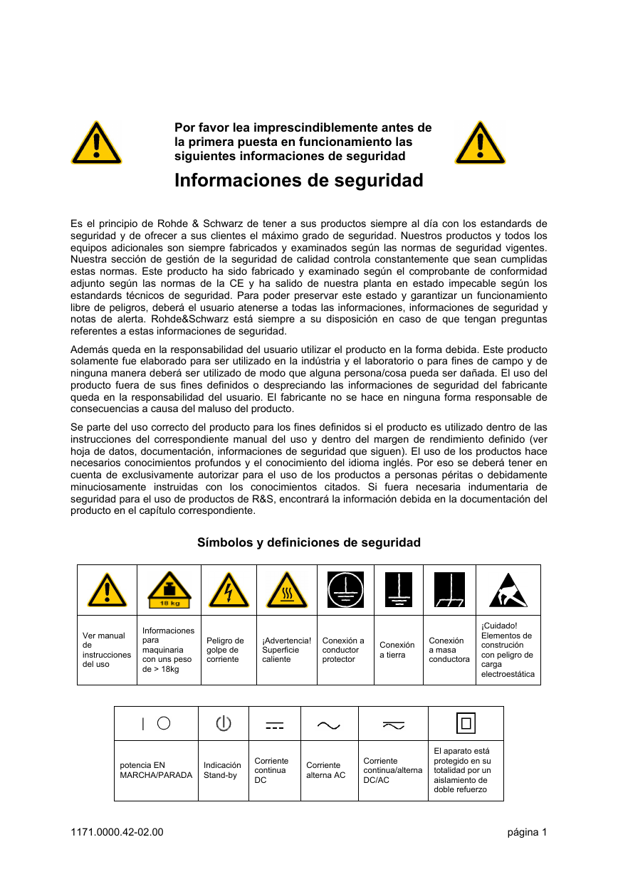
Por favor lea imprescindiblemente antes de la primera puesta en funcionamiento las siguientes informaciones de seguridad Informaciones de seguridad Es el principio de Rohde & Schwarz de tener a sus productos siempre al da con los estandards de seguridad y de ofrecer a sus clientes el mÆximo grado de seguridad. Nuestros productos y todos los equipos adicionales son siempre fabricados y examinados segœn las normas de seguridad vigentes. Nuestra seccin de gestin de la seguridad de calidad controla constantemente que sean cumplidas estas normas. Este producto ha sido fabricado y examinado segœn el comprobante de conformidad adjunto segœn las normas de la CE y ha salido de nuestra planta en estado impecable segœn los estandards tØcnicos de seguridad. Para poder preservar este estado y garantizar un funcionamiento libre de peligros, deberÆ el usuario atenerse a todas las informaciones, informaciones de seguridad y notas de alerta. Rohde&Schwarz estÆ siempre a su disposicin en caso de que tengan preguntas referentes a estas informaciones de seguridad. AdemÆs queda en la responsabilidad del usuario utilizar el producto en la forma debida. Este producto solamente fue elaborado para ser utilizado en la indœstria y el laboratorio o para fines de campo y de ninguna manera deberÆ ser utilizado de modo que alguna persona/cosa pueda ser daæada. El uso del producto fuera de sus fines definidos o despreciando las informaciones de seguridad del fabricante queda en la responsabilidad del usuario. El fabricante no se hace en ninguna forma responsable de consecuencias a causa del maluso del producto. Se parte del uso correcto del producto para los fines definidos si el producto es utilizado dentro de las instrucciones del correspondiente manual del uso y dentro del margen de rendimiento definido (ver hoja de datos, documentacin, informaciones de seguridad que siguen). El uso de los productos hace necesarios conocimientos profundos y el conocimiento del idioma inglØs. Por eso se deberÆ tener en cuenta de exclusivamente autorizar para el uso de los productos a personas pØritas o debidamente minuciosamente instruidas con los conocimientos citados. Si fuera necesaria indumentaria de seguridad para el uso de productos de R&S, encontrarÆ la informacin debida en la documentacin del producto en el captulo correspondiente. Smbolos y definiciones de seguridad Ver manual de instrucciones del uso Informaciones para maquinaria con uns peso de > 18kg Peligro de golpe de corriente ¡Advertencia! Superficie caliente Conexin a conductor protector Conexin a tierra Conexin a masa conductora ¡Cuidado! Elementos de construcin con peligro de carga electroestÆtica potencia EN MARCHA/PARADA Indicacin Stand-by Corriente continua DC Corriente alterna AC Corriente continua/alterna DC/AC El aparato estÆ protegido en su totalidad por un aislamiento de doble refuerzo 1171.0000.42-02.00 pÆgina 1
分享到:
收藏