SAMSUNG CONFIDENTIAL
Rev. 1.0, Jul. 2015
KLMxGxJENB-B041
Samsung eMMC Product family
eMMC 5.1 Specification compatibility
datasheet
SAMSUNG ELECTRONICS RESERVES THE RIGHT TO CHANGE PRODUCTS, INFORMATION AND
SPECIFICATIONS WITHOUT NOTICE.
Products and specifications discussed herein are for reference purposes only. All information discussed
herein is provided on an "AS IS" basis, without warranties of any kind.
This document and all information discussed herein remain the sole and exclusive property of Samsung
Electronics. No license of any patent, copyright, mask work, trademark or any other intellectual property
right is granted by one party to the other party under this document, by implication, estoppel or other-
wise.
Samsung products are not intended for use in life support, critical care, medical, safety equipment, or
similar applications where product failure could result in loss of life or personal or physical harm, or any
military or defense application, or any governmental procurement to which special terms or provisions
may apply.
For updates or additional information about Samsung products, contact your nearest Samsung office.
All brand names, trademarks and registered trademarks belong to their respective owners.
ⓒ 2015 Samsung Electronics Co., Ltd. All rights reserved.
- 1 -
�
datasheet
SAMSUNG CONFIDENTIAL
Rev. 1.0
eMMC
KLMxGxJENB-B041
Revision History
Revision No.
History
0.0
1.0
1. Initial issue
1. Customer Sample
Draft Date
Remark
Editor
Jun. 10, 2015
Target
Jul. 15, 2015
Final
S.M.Lee
S.M.Lee
IF THERE IS ANY OTHER OPERATION TO IMPLEMENT IN ADDITION TO SPECIFICATION
IN THE DATASHEET OR JEDEC STANDARD, PLEASE CONTACT EACH BRANCH OFFICE OR
HEADQUARTERS OF SAMSUNG ELECTRONICS.
- 2 -
�
KLMxGxJENB-B041
Table Of Contents
datasheet
SAMSUNG CONFIDENTIAL
Rev. 1.0
eMMC
1.0 PRODUCT LIST..........................................................................................................................................................4
2.0 KEY FEATURES.........................................................................................................................................................4
3.0 PACKAGE CONFIGURATIONS .................................................................................................................................5
3.1 153 Ball Pin Configuration ....................................................................................................................................... 5
3.1.1 11.5mm x 13mm x 0.8mm Package Dimension ............................................................................................... 6
3.1.2 11.5mm x 13mm x 1.0mm Package Dimension ............................................................................................... 6
3.1.3 11.5mm x 13mm x 1.2mm Package Dimension ............................................................................................... 7
3.2 Product Architecture ................................................................................................................................................ 8
4.0 HS400 mode...............................................................................................................................................................9
5.0 New eMMC5.1 Features .............................................................................................................................................10
5.1 Overview.................................................................................................................................................................. 10
5.2 Command Queuing ................................................................................................................................................. 10
5.2.1 CMD Set Description......................................................................................................................................... 10
5.2.2 New Response : QSR (Queue Status Register) .............................................................................................. 10
5.2.3 Send Status : CMD13 ...................................................................................................................................... 10
5.2.4 Mechanism of CMD Queue operation............................................................................................................... 11
5.2.5 CMD Queue Register description ..................................................................................................................... 11
5.3 Enhanced Strobe Mode........................................................................................................................................... 11
5.4 RPMB Throughput improve ..................................................................................................................................... 11
5.5 Secure Write Protection........................................................................................................................................... 12
6.0 Technical Notes ..........................................................................................................................................................13
6.1 S/W Algorithm.......................................................................................................................................................... 13
6.1.1 Partition Management ....................................................................................................................................... 13
6.1.1.1 Boot Area Partition and RPMB Area Partition ............................................................................................ 13
6.1.1.2 Enhanced Partition (Area) .......................................................................................................................... 13
6.1.2 Boot operation................................................................................................................................................... 14
6.1.3 User Density...................................................................................................................................................... 15
6.1.4 Auto Power Saving Mode.................................................................................................................................. 15
6.1.5 Performance...................................................................................................................................................... 16
7.0 REGISTER VALUE.....................................................................................................................................................17
7.1 OCR Register .......................................................................................................................................................... 17
7.2 CID Register ............................................................................................................................................................ 17
7.2.1 Product name table (In CID Register) ............................................................................................................... 17
7.3 CSD Register........................................................................................................................................................... 18
7.4 Extended CSD Register .......................................................................................................................................... 19
8.0 AC PARAMETER........................................................................................................................................................24
8.1 Timing Parameter .................................................................................................................................................... 24
8.2 Previous Bus Timing Parameters for DDR52 and HS200 mode are defined by JEDEC standard.......................... 24
8.3 Bus Timing Specification in HS400 mode ............................................................................................................... 24
8.3.1 HS400 Device Input Timing .............................................................................................................................. 24
8.3.2 HS400 Device Output Timing............................................................................................................................ 25
8.4 Bus signal levels...................................................................................................................................................... 26
8.4.1 Open-drain mode bus signal level..................................................................................................................... 26
8.4.2 Push-pull mode bus signal level eMMC ............................................................................................................ 26
9.0 DC PARAMETER .......................................................................................................................................................27
9.1 Active Power Consumption during operation .......................................................................................................... 27
9.2 Standby Power Consumption in auto power saving mode and standby state........................................................ 27
9.3 Sleep Power Consumption in Sleep State.............................................................................................................. 27
9.4 Bus Signal Line Load............................................................................................................................................... 28
IF THERE IS ANY OTHER OPERATION TO IMPLEMENT IN ADDITION TO SPECIFICATION
IN THE DATASHEET OR JEDEC STANDARD, PLEASE CONTACT EACH BRANCH OFFICE OR
HEADQUARTERS OF SAMSUNG ELECTRONICS.
- 3 -
�
KLMxGxJENB-B041
datasheet
INTRODUCTION
SAMSUNG CONFIDENTIAL
Rev. 1.0
eMMC
SAMSUNG eMMC is an embedded MMC solution designed in a BGA package form. eMMC operation is identical to a MMC device and therefore is a sim-
ple read and write to memory using MMC protocol v5.1 which is a industry standard.
eMMC consists of NAND flash and a MMC controller. 3V supply voltage is required for the NAND area (VDDF or VCC) whereas 1.8V or 3V dual supply
voltage (VDD or VCCQ) is supported for the MMC controller. SAMSUNG eMMC supports 200MHz DDR – up to 400MBps with bus widths of 8 bit in order
to improve sequential bandwidth, especially sequential read performance.
There are several advantages of using eMMC. It is easy to use as the MMC interface allows easy integration with any microprocessor with MMC host.
Any revision or amendment of NAND is invisible to the host as the embedded MMC controller insulates NAND technology from the host. This leads to
faster product development as well as faster times to market.
The embedded flash management software or FTL(Flash Transition Layer) of eMMC manages Wear Leveling, Bad Block Management and ECC. The
FTL supports all features of the Samsung NAND flash and achieves optimal performance.
1.0 PRODUCT LIST
[Table 1] Product List
Capacities
eMMC Part ID
16 GB
32 GB
64 GB
128 GB
KLMAG1JENB-B041
KLMBG2JENB-B041
KLMCG4JENB-B041
KLMDG8JENB-B041
NAND Flash Type User Density (%)
128Gb MLC x 1
128Gb MLC x 2
128Gb MLC x 4
128Gb MLC x 8
91.0%
2.0 KEY FEATURES
embedded MultiMediaCard Ver. 5.1 compatible.
Power System
Package size
Pin Configuration
- Interface power :
VDD (1.70V ~ 1.95V or
2.7V ~ 3.6V)
- Memory power :
VDDF (2.7V ~ 3.6V)
11.5mm x 13mm x 0.8mm
11.5mm x 13mm x 1.0mm
153FBGA
11.5mm x 13mm x 1.2mm
SAMSUNG eMMC supports features of eMMC5.1 which are defined in JEDEC Standard
- Supported Features : Packed command, Cache, Discard, Sanitize, Power Off Notification, Data Tag,
Partition types, Context ID, Real Time Clock, Dynamic Device Capacity, Command Queuing, Enhanced Strobe Mode,
Secure Write Protection, HS200, HS400, Field Firmware Update.
- Non-supported Features : Large Sector Size (4KB)
Full backward compatibility with previous MultiMediaCard system specification (1bit data bus, multi-eMMC systems)
Data bus width : 1bit (Default), 4bit and 8bit
MMC I/F Clock Frequency : 0 ~ 200MHz
MMC I/F Boot Frequency : 0 ~ 52MHz
Temperature : Operation (-25C ~ 85C), Storage without operation (-40C ~ 85C)
Power : Interface power → VDD(VCCQ) (1.70V ~ 1.95V or 2.7V ~ 3.6V) , Memory power → VDDF(VCC) (2.7V ~ 3.6V)
IF THERE IS ANY OTHER OPERATION TO IMPLEMENT IN ADDITION TO SPECIFICATION
IN THE DATASHEET OR JEDEC STANDARD, PLEASE CONTACT EACH BRANCH OFFICE OR
HEADQUARTERS OF SAMSUNG ELECTRONICS.
- 4 -
�
datasheet
SAMSUNG CONFIDENTIAL
Rev. 1.0
eMMC
KLMxGxJENB-B041
3.0 PACKAGE CONFIGURATIONS
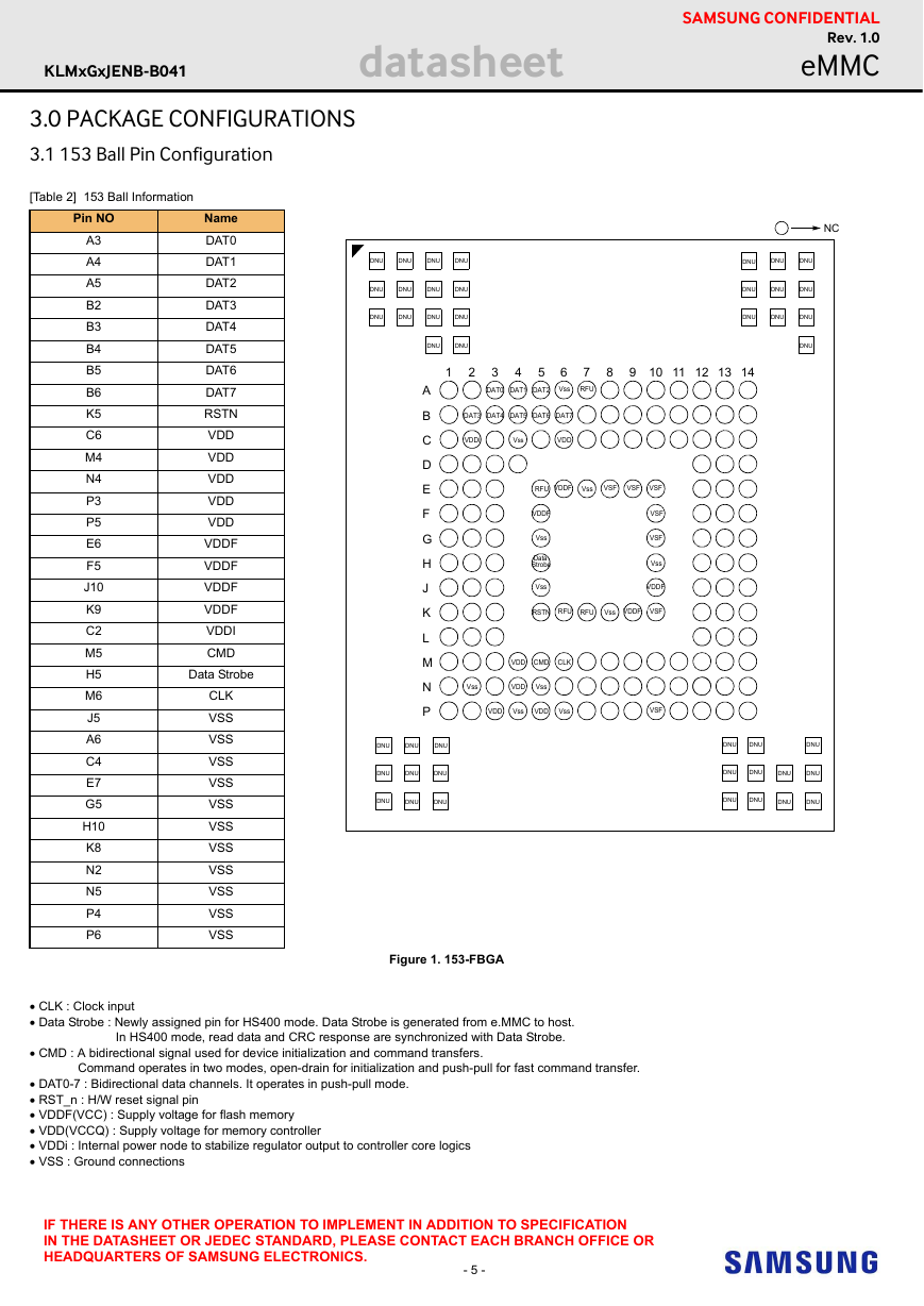
3.1 153 Ball Pin Configuration
[Table 2] 153 Ball Information
DNU
DNU
DNU
DNU
DNU
DNU
DNU
DNU
DNU
DNU
DNU
DNU
DNU
DNU
NC
DNU
DNU
DNU
DNU
DNU
DNU
DNU
DNU
DNU
DNU
1
2
3
DAT0
4
DAT1
5
DAT2
6
Vss
7
RFU
8
9 10 11 12 13 14
DAT3
DAT4
DAT5
DAT6
DAT7
VDDI
Vss
VDD
RFU
VDDF
Vss
VSF
VSF
VSF
VDDF
Vss
Data
Strobe
Vss
VSF
VSF
Vss
VDDF
RSTN
RFU
RFU
Vss
VDDF
VSF
VDD
CMD
CLK
Vss
VDD
Vss
VDD
Vss
VDD
Vss
VSF
A
B
C
D
E
F
G
H
J
K
L
M
N
P
DNU
DNU
DNU
DNU
DNU
DNU
DNU
DNU
DNU
DNU
DNU
DNU
DNU
DNU
DNU
DNU
DNU
DNU
DNU
DNU
Pin NO
A3
A4
A5
B2
B3
B4
B5
B6
K5
C6
M4
N4
P3
P5
E6
F5
J10
K9
C2
M5
H5
M6
J5
A6
C4
E7
G5
H10
K8
N2
N5
P4
P6
Name
DAT0
DAT1
DAT2
DAT3
DAT4
DAT5
DAT6
DAT7
RSTN
VDD
VDD
VDD
VDD
VDD
VDDF
VDDF
VDDF
VDDF
VDDI
CMD
Data Strobe
CLK
VSS
VSS
VSS
VSS
VSS
VSS
VSS
VSS
VSS
VSS
VSS
Figure 1. 153-FBGA
CLK : Clock input
Data Strobe : Newly assigned pin for HS400 mode. Data Strobe is generated from e.MMC to host.
In HS400 mode, read data and CRC response are synchronized with Data Strobe.
CMD : A bidirectional signal used for device initialization and command transfers.
Command operates in two modes, open-drain for initialization and push-pull for fast command transfer.
DAT0-7 : Bidirectional data channels. It operates in push-pull mode.
RST_n : H/W reset signal pin
VDDF(VCC) : Supply voltage for flash memory
VDD(VCCQ) : Supply voltage for memory controller
VDDi : Internal power node to stabilize regulator output to controller core logics
VSS : Ground connections
IF THERE IS ANY OTHER OPERATION TO IMPLEMENT IN ADDITION TO SPECIFICATION
IN THE DATASHEET OR JEDEC STANDARD, PLEASE CONTACT EACH BRANCH OFFICE OR
HEADQUARTERS OF SAMSUNG ELECTRONICS.
- 5 -
�
KLMxGxJENB-B041
datasheet
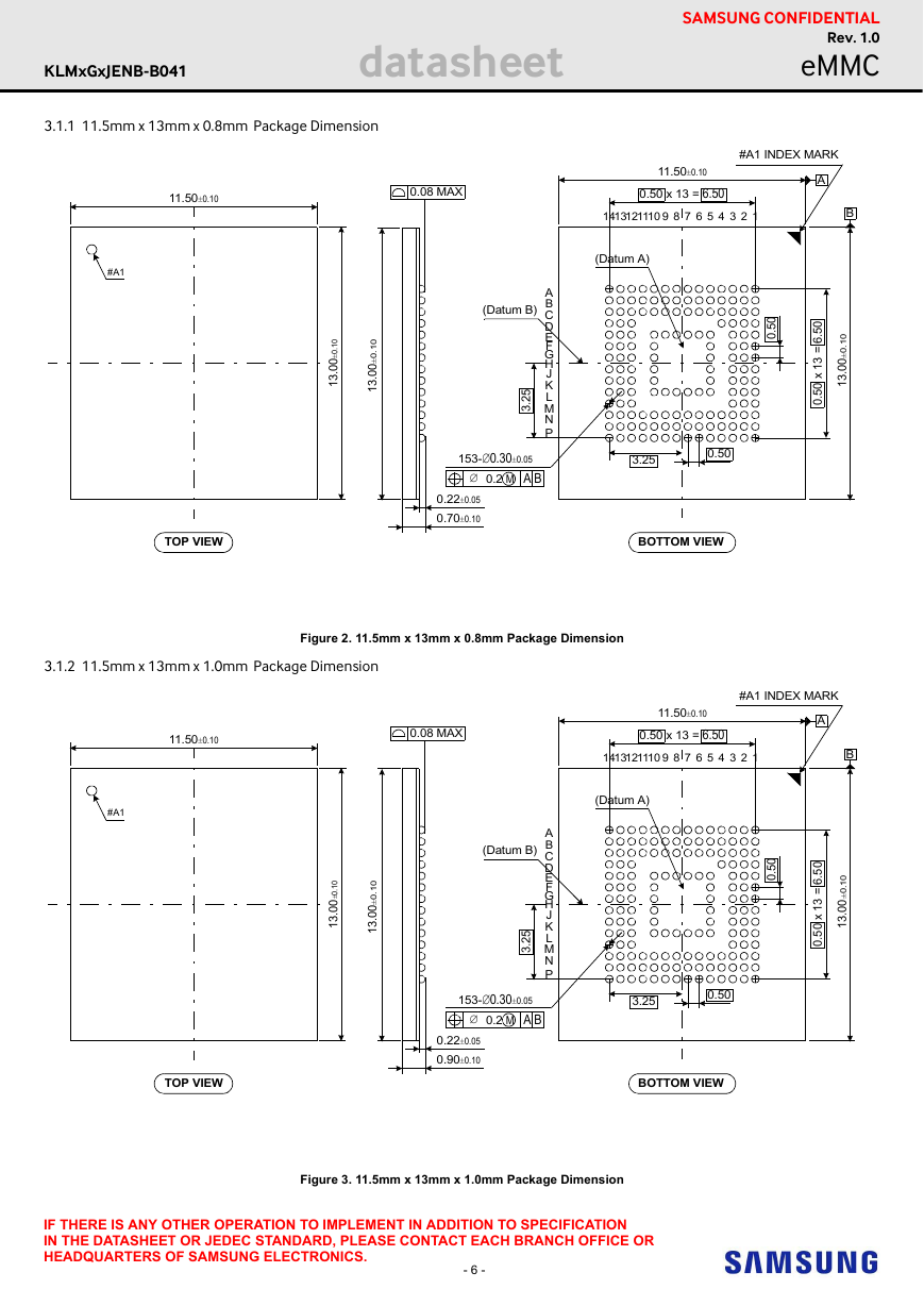
3.1.1 11.5mm x 13mm x 0.8mm Package Dimension
11.50±0.10
0.08 MAX
SAMSUNG CONFIDENTIAL
Rev. 1.0
eMMC
11.50±0.10
0.50 x 13 = 6.50
11
4
7 6 5
89
14
1312 10
#A1 INDEX MARK
A
B
3
2
1
#A1
(Datum A)
.
0
1
0
±
0
0
3
1
.
.
0
1
0
±
0
0
3
1
.
(Datum B)
5
2
3
.
A
B
C
D
E
F
G
H
J
K
L
M
N
P
0
5
.
0
.
0
5
6
=
3
1
x
0
5
.
0
.
0
1
0
±
0
0
3
1
.
153-0.30±0.05
3.25
0.50
0.2 M A B
0.22±0.05
0.70±0.10
TOP VIEW
BOTTOM VIEW
3.1.2 11.5mm x 13mm x 1.0mm Package Dimension
Figure 2. 11.5mm x 13mm x 0.8mm Package Dimension
11.50±0.10
11.50±0.10
0.08 MAX
0.50 x 13 = 6.50
11
4
7 6 5
89
14
1312 10
#A1 INDEX MARK
A
B
3
2
1
0
5
.
6
=
3
1
x
0
5
.
0
.
0
1
0
±
0
0
.
3
1
#A1
(Datum A)
.
0
1
0
±
0
0
.
3
1
.
0
1
0
±
0
0
.
3
1
(Datum B)
5
2
.
3
A
B
C
D
E
F
G
H
J
K
L
M
N
P
0
5
.
0
153-0.30±0.05
3.25
0.50
0.2 M A B
0.22±0.05
0.90±0.10
TOP VIEW
BOTTOM VIEW
Figure 3. 11.5mm x 13mm x 1.0mm Package Dimension
IF THERE IS ANY OTHER OPERATION TO IMPLEMENT IN ADDITION TO SPECIFICATION
IN THE DATASHEET OR JEDEC STANDARD, PLEASE CONTACT EACH BRANCH OFFICE OR
HEADQUARTERS OF SAMSUNG ELECTRONICS.
- 6 -
�
KLMxGxJENB-B041
datasheet
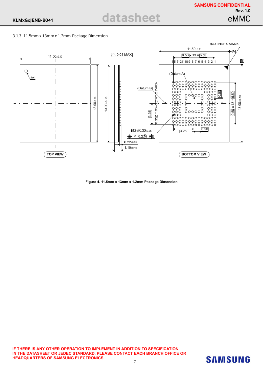
3.1.3 11.5mm x 13mm x 1.2mm Package Dimension
11.50±0.10
0.08 MAX
SAMSUNG CONFIDENTIAL
Rev. 1.0
eMMC
11.50±0.10
0.50 x 13 = 6.50
11
4
7 6 5
89
14
1312 10
#A1 INDEX MARK
A
B
3
2
1
.
0
5
6
=
3
1
x
0
5
.
0
.
0
1
0
±
0
0
3
1
.
#A1
(Datum A)
.
0
1
0
±
0
0
3
1
.
.
0
1
0
±
0
0
3
1
.
(Datum B)
5
2
3
.
A
B
C
D
E
F
G
H
J
K
L
M
N
P
0
5
.
0
153-0.30±0.05
3.25
0.50
0.2 M A B
0.22±0.05
1.10±0.10
TOP VIEW
BOTTOM VIEW
Figure 4. 11.5mm x 13mm x 1.2mm Package Dimension
IF THERE IS ANY OTHER OPERATION TO IMPLEMENT IN ADDITION TO SPECIFICATION
IN THE DATASHEET OR JEDEC STANDARD, PLEASE CONTACT EACH BRANCH OFFICE OR
HEADQUARTERS OF SAMSUNG ELECTRONICS.
- 7 -
�
KLMxGxJENB-B041
datasheet
SAMSUNG CONFIDENTIAL
Rev. 1.0
eMMC
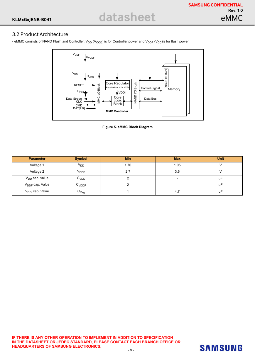
3.2 Product Architecture
- eMMC consists of NAND Flash and Controller. VDD (VCCQ) is for Controller power and VDDF (VCC)is for flash power
l
k
c
o
B
O
/
I
D
N
A
N
VDDF
CVDDF
VDD
CVDD
RESET
CReg
Data Strobe
CLK
CMD
DAT[7:0]
l
k
c
o
B
O
/
I
C
M
M
Core Regulator
(Required for 3.3V VDD)
VDDi
Core
Logic
Block
MMC Controller
l
k
c
o
B
O
/
I
D
N
A
N
Control Signal
Data Bus
Figure 5. eMMC Block Diagram
Parameter
Voltage 1
Voltage 2
VDD cap. value
VDDF cap. Value
VDDi cap. Value
Symbol
VDD
VDDF
CVDD
CVDDF
CReg
Min
1.70
2.7
2
2
1
Memory
Max
1.95
3.6
-
-
4.7
Unit
V
V
uF
uF
uF
IF THERE IS ANY OTHER OPERATION TO IMPLEMENT IN ADDITION TO SPECIFICATION
IN THE DATASHEET OR JEDEC STANDARD, PLEASE CONTACT EACH BRANCH OFFICE OR
HEADQUARTERS OF SAMSUNG ELECTRONICS.
- 8 -
�



 2023年江西萍乡中考道德与法治真题及答案.doc
 2012年重庆南川中考生物真题及答案.doc
 2013年江西师范大学地理学综合及文艺理论基础考研真题.doc
 2020年四川甘孜小升初语文真题及答案I卷.doc
 2020年注册岩土工程师专业基础考试真题及答案.doc
 2023-2024学年福建省厦门市九年级上学期数学月考试题及答案.doc
 2021-2022学年辽宁省沈阳市大东区九年级上学期语文期末试题及答案.doc
 2022-2023学年北京东城区初三第一学期物理期末试卷及答案.doc
 2018上半年江西教师资格初中地理学科知识与教学能力真题及答案.doc
 2012年河北国家公务员申论考试真题及答案-省级.doc
 2020-2021学年江苏省扬州市江都区邵樊片九年级上学期数学第一次质量检测试题及答案.doc
 2022下半年黑龙江教师资格证中学综合素质真题及答案.doc