52
IEEE JOURNAL OF OCEANIC ENGINEERING, VOL. 25, NO. 1, JANUARY 2000
A Computationally Efficient Doppler Compensation
System for Underwater Acoustic Communications
Bayan S. Sharif, Member, IEEE, Jeff Neasham, Oliver R. Hinton, and Alan E. Adams
Abstract—A Doppler compensation system is presented which
is suitable for high-data-rate acoustic communication between
rapidly moving platforms such as autonomous underwater
vehicles. The proposed approach provides a generic preprocessor
to conventional adaptive receiver structures with only a mar-
ginal increase in computational load and hardware cost. The
preprocessor employs a novel Doppler estimation technique and
efficient sample rate conversion to remove Doppler shift induced
by platform velocity and acceleration. Performance predicted by
simulation is compared to that of sea trials of a prototype com-
munication system in the North Sea. Successful communication
is demonstrated at 16 kbit/s with a transmitting platform moving
at up to ± 2.6 m/s.
Index Terms—Acoustic telemetry, carrier phase, linear interpo-
lation, symbol synchronization.
I. INTRODUCTION
communication,
I N UNDERWATER acoustic
carrier
tracking and symbol synchronization are adversely affected
by Doppler. The low velocity of acoustic waves (~ 1500 m/s)
and the use of wide-band modulation result in Doppler shifts
several orders of magnitude greater than those experienced
in EM transmission. Relative motion of the transmitting and
receiving elements is usually unavoidable, particularly if either
end of the link is deployed by a surface vessel which is subject
to the effects of sea currents and/or surface waves. Rapidly
moving platforms such as autonomous underwater vehicles
(AUV’s) present a more serious problem. Compensating for
Doppler shifts resulting from relative velocities up to 10 m/s is
far beyond the capability of conventional adaptive equalization
structures, even with explicit phase tracking loops [1]. This
paper presents a novel approach based on a Doppler prepro-
cessing structure, compatible with existing adaptive receiver
structures, to deal with these severe Doppler effects.
The relative Doppler shift
is defined as the ratio of the
source relative velocity ( ) to the propagation wave velocity ( ).
, the Doppler effect can be
For a single-frequency component
expressed as a frequency scaling
frequency as the carrier. The Doppler shift imposed on the car-
rier is dealt with by carrier synchronization, which is equivalent
to adjusting the local carrier frequency. Conventionally, this is
th law carrier recovery and/or a phase-locked
achieved using
loop (PLL) [2], [3].
In wide-band signals, Doppler translates each frequency com-
ponent by a different amount, and the Doppler effect is more
accurately modeled as a complete time scaling (expansion or
compression) of the signal waveform
(2)
and
are the source and Doppler-shifted received
where
signals, respectively. This wide-band model of the Doppler
effect is used for underwater acoustic communications where
the bandwidth can be as high as an octave (e.g., 10–20-kHz
band). In this case, symbol synchronization is of equal impor-
tance to carrier synchronization. Furthermore, conventional
synchronization techniques, such as PLL’s when coupled
with equalization, are often unreliable in underwater acoustic
communications, mainly due to severe multipath distortion and
fading [1]. Also, in the PLL, the error loop filter bandwidth
required to track Doppler shifts as high as 1% is very difficult
to achieve.
, where
is an integer and
If we now consider a discrete-time sampled source signal
is the sampling period,
then introducing a Doppler shift to the received signal in (2) is
equivalent to a scaling of the sampling period (interpolation or
decimation)
(3)
) is known, then the received
If the amount of Doppler shift (
signal can be compressed/expanded by inverse time scaling
to remove both carrier and symbol shift. In a multirate dis-
crete-time processing system, this is equivalent to resampling
the bandpass signal by 1+
(1)
(4)
This is often used as an approximation for narrow-band signals
in which the whole signal spectrum is translated by the same
Removal of the fractional Doppler shift
then corresponds to a scaling of the sampling frequency
from a received signal
Manuscript received October 15, 1998; revised June 22, 1999. This work was
supported by the CMPT/EPSRC Managed TUUV Programme (Technology for
Unmanned Underwater Vehicles) through a research grant.
The authors are with the Department of Electrical and Electronic Engineering,
University of Newcastle, Newcastle upon Tyne, NE1 7RU, U.K.
Publisher Item Identifier S 0364-9059(00)00291-0.
This Doppler compensation approach implies a two-stage
process; first the Doppler shift must be estimated from the
.
received signal to obtain the interpolation factor
An interpolator structure is then used to perform a sampling
(5)
0364–9059/00$10.00 © 2000 IEEE
�
SHARIF et al.: A DOPPLER COMPENSATION SYSTEM FOR UNDERWATER ACOUSTIC COMMUNICATIONS
53
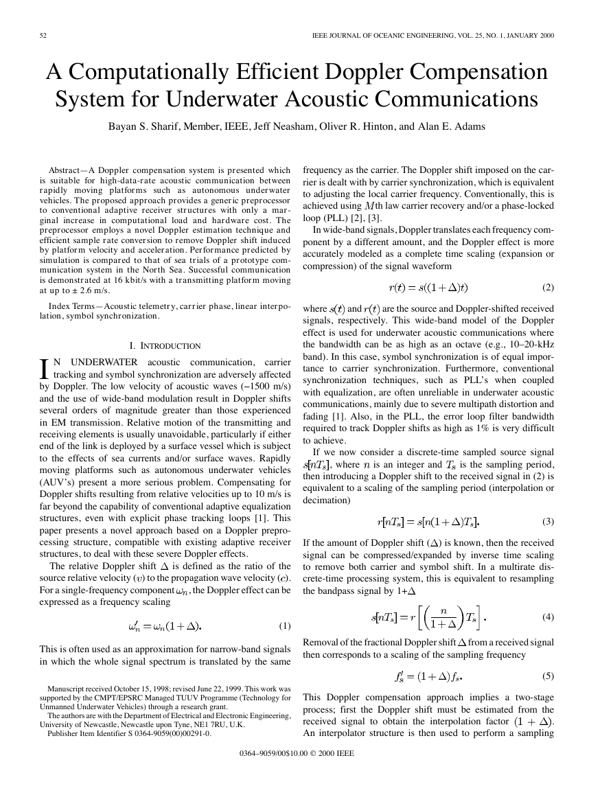
Fig. 1. Doppler estimation/compensation structure.
rate conversion on the incoming samples. The overall system
structure is shown in Fig. 1. This approach provides a generic
preprocessor that can be used with wide-band receiver struc-
tures. The interpolator structure can be used either prior to
(bandpass) or after demodulation (baseband). For a com-
plex baseband interpolator structure,
the carrier frequency
offset must be removed prior to demodulation. Baseband
interpolation offers a considerable computational
saving
for relatively narrow-band signals; however, for underwater
acoustic telemetry characterized by wide-band modulation
(octave bandwidth), this saving is marginal.
A major design parameter is the degree of accuracy required
from the Doppler estimator and interpolator, which is entirely
dependent on the amount of residual Doppler that can be toler-
ated by the receiver/demodulator system. Doppler tolerance of
decision feedback equalizers (DFE)’s with an embedded PLL
is related to the equalizer’s tracking rate, adaptation algorithm,
and the phase-tracking loop gain. The DFE is used to track slow
channel variations and can only tolerate small levels of Doppler
shift whilst maintaining a low mean square error (MSE). At in-
creased levels of Doppler, the DFE is unable to track the fast
phase variations, which results in increased MSE, or even equal-
izer divergence. Previous experimental trials have shown that,
for a bandwidth of 10 kHz, such a DFE structure could tolerate
fractional Doppler shifts of the order of 10- 4 [1]. This suggests
that the Doppler estimator and interpolator must be accurate to
within a factor of 10- 4 to allow successful communications with
such a receiver.
To summarize, the focus of this paper is on the development
of a digital signalprocessing (DSP) algorithm to accurately esti-
mate time expansion/compression and then remove the Doppler
shift by efficient multirate sampling. The paper is organized as
follows. Section II presents Doppler estimation and interpola-
tion methods for Doppler compensation. The effects of platform
acceleration are discussed in Section III. Section IV provides de-
tails of the sea trial system design, simulation and experimental
results. Finally, conclusions are drawn in Section V.
II. DOPPLER ESTIMATION AND COMPENSATION TECHNIQUES
A. Ambiguity Function Method
The ambiguity function shows the matched filter response
against delay and Doppler shift variations of the incoming signal
[4]. For a wide-band continuous time signal, the definition of the
ambiguity function is given as
(6)
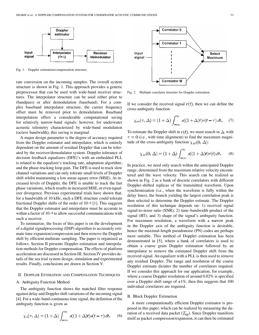
Fig. 2. Multiple correlator structure for Doppler estimation.
If we consider the received signal
cross-ambiguity function
, then we can define the
(7)
To estimate the Doppler shift in
, with
(i.e., with time alignment) to find the maximum magni-
, we must search in
tude of the cross-ambiguity function
:
(8)
In practice, we need only search within the anticipated Doppler
range, determined from the maximum relative velocity encoun-
tered and the wave velocity. This search can be realized as
shown in Fig. 2 as a bank of discrete correlators with different
Doppler-shifted replicas of the transmitted waveform. Upon
synchronization (i.e., when the waveform is fully within the
delay lines), the branch yielding the largest correlation peak is
then selected to determine the Doppler estimate. The Doppler
resolution of this technique depends on: 1) received signal
signal-to-noise ratio (SNR); 2) time–bandwidth product of the
signal (BT); and 3) shape of the signal’s ambiguity function.
For maximum resolution, a waveform with a narrow peak
in the Doppler axis of the ambiguity function is desirable,
hence the maximal-length pseudonoise (PN) codes are perhaps
most suitable. This method of Doppler estimation has been
demonstrated in [5], where a bank of correlators is used to
obtain a coarse grain Doppler estimation followed by an
interpolator to remove the estimated Doppler shift from the
received signal. An equalizer with a PLL is then used to remove
any residual Doppler. The range and resolution of the coarse
Doppler estimate dictates the number of correlators required.
If we consider this approach for our application, for example,
where a coarse Doppler resolution of around 0.02% is specified
over a Doppler shift range of ±1%, then this suggests that 100
individual correlators are required.
B. Block Doppler Estimation
A more computationally efficient Doppler estimator is pro-
posed in this paper, which can be realized by measuring the du-
). Since Doppler manifests
ration of a received data packet (
itself as packet compression/expansion, it can then be estimated
�
54
IEEE JOURNAL OF OCEANIC ENGINEERING, VOL. 25, NO. 1, JANUARY 2000
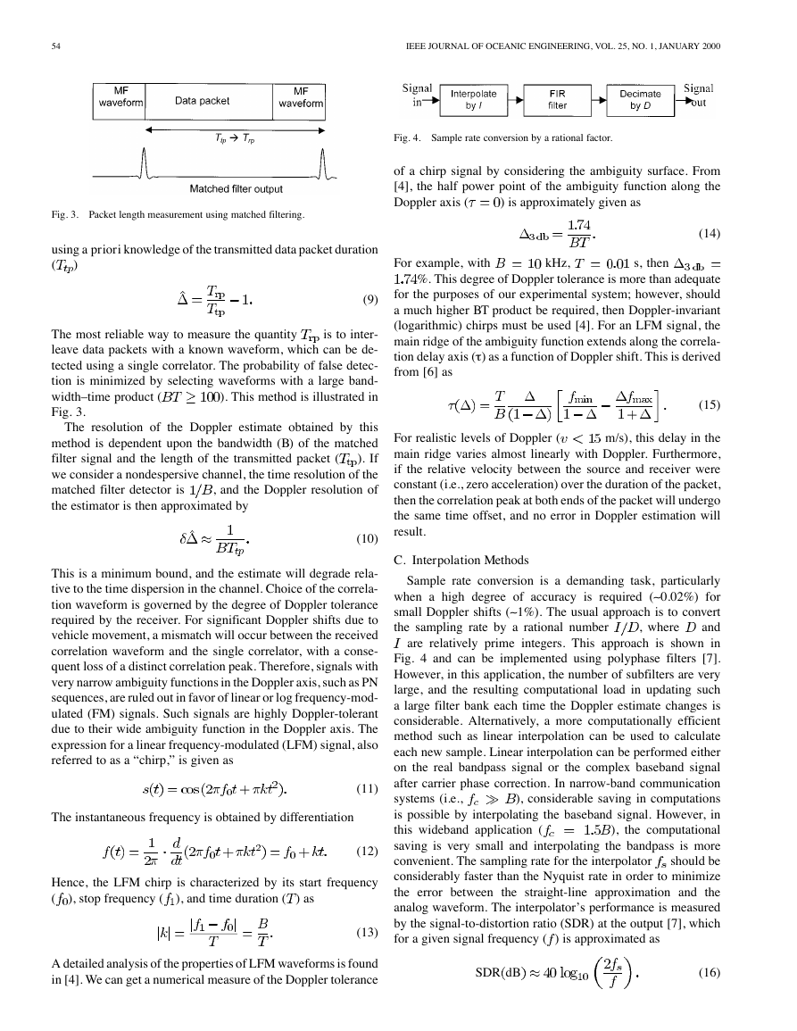
Fig. 3. Packet length measurement using matched filtering.
using a priori knowledge of the transmitted data packet duration
(
)
(9)
is to inter-
The most reliable way to measure the quantity
leave data packets with a known waveform, which can be de-
tected using a single correlator. The probability of false detec-
tion is minimized by selecting waveforms with a large band-
). This method is illustrated in
width–time product (
Fig. 3.
The resolution of the Doppler estimate obtained by this
method is dependent upon the bandwidth (B) of the matched
). If
filter signal and the length of the transmitted packet (
we consider a nondespersive channel, the time resolution of the
, and the Doppler resolution of
matched filter detector is
the estimator is then approximated by
(10)
This is a minimum bound, and the estimate will degrade rela-
tive to the time dispersion in the channel. Choice of the correla-
tion waveform is governed by the degree of Doppler tolerance
required by the receiver. For significant Doppler shifts due to
vehicle movement, a mismatch will occur between the received
correlation waveform and the single correlator, with a conse-
quent loss of a distinct correlation peak. Therefore, signals with
very narrow ambiguity functions in the Doppler axis, such as PN
sequences, are ruled out in favor of linear or log frequency-mod-
ulated (FM) signals. Such signals are highly Doppler-tolerant
due to their wide ambiguity function in the Doppler axis. The
expression for a linear frequency-modulated (LFM) signal, also
referred to as a “chirp,” is given as
The instantaneous frequency is obtained by differentiation
(11)
(12)
Hence, the LFM chirp is characterized by its start frequency
(
), and time duration (
), stop frequency (
) as
(13)
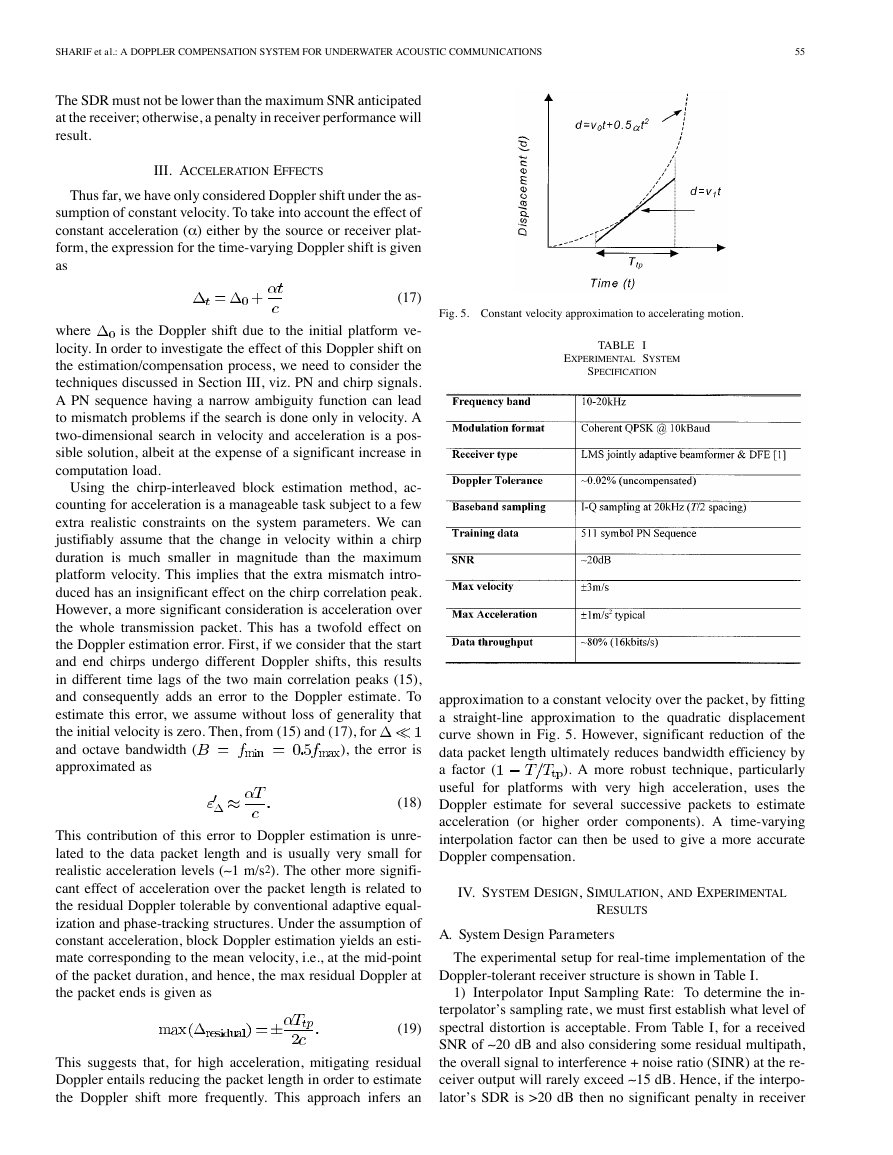
Fig. 4. Sample rate conversion by a rational factor.
of a chirp signal by considering the ambiguity surface. From
[4], the half power point of the ambiguity function along the
Doppler axis (
) is approximately given as
(14)
For example, with
kHz,
s, then
%. This degree of Doppler tolerance is more than adequate
for the purposes of our experimental system; however, should
a much higher BT product be required, then Doppler-invariant
(logarithmic) chirps must be used [4]. For an LFM signal, the
main ridge of the ambiguity function extends along the correla-
tion delay axis (t ) as a function of Doppler shift. This is derived
from [6] as
(15)
m/s), this delay in the
For realistic levels of Doppler (
main ridge varies almost linearly with Doppler. Furthermore,
if the relative velocity between the source and receiver were
constant (i.e., zero acceleration) over the duration of the packet,
then the correlation peak at both ends of the packet will undergo
the same time offset, and no error in Doppler estimation will
result.
C. Interpolation Methods
, where
Sample rate conversion is a demanding task, particularly
when a high degree of accuracy is required (~ 0.02%) for
small Doppler shifts (~ 1%). The usual approach is to convert
and
the sampling rate by a rational number
are relatively prime integers. This approach is shown in
Fig. 4 and can be implemented using polyphase filters [7].
However, in this application, the number of subfilters are very
large, and the resulting computational load in updating such
a large filter bank each time the Doppler estimate changes is
considerable. Alternatively, a more computationally efficient
method such as linear interpolation can be used to calculate
each new sample. Linear interpolation can be performed either
on the real bandpass signal or the complex baseband signal
after carrier phase correction. In narrow-band communication
), considerable saving in computations
systems (i.e.,
is possible by interpolating the baseband signal. However, in
), the computational
this wideband application (
saving is very small and interpolating the bandpass is more
should be
convenient. The sampling rate for the interpolator
considerably faster than the Nyquist rate in order to minimize
the error between the straight-line approximation and the
analog waveform. The interpolator’s performance is measured
by the signal-to-distortion ratio (SDR) at the output [7], which
for a given signal frequency ( ) is approximated as
A detailed analysis of the properties of LFM waveforms is found
in [4]. We can get a numerical measure of the Doppler tolerance
SDR dB
(16)
�
SHARIF et al.: A DOPPLER COMPENSATION SYSTEM FOR UNDERWATER ACOUSTIC COMMUNICATIONS
55
The SDR must not be lower than the maximum SNR anticipated
at the receiver; otherwise, a penalty in receiver performance will
result.
III. ACCELERATION EFFECTS
Thus far, we have only considered Doppler shift under the as-
sumption of constant velocity. To take into account the effect of
constant acceleration (a ) either by the source or receiver plat-
form, the expression for the time-varying Doppler shift is given
as
(17)
Fig. 5. Constant velocity approximation to accelerating motion.
is the Doppler shift due to the initial platform ve-
where
locity. In order to investigate the effect of this Doppler shift on
the estimation/compensation process, we need to consider the
techniques discussed in Section III, viz. PN and chirp signals.
A PN sequence having a narrow ambiguity function can lead
to mismatch problems if the search is done only in velocity. A
two-dimensional search in velocity and acceleration is a pos-
sible solution, albeit at the expense of a significant increase in
computation load.
Using the chirp-interleaved block estimation method, ac-
counting for acceleration is a manageable task subject to a few
extra realistic constraints on the system parameters. We can
justifiably assume that the change in velocity within a chirp
duration is much smaller in magnitude than the maximum
platform velocity. This implies that the extra mismatch intro-
duced has an insignificant effect on the chirp correlation peak.
However, a more significant consideration is acceleration over
the whole transmission packet. This has a twofold effect on
the Doppler estimation error. First, if we consider that the start
and end chirps undergo different Doppler shifts, this results
in different time lags of the two main correlation peaks (15),
and consequently adds an error to the Doppler estimate. To
estimate this error, we assume without loss of generality that
the initial velocity is zero. Then, from (15) and (17), for
and octave bandwidth (
approximated as
), the error is
(18)
This contribution of this error to Doppler estimation is unre-
lated to the data packet length and is usually very small for
realistic acceleration levels (~ 1 m/s2). The other more signifi-
cant effect of acceleration over the packet length is related to
the residual Doppler tolerable by conventional adaptive equal-
ization and phase-tracking structures. Under the assumption of
constant acceleration, block Doppler estimation yields an esti-
mate corresponding to the mean velocity, i.e., at the mid-point
of the packet duration, and hence, the max residual Doppler at
the packet ends is given as
This suggests that, for high acceleration, mitigating residual
Doppler entails reducing the packet length in order to estimate
the Doppler shift more frequently. This approach infers an
(19)
TABLE I
EXPERIMENTAL SYSTEM
SPECIFICATION
approximation to a constant velocity over the packet, by fitting
a straight-line approximation to the quadratic displacement
curve shown in Fig. 5. However, significant reduction of the
data packet length ultimately reduces bandwidth efficiency by
). A more robust technique, particularly
a factor (
useful for platforms with very high acceleration, uses the
Doppler estimate for several successive packets to estimate
acceleration (or higher order components). A time-varying
interpolation factor can then be used to give a more accurate
Doppler compensation.
IV. SYSTEM DESIGN, SIMULATION, AND EXPERIMENTAL
A. System Design Parameters
RESULTS
The experimental setup for real-time implementation of the
Doppler-tolerant receiver structure is shown in Table I.
1) Interpolator Input Sampling Rate: To determine the in-
terpolator’s sampling rate, we must first establish what level of
spectral distortion is acceptable. From Table I, for a received
SNR of ~ 20 dB and also considering some residual multipath,
the overall signal to interference + noise ratio (SINR) at the re-
ceiver output will rarely exceed ~ 15 dB. Hence, if the interpo-
lator’s SDR is >20 dB then no significant penalty in receiver
�
56
IEEE JOURNAL OF OCEANIC ENGINEERING, VOL. 25, NO. 1, JANUARY 2000
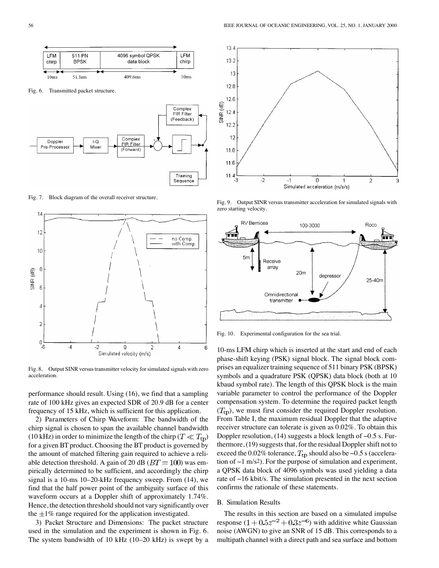
Fig. 6. Transmitted packet structure.
Fig. 7. Block diagram of the overall receiver structure.
Fig. 9. Output SINR versus transmitter acceleration for simulated signals with
zero starting velocity.
Fig. 8. Output SINR versus transmitter velocity for simulated signals with zero
acceleration.
performance should result. Using (16), we find that a sampling
rate of 100 kHz gives an expected SDR of 20.9 dB for a center
frequency of 15 kHz, which is sufficient for this application.
2) Parameters of Chirp Waveform: The bandwidth of the
chirp signal is chosen to span the available channel bandwidth
)
(10 kHz) in order to minimize the length of the chirp (
for a given BT product. Choosing the BT product is governed by
the amount of matched filtering gain required to achieve a reli-
) was em-
able detection threshold. A gain of 20 dB (
pirically determined to be sufficient, and accordingly the chirp
signal is a 10-ms 10–20-kHz frequency sweep. From (14), we
find that the half power point of the ambiguity surface of this
waveform occurs at a Doppler shift of approximately 1.74%.
Hence, the detection threshold should not vary significantly over
the
1% range required for the application investigated.
3) Packet Structure and Dimensions: The packet structure
used in the simulation and the experiment is shown in Fig. 6.
The system bandwidth of 10 kHz (10–20 kHz) is swept by a
Fig. 10. Experimental configuration for the sea trial.
10-ms LFM chirp which is inserted at the start and end of each
phase-shift keying (PSK) signal block. The signal block com-
prises an equalizer training sequence of 511 binary PSK (BPSK)
symbols and a quadrature PSK (QPSK) data block (both at 10
kbaud symbol rate). The length of this QPSK block is the main
variable parameter to control the performance of the Doppler
compensation system. To determine the required packet length
), we must first consider the required Doppler resolution.
(
From Table I, the maximum residual Doppler that the adaptive
receiver structure can tolerate is given as 0.02%. To obtain this
Doppler resolution, (14) suggests a block length of ~ 0.5 s. Fur-
thermore, (19) suggests that, for the residual Doppler shift not to
should also be ~ 0.5 s (accelera-
exceed the 0.02% tolerance,
tion of ~ 1 m/s2). For the purpose of simulation and experiment,
a QPSK data block of 4096 symbols was used yielding a data
rate of ~ 16 kbit/s. The simulation presented in the next section
confirms the rationale of these statements.
B. Simulation Results
The results in this section are based on a simulated impulse
) with additive white Gaussian
response (
noise (AWGN) to give an SNR of 15 dB. This corresponds to a
multipath channel with a direct path and sea surface and bottom
�
SHARIF et al.: A DOPPLER COMPENSATION SYSTEM FOR UNDERWATER ACOUSTIC COMMUNICATIONS
57
(a)
(c)
(b)
(d)
Fig. 11. Graphical output for +1.6-m/s velocity and 200-m range. (a) MSE curve during training. (b) Output envelope during data. (c) I–Q plot. (d) Channel
impulse response.
reflections. Transmitter velocity and acceleration are simulated
by interpolating the source signals by a constant or linearly
ramped factor, respectively. The receiver structure, as shown in
Fig. 7, consists of the Doppler preprocessor of Fig. 1, an in-
phase-quadrature (I-Q) mixer, and a single-element DFE struc-
ture with 20 forward and feedback FIR taps (T/2 fractionally
spaced) and LMS adaptation (m = 0.001) [8]. Fig. 8 shows a plot
(MSE)) of the adaptive receiver
of the output SINR (
versus transmitter velocity, both with and without the Doppler
preprocessor system. For zero velocity, both receivers achieve a
satisfactory convergence with ~ 13-dB SINR, a level that would
allow near error-free QPSK transmission. However, as the ve-
locity increases, the MSE of the uncompensated receiver rapidly
increases to an unacceptable level as the implicit synchroniza-
tion of the equalizer fails. In fact, it requires a velocity of only
0.5 m/s to cause a significant increase in bit errors. In contrast,
the figure shows that the receiver incorporating the Doppler pre-
processor maintains near constant performance over the range
6 m/s. It should be noted that a threshold could
of velocity of
be used by the Doppler preprocessor, so that resampling is only
performed if the estimated Doppler shift were above the level
tolerated by the proceeding DFE structure (~ 10- 4 for our appli-
cation).
Fig. 9 shows the performance of the Doppler compensated
receiver versus acceleration, with the starting velocity fixed at
zero. There is only a small degradation (SINR drop of - 1.5 dB)
3 m/s2. If a nonzero
in receiver performance over the range of
starting velocity is chosen, then the performance curve is given
by the superposition of Fig. 9 upon the corresponding velocity in
Fig. 8. These simulation results verify that the design parameters
chosen in (
m/s and
a =±1 m/s2.
) would meet the specification of
C. Experimental Results
The Doppler estimation and compensation scheme presented
in this paper was tested during experimental trials in the North
Sea conducted in July 1998. Fig. 10 shows the experimental
configuration used. The receiver structure was identical to that
simulated above. However, in this case, a six-element rigid re-
ceiving array with l
spacing (15-kHz center frequency) was
used followed by a bank of six tapped delay lines to form a
wide-band adaptive beamformer [1]. The grating lobes effect
resulting from l
spacing is circumvented by the directionality
of the array transducers ( 45 ). In this case, Doppler estima-
tion was performed on one element only, and the same value
was used to compensate the signal from each element. This is
a successful approach provided that array spacing is relatively
small (~
), otherwise separate estimation on each element may
be required for large spatially-diverse arrays.
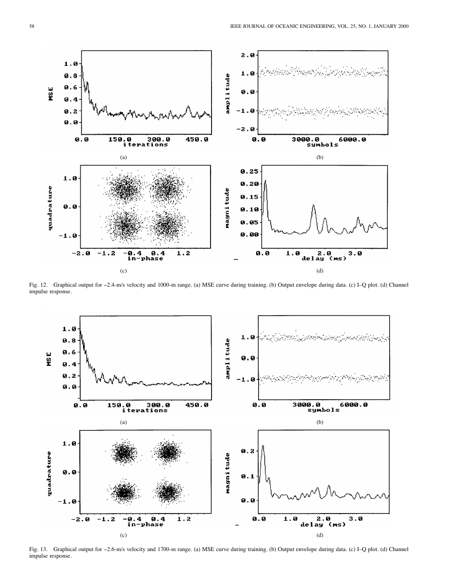
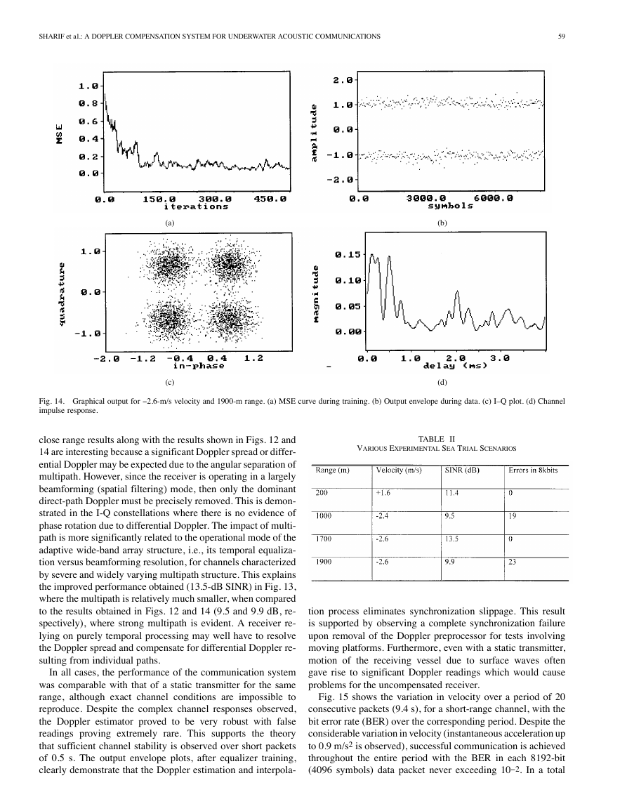
Figs. 11–14 show the output of the receiver system for various
scenarios summarized in Table II. Each plot shows the conver-
gence curve (MSE) during the training phase, the output enve-
lope throughout the 4096-symbol, I-Q constellation and channel
impulse response derived from the chirp correlation. In all cases,
the velocity stated is from the Doppler estimator, which has a
greater accuracy than the vessel’s speed log. Fig. 11 shows a
close range run with the transmitter moving toward the receiver,
demonstrating error-free transmission (11.4-dB SINR). These
l
�
58
IEEE JOURNAL OF OCEANIC ENGINEERING, VOL. 25, NO. 1, JANUARY 2000
(a)
(c)
(b)
(d)
Fig. 12. Graphical output for - 2.4-m/s velocity and 1000-m range. (a) MSE curve during training. (b) Output envelope during data. (c) I–Q plot. (d) Channel
impulse response.
(a)
(c)
(b)
(d)
Fig. 13. Graphical output for - 2.6-m/s velocity and 1700-m range. (a) MSE curve during training. (b) Output envelope during data. (c) I–Q plot. (d) Channel
impulse response.
�
SHARIF et al.: A DOPPLER COMPENSATION SYSTEM FOR UNDERWATER ACOUSTIC COMMUNICATIONS
59
(a)
(c)
(b)
(d)
Fig. 14. Graphical output for - 2.6-m/s velocity and 1900-m range. (a) MSE curve during training. (b) Output envelope during data. (c) I–Q plot. (d) Channel
impulse response.
close range results along with the results shown in Figs. 12 and
14 are interesting because a significant Doppler spread or differ-
ential Doppler may be expected due to the angular separation of
multipath. However, since the receiver is operating in a largely
beamforming (spatial filtering) mode, then only the dominant
direct-path Doppler must be precisely removed. This is demon-
strated in the I-Q constellations where there is no evidence of
phase rotation due to differential Doppler. The impact of multi-
path is more significantly related to the operational mode of the
adaptive wide-band array structure, i.e., its temporal equaliza-
tion versus beamforming resolution, for channels characterized
by severe and widely varying multipath structure. This explains
the improved performance obtained (13.5-dB SINR) in Fig. 13,
where the multipath is relatively much smaller, when compared
to the results obtained in Figs. 12 and 14 (9.5 and 9.9 dB, re-
spectively), where strong multipath is evident. A receiver re-
lying on purely temporal processing may well have to resolve
the Doppler spread and compensate for differential Doppler re-
sulting from individual paths.
In all cases, the performance of the communication system
was comparable with that of a static transmitter for the same
range, although exact channel conditions are impossible to
reproduce. Despite the complex channel responses observed,
the Doppler estimator proved to be very robust with false
readings proving extremely rare. This supports the theory
that sufficient channel stability is observed over short packets
of 0.5 s. The output envelope plots, after equalizer training,
clearly demonstrate that the Doppler estimation and interpola-
VARIOUS EXPERIMENTAL SEA TRIAL SCENARIOS
TABLE II
tion process eliminates synchronization slippage. This result
is supported by observing a complete synchronization failure
upon removal of the Doppler preprocessor for tests involving
moving platforms. Furthermore, even with a static transmitter,
motion of the receiving vessel due to surface waves often
gave rise to significant Doppler readings which would cause
problems for the uncompensated receiver.
Fig. 15 shows the variation in velocity over a period of 20
consecutive packets (9.4 s), for a short-range channel, with the
bit error rate (BER) over the corresponding period. Despite the
considerable variation in velocity (instantaneous acceleration up
to 0.9 m/s2 is observed), successful communication is achieved
throughout the entire period with the BER in each 8192-bit
(4096 symbols) data packet never exceeding 10- 2. In a total
�



 2023年江西萍乡中考道德与法治真题及答案.doc
 2012年重庆南川中考生物真题及答案.doc
 2013年江西师范大学地理学综合及文艺理论基础考研真题.doc
 2020年四川甘孜小升初语文真题及答案I卷.doc
 2020年注册岩土工程师专业基础考试真题及答案.doc
 2023-2024学年福建省厦门市九年级上学期数学月考试题及答案.doc
 2021-2022学年辽宁省沈阳市大东区九年级上学期语文期末试题及答案.doc
 2022-2023学年北京东城区初三第一学期物理期末试卷及答案.doc
 2018上半年江西教师资格初中地理学科知识与教学能力真题及答案.doc
 2012年河北国家公务员申论考试真题及答案-省级.doc
 2020-2021学年江苏省扬州市江都区邵樊片九年级上学期数学第一次质量检测试题及答案.doc
 2022下半年黑龙江教师资格证中学综合素质真题及答案.doc