logo资料库

OV426_BGA_DS_2.11_OVT.pdf

第1页 / 共75页
第2页 / 共75页
第3页 / 共75页
第4页 / 共75页
第5页 / 共75页
第6页 / 共75页
第7页 / 共75页
第8页 / 共75页
资料共75页,剩余部分请下载后查看
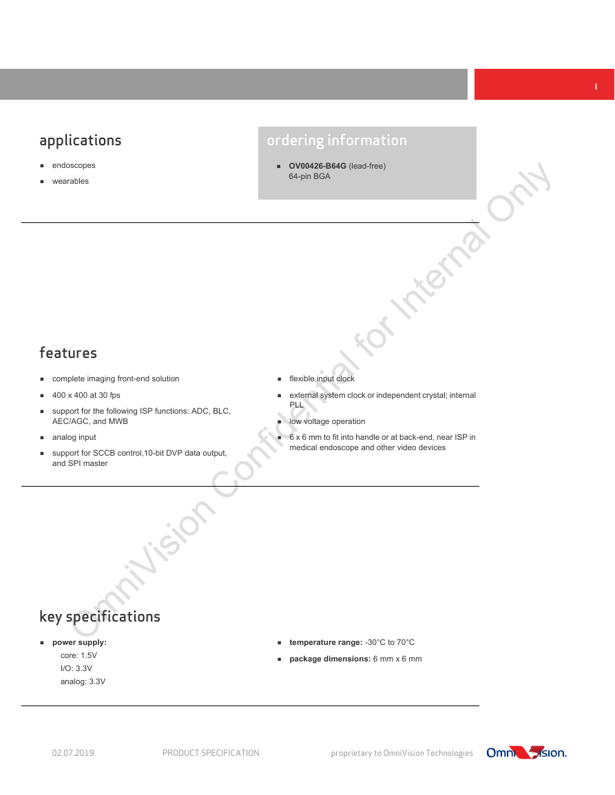
applications
features
key specifications
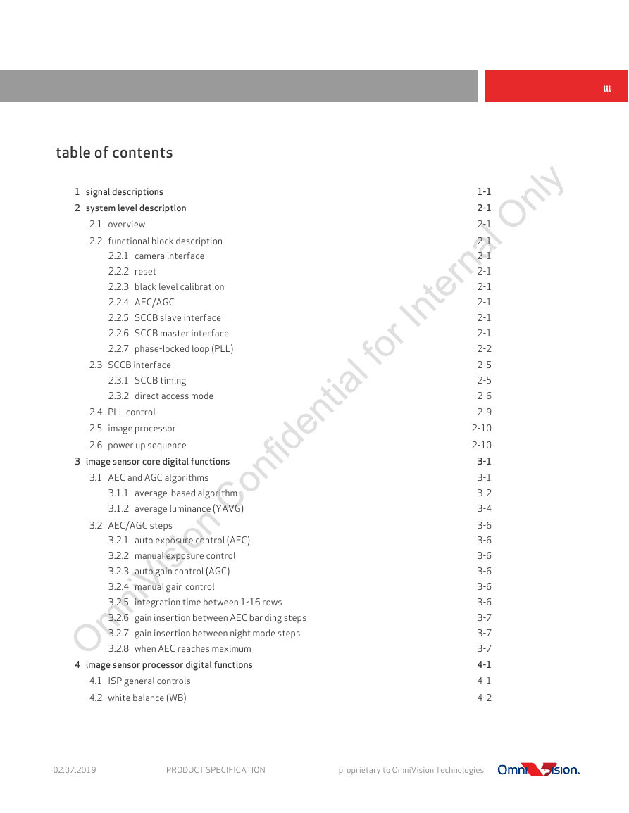
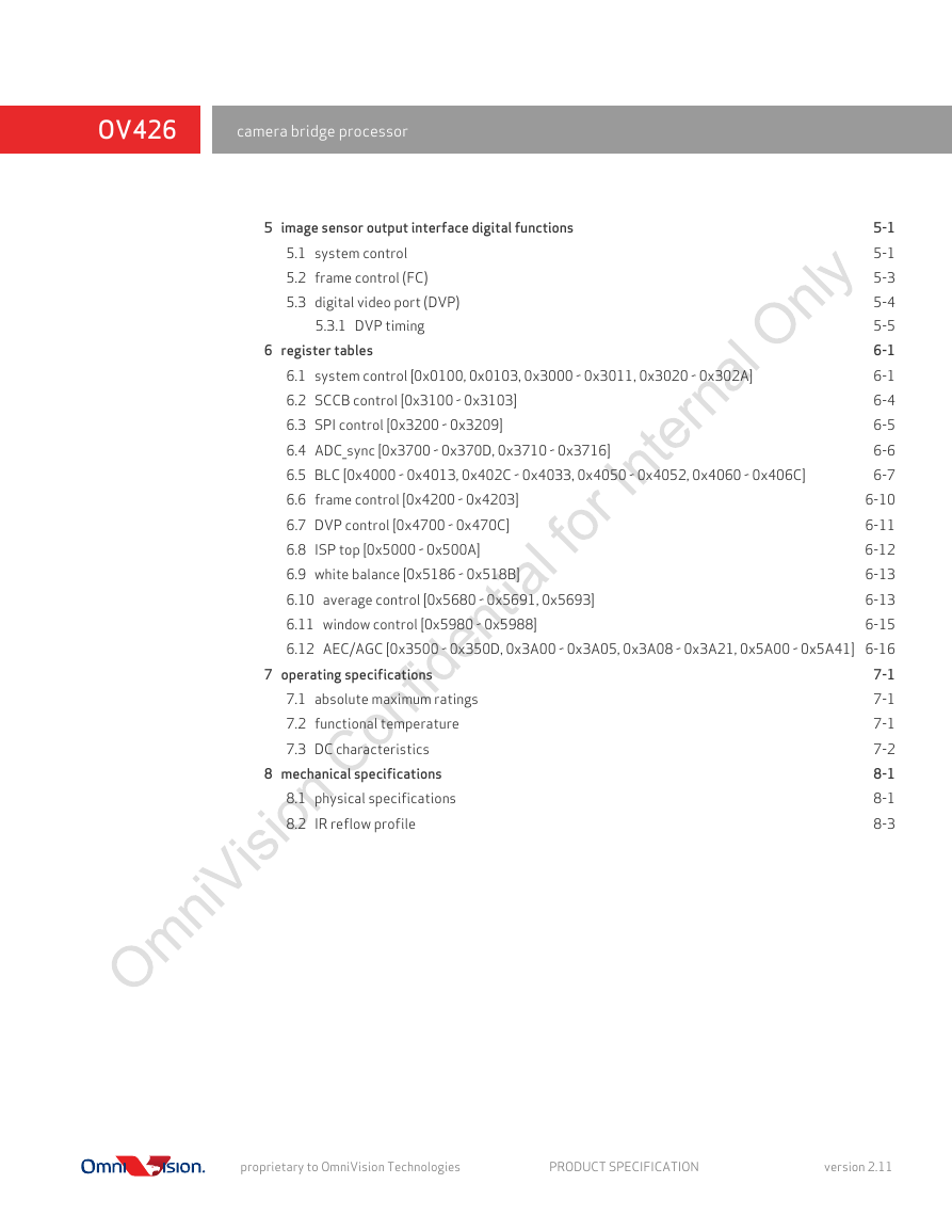
table of contents
list of figures
list of tables
1 signal descriptions
figure 1-1 pin diagram
table 1-1 signal descriptions (sheet 1 of 3)
table 1-2 pad symbol and equivalent circuit (sheet 1 of 2)
2 system level description
2.1 overview
figure 2-1 OV426 medical system block diagram
2.2 functional block description
2.2.1 camera interface
2.2.2 reset
2.2.3 black level calibration
2.2.4 AEC/AGC
2.2.5 SCCB slave interface
2.2.6 SCCB master interface
2.2.7 phase-locked loop (PLL)
figure 2-2 OV426 functional block diagram
figure 2-3 OV426 reference schematic
figure 2-4 OV426 160Kpixel (400 x 400) diagram
2.3 SCCB interface
2.3.1 SCCB timing
figure 2-5 SCCB interface timing
table 2-1 SCCB interface timing specifications
2.3.2 direct access mode
figure 2-6 message type
figure 2-7 SCCB single read from random location
figure 2-8 SCCB single read from current location
figure 2-9 SCCB sequential read from random location
figure 2-10 SCCB sequential read from current location
figure 2-11 SCCB single write to random location
figure 2-12 SCCB sequential write to random location
2.4 PLL control
figure 2-13 PLL control diagram
table 2-2 PLL control registers
2.5 image processor
figure 2-14 image processor block diagram
2.6 power up sequence
table 2-3 power up sequence timing constraints
figure 2-15 power up sequence
3 image sensor core digital functions
3.1 AEC and AGC algorithms
table 3-1 AEC/AGC control function registers
3.1.1 average-based algorithm
figure 3-1 AEC/AGC auto speed (step) mode diagram
figure 3-2 AEC/AGC manual speed (step) mode diagram
table 3-2 average based control function registers (sheet 1 of 2)
3.1.2 average luminance (YAVG)
figure 3-3 average-based window definition
table 3-3 average luminance control function registers (sheet 1 of 2)
3.2 AEC/AGC steps
3.2.1 auto exposure control (AEC)
3.2.2 manual exposure control
3.2.3 auto gain control (AGC)
3.2.4 manual gain control
3.2.5 integration time between 1~16 rows
3.2.6 gain insertion between AEC banding steps
3.2.7 gain insertion between night mode steps
3.2.8 when AEC reaches maximum
4 image sensor processor digital functions
4.1 ISP general controls
table 4-1 ISP general control registers
4.2 white balance (WB)
table 4-2 WB control registers
5 image sensor output interface digital functions
5.1 system control
table 5-1 system control registers (sheet 1 of 3)
5.2 frame control (FC)
table 5-2 frame control registers
5.3 digital video port (DVP)
table 5-3 DVP registers
5.3.1 DVP timing
figure 5-1 DVP timing diagram
table 5-4 DVP timing specifications for OV6946
table 5-5 DVP timing specifications for OV6948
figure 5-2 DVP setup/hold time diagram
table 5-6 DVP setup/hold time
6 register tables
6.1 system control [0x0100, 0x0103, 0x3000 ~ 0x3011, 0x3020 ~ 0x302A]
table 6-1 system control registers (sheet 1 of 3)
6.2 SCCB control [0x3100 ~ 0x3103]
table 6-2 SCCB control registers
6.3 SPI control [0x3200 ~ 0x3209]
table 6-3 SPI registers
6.4 ADC_sync [0x3700 ~ 0x370D, 0x3710 ~ 0x3716]
table 6-4 ADC_sync registers (sheet 1 of 2)
6.5 BLC [0x4000 ~ 0x4013, 0x402C ~ 0x4033, 0x4050 ~ 0x4052, 0x4060 ~ 0x406C]
table 6-5 BLC control registers (sheet 1 of 4)
6.6 frame control [0x4200 ~ 0x4203]
table 6-6 frame control registers
6.7 DVP control [0x4700 ~ 0x470C]
table 6-7 DVP registers (sheet 1 of 2)
6.8 ISP top [0x5000 ~ 0x500A]
table 6-8 ISP top registers (sheet 1 of 2)
6.9 white balance [0x5186 ~ 0x518B]
table 6-9 WB control registers
6.10 average control [0x5680 ~ 0x5691, 0x5693]
table 6-10 average registers (sheet 1 of 2)
6.11 window control [0x5980 ~ 0x5988]
table 6-11 window registers
6.12 AEC/AGC [0x3500 ~ 0x350D, 0x3A00 ~ 0x3A05, 0x3A08 ~ 0x3A21, 0x5A00 ~ 0x5A41]
table 6-12 AEC/AGC registers (sheet 1 of 4)
7 operating specifications
7.1 absolute maximum ratings
table 7-1 absolute maximum ratings
7.2 functional temperature
table 7-2 functional temperature
7.3 DC characteristics
table 7-3 DC characteristics
8 mechanical specifications
8.1 physical specifications
figure 8-1 package specifications
table 8-1 package dimensions (sheet 1 of 2)
8.2 IR reflow profile
figure 8-2 IR reflow profile suggestion (lead free solder)
table 8-2 reflow conditions
revision history
datasheet PRODUCT SPECIFICATION camera bridge processor 6 2 4 V O
OV426 camera bridge processor 00Copyright © 2019 OmniVision Technologies, Inc. All rights reserved. This document is provided “as is” with no warranties whatsoever, including any warranty of merchantability, non-infringement, fitness for any particular purpose, or any warranty otherwise arising out of any proposal, specification, or sample. OmniVision Technologies, Inc. and all its affiliates disclaim all liability, including liability for infringement of any proprietary rights, relating to the use of information in this document. No license, expressed or implied, by estoppel or otherwise, to any intellectual property rights is granted herein. The information contained in this document is considered proprietary to OmniVision Technologies, Inc. and all its affiliates. This information may be distributed to individuals or organizations authorized by OmniVision Technologies, Inc. to receive said information. Individuals and/or organizations are not allowed to re-distribute said information. Trademark Information All other trademarks used herein are the property of their respective owners. OmniVision and the OmniVision logo are registered trademarks of OmniVision Technologies, Inc. camera bridge processor datasheet (BGA) PRODUCT SPECIFICATION version 2.11 february 2019 To learn more about OmniVision Technologies, visit www.ovt.com.
i 00applications endoscopes wearables 00features complete imaging front-end solution 400 x 400 at 30 fps support for the following ISP functions: ADC, BLC, AEC/AGC, and MWB analog input support for SCCB control,10-bit DVP data output, and SPI master ordering information OV00426-B64G (lead-free) 64-pin BGA external system clock or independent crystal; internal low voltage operation 6 x 6 mm to fit into handle or at back-end, near ISP in medical endoscope and other video devices flexible input clock PLL temperature range: -30°C to 70°C package dimensions: 6 mm x 6 mm 00key specifications power supply: core: 1.5V I/O: 3.3V analog: 3.3V 02.07.2019 PRODUCT SPECIFICATION proprietary to OmniVision Technologies
OV426 camera bridge processor proprietary to OmniVision Technologies PRODUCT SPECIFICATION version 2.11
00table of contents iii 2.3 SCCB interface 1 signal descriptions 2 system level description 2.1 overview 2.2 functional block description 2.3.1 SCCB timing 2.3.2 direct access mode 2.2.1 camera interface 2.2.2 reset 2.2.3 black level calibration 2.2.4 AEC/AGC 2.2.5 SCCB slave interface 2.2.6 SCCB master interface 2.2.7 phase-locked loop (PLL) 3.1.1 average-based algorithm 3.1.2 average luminance (YAVG) 3.2.1 auto exposure control (AEC) 3.2.2 manual exposure control 3.2.3 auto gain control (AGC) 3.2.4 manual gain control 3.2.5 integration time between 1~16 rows 3.2.6 gain insertion between AEC banding steps 3.2.7 gain insertion between night mode steps 3.2.8 when AEC reaches maximum 4 image sensor processor digital functions 1-1 2-1 2-1 2-1 2-1 2-1 2-1 2-1 2-1 2-1 2-2 2-5 2-5 2-6 2-9 2-10 2-10 3-1 3-1 3-2 3-4 3-6 3-6 3-6 3-6 3-6 3-6 3-7 3-7 3-7 4-1 4-1 4-2 2.4 PLL control 2.5 image processor 2.6 power up sequence 3 image sensor core digital functions 3.1 AEC and AGC algorithms 3.2 AEC/AGC steps 4.1 ISP general controls 4.2 white balance (WB) 02.07.2019 PRODUCT SPECIFICATION proprietary to OmniVision Technologies
OV426 camera bridge processor 5 image sensor output interface digital functions 5.1 system control 5.2 frame control (FC) 5.3 digital video port (DVP) 5.3.1 DVP timing 5-1 5-1 5-3 5-4 5-5 6-1 6-1 6.1 system control [0x0100, 0x0103, 0x3000 ~ 0x3011, 0x3020 ~ 0x302A] 6-4 6.2 SCCB control [0x3100 ~ 0x3103] 6-5 6.3 SPI control [0x3200 ~ 0x3209] 6-6 6.4 ADC_sync [0x3700 ~ 0x370D, 0x3710 ~ 0x3716] 6-7 6.5 BLC [0x4000 ~ 0x4013, 0x402C ~ 0x4033, 0x4050 ~ 0x4052, 0x4060 ~ 0x406C] 6-10 6.6 frame control [0x4200 ~ 0x4203] 6-11 6.7 DVP control [0x4700 ~ 0x470C] 6-12 6.8 ISP top [0x5000 ~ 0x500A] 6-13 6.9 white balance [0x5186 ~ 0x518B] 6-13 6.10 average control [0x5680 ~ 0x5691, 0x5693] 6.11 window control [0x5980 ~ 0x5988] 6-15 6.12 AEC/AGC [0x3500 ~ 0x350D, 0x3A00 ~ 0x3A05, 0x3A08 ~ 0x3A21, 0x5A00 ~ 0x5A41] 6-16 7-1 7-1 7-1 7-2 8-1 8-1 8-3 7.1 absolute maximum ratings 7.2 functional temperature 7.3 DC characteristics 6 register tables 7 operating specifications 8 mechanical specifications 8.1 physical specifications 8.2 IR reflow profile proprietary to OmniVision Technologies PRODUCT SPECIFICATION version 2.11
00list of figures v figure 1-1 pin diagram figure 2-1 OV426 medical system block diagram figure 2-2 OV426 functional block diagram figure 2-3 OV426 reference schematic figure 2-4 OV426 160Kpixel (400 x 400) diagram figure 2-5 SCCB interface timing figure 2-6 message type figure 2-7 SCCB single read from random location figure 2-8 SCCB single read from current location figure 2-9 SCCB sequential read from random location figure 2-10 SCCB sequential read from current location figure 2-11 SCCB single write to random location figure 2-12 SCCB sequential write to random location figure 2-13 PLL control diagram figure 2-14 image processor block diagram figure 2-15 power up sequence figure 3-1 figure 3-2 figure 3-3 figure 5-1 figure 5-2 figure 8-1 figure 8-2 1-1 2-1 2-2 2-3 2-4 2-5 2-6 2-6 2-7 2-7 2-8 2-8 2-8 2-9 2-10 2-11 3-2 3-3 3-4 5-5 5-6 8-1 8-3 AEC/AGC auto speed (step) mode diagram AEC/AGC manual speed (step) mode diagram average-based window definition DVP timing diagram DVP setup/hold time diagram package specifications IR reflow profile suggestion (lead free solder) 02.07.2019 PRODUCT SPECIFICATION proprietary to OmniVision Technologies
OV426 camera bridge processor proprietary to OmniVision Technologies PRODUCT SPECIFICATION version 2.11
分享到:
收藏