(1/71)
001-02 / 20030309 / e148.fm
EI, EE, EER, ETD, PQ, LP, RM, EPC Series
Ferrite
For Switching Power Supplies
Technical Data
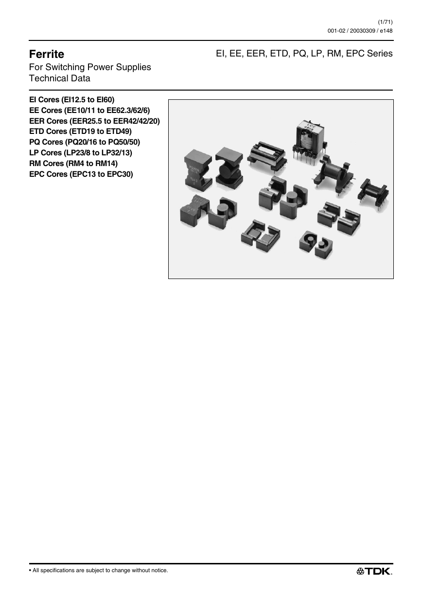
EI Cores (EI12.5 to EI60)
EE Cores (EE10/11 to EE62.3/62/6)
EER Cores (EER25.5 to EER42/42/20)
ETD Cores (ETD19 to ETD49)
PQ Cores (PQ20/16 to PQ50/50)
LP Cores (LP23/8 to LP32/13)
RM Cores (RM4 to RM14)
EPC Cores (EPC13 to EPC30)
• All specifications are subject to change without notice.
�
Ferrite
For Switching Power Supplies
Technical Data
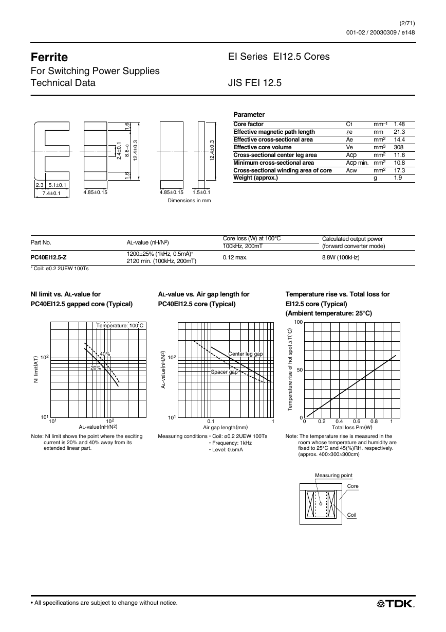
EI Series EI12.5 Cores
JIS FEI 12.5
(2/71)
001-02 / 20030309 / e148.fm
.
1
0
±
4
2
.
.
6
1
0
–
8
8
.
.
6
1
.
3
0
±
4
2
1
.
.
3
0
±
4
2
1
.
2.3 5.1±0.1
7.4±0.1
4.85±0.15
4.85±0.15
1.5±0.1
Dimensions in mm
Parameter
Core factor
Effective magnetic path length
Effective cross-sectional area
Effective core volume
Cross-sectional center leg area
Minimum cross-sectional area
Cross-sectional winding area of core
Weight (approx.)
mm–1 1.48
C1
21.3
mm
e
14.4
mm2
Ae
308
mm3
Ve
Acp
11.6
mm2
Acp min. mm2
10.8
17.3
mm2
Acw
g
1.9
Part No.
PC40EI12.5-Z
∗ Coil: ø0.2 2UEW 100Ts
AL-value (nH/N2)
1200±25% (1kHz, 0.5mA)∗
2120 min. (100kHz, 200mT)
Core loss (W) at 100°C
100kHz, 200mT
0.12 max.
Calculated output power
(forward converter mode)
8.8W (100kHz)
NI limit vs. AL-value for
PC40EI12.5 gapped core (Typical)
AL-value vs. Air gap length for
PC40EI12.5 core (Typical)
Temperature rise vs. Total loss for
EI12.5 core (Typical)
(Ambient temperature: 25°C)
Temperature: 100˚C
102
)
T
A
(
t
i
m
i
l
I
N
40%
20%
101
101
102
AL-value(nH/N2)
Note: NI limit shows the point where the exciting
current is 20% and 40% away from its
extended linear part.
/
)
2
N
H
n
(
e
u
a
v
-
L
A
l
Center leg gap
Spacer gap
100
50
)
C
˚
(
T
∆
t
o
p
s
t
o
h
f
o
e
s
i
r
e
r
u
t
a
r
e
p
m
e
T
0.1
Air gap length(mm)
1
0
0
0.2
102
101
0.4
0.6
Total loss Pm(W)
0.8
1
Measuring conditions Coil: ø0.2 2UEW 100Ts
Frequency: 1kHz
Level: 0.5mA
Note: The temperature rise is measured in the
room whose temperature and humidity are
fixed to 25°C and 45(%)RH. respectively.
(approx. 400×300×300cm)
Measuring point
Core
Coil
All specifications are subject to change without notice.
�
Ferrite
For Switching Power Supplies
Technical Data
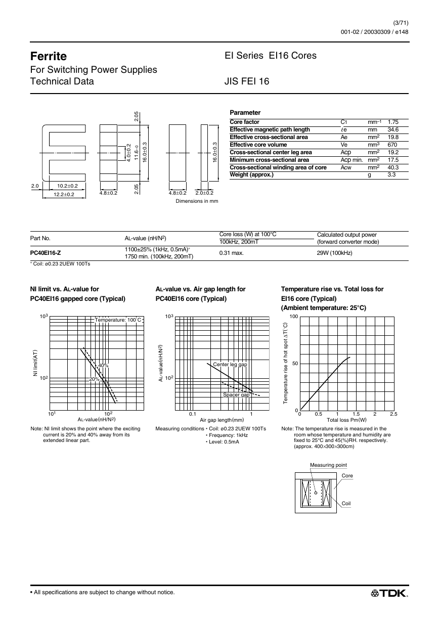
EI Series EI16 Cores
JIS FEI 16
(3/71)
001-02 / 20030309 / e148.fm
.
2
0
±
0
4
.
5
0
2
.
0
–
6
1
1
.
5
0
2
.
.
3
0
±
0
6
1
.
2.0
10.2±0.2
12.2±0.2
4.8±0.2
Parameter
Core factor
Effective magnetic path length
Effective cross-sectional area
Effective core volume
Cross-sectional center leg area
Minimum cross-sectional area
Cross-sectional winding area of core
Weight (approx.)
mm–1 1.75
C1
34.6
mm
e
19.8
mm2
Ae
670
mm3
Ve
Acp
19.2
mm2
Acp min. mm2
17.5
40.3
mm2
Acw
g
3.3
.
3
0
±
0
6
1
.
4.8±0.2
2.0±0.2
Dimensions in mm
Part No.
PC40EI16-Z
∗ Coil: ø0.23 2UEW 100Ts
AL-value (nH/N2)
1100±25% (1kHz, 0.5mA)∗
1750 min. (100kHz, 200mT)
Core loss (W) at 100°C
100kHz, 200mT
0.31 max.
Calculated output power
(forward converter mode)
29W (100kHz)
NI limit vs. AL-value for
PC40EI16 gapped core (Typical)
AL-value vs. Air gap length for
PC40EI16 core (Typical)
Temperature rise vs. Total loss for
EI16 core (Typical)
(Ambient temperature: 25°C)
100
50
)
C
˚
(
T
∆
t
o
p
s
t
o
h
f
o
e
s
i
r
e
r
u
t
a
r
e
p
m
e
T
0
0
0.5
1
1.5
Total loss Pm(W)
2
2.5
Note: The temperature rise is measured in the
room whose temperature and humidity are
fixed to 25°C and 45(%)RH. respectively.
(approx. 400×300×300cm)
Measuring point
Core
Coil
103
Temperature: 100˚C
103
)
T
A
(
t
i
m
i
l
I
N
102
40%
20%
/
)
2
N
H
n
(
e
u
a
v
-
L
A
l
102
Center leg gap
Spacer gap
101
102
AL-value(nH/N2)
Note: NI limit shows the point where the exciting
current is 20% and 40% away from its
extended linear part.
0.1
Air gap length(mm)
1
Measuring conditions Coil: ø0.23 2UEW 100Ts
Frequency: 1kHz
Level: 0.5mA
• All specifications are subject to change without notice.
�
Ferrite
For Switching Power Supplies
Technical Data
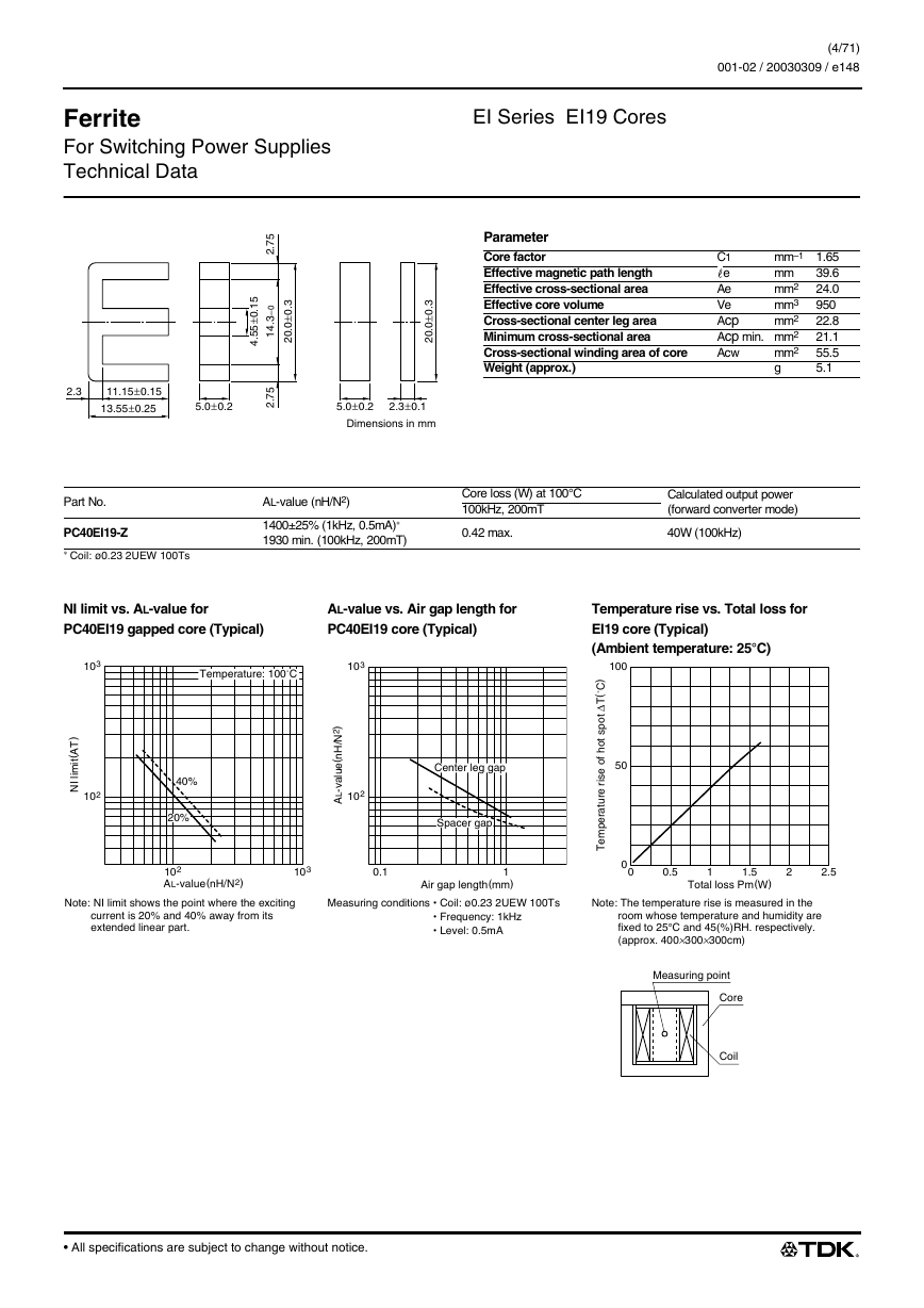
EI Series EI19 Cores
(4/71)
001-02 / 20030309 / e148.fm
.
5
1
0
±
5
5
4
.
5
7
2
.
0
–
3
4
1
.
5
7
2
.
.
3
0
±
0
0
2
.
2.3
11.15±0.15
13.55±0.25
5.0±0.2
.
3
0
±
0
0
2
.
5.0±0.2
2.3±0.1
Dimensions in mm
Parameter
Core factor
Effective magnetic path length
Effective cross-sectional area
Effective core volume
Cross-sectional center leg area
Minimum cross-sectional area
Cross-sectional winding area of core
Weight (approx.)
mm–1 1.65
C1
39.6
mm
e
24.0
mm2
Ae
950
mm3
Ve
Acp
22.8
mm2
Acp min. mm2
21.1
55.5
mm2
Acw
g
5.1
Part No.
PC40EI19-Z
∗ Coil: ø0.23 2UEW 100Ts
AL-value (nH/N2)
1400±25% (1kHz, 0.5mA)∗
1930 min. (100kHz, 200mT)
Core loss (W) at 100°C
100kHz, 200mT
0.42 max.
Calculated output power
(forward converter mode)
40W (100kHz)
NI limit vs. AL-value for
PC40EI19 gapped core (Typical)
AL-value vs. Air gap length for
PC40EI19 core (Typical)
Temperature rise vs. Total loss for
EI19 core (Typical)
(Ambient temperature: 25°C)
103
Temperature: 100˚C
103
)
T
A
(
t
i
m
i
l
I
N
102
40%
20%
/
)
2
N
H
n
(
e
u
a
v
-
L
A
l
102
Center leg gap
Spacer gap
100
50
)
C
˚
(
T
∆
t
o
p
s
t
o
h
f
o
e
s
i
r
e
r
u
t
a
r
e
p
m
e
T
102
AL-value(nH/N2)
103
0.1
1
Air gap length(mm)
0
0
0.5
1
1.5
Total loss Pm(W)
2
2.5
Note: NI limit shows the point where the exciting
current is 20% and 40% away from its
extended linear part.
Measuring conditions Coil: ø0.23 2UEW 100Ts
Frequency: 1kHz
Level: 0.5mA
Note: The temperature rise is measured in the
room whose temperature and humidity are
fixed to 25°C and 45(%)RH. respectively.
(approx. 400×300×300cm)
Measuring point
Core
Coil
• All specifications are subject to change without notice.
�
Ferrite
For Switching Power Supplies
Technical Data
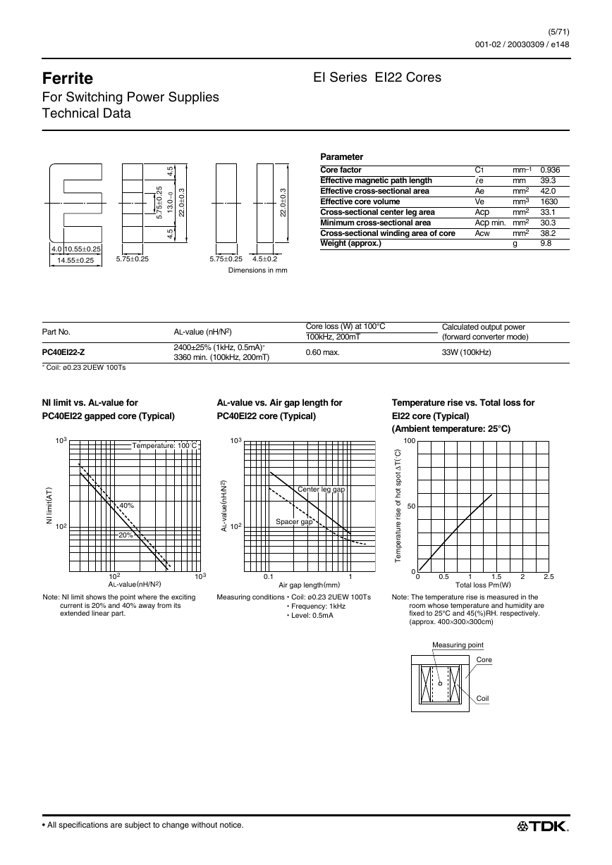
EI Series EI22 Cores
(5/71)
001-02 / 20030309 / e148.fm
.
5
2
0
±
5
7
5
.
5
4
.
0
–
0
3
1
.
.
5
4
.
3
0
±
0
2
2
.
.
3
0
±
0
2
2
.
4.0 10.55±0.25
14.55±0.25
5.75±0.25
5.75±0.25
4.5±0.2
Dimensions in mm
Parameter
Core factor
Effective magnetic path length
Effective cross-sectional area
Effective core volume
Cross-sectional center leg area
Minimum cross-sectional area
Cross-sectional winding area of core
Weight (approx.)
mm–1 0.936
C1
39.3
mm
e
42.0
mm2
Ae
1630
mm3
Ve
Acp
33.1
mm2
Acp min. mm2
30.3
38.2
mm2
Acw
g
9.8
Part No.
PC40EI22-Z
∗ Coil: ø0.23 2UEW 100Ts
AL-value (nH/N2)
2400±25% (1kHz, 0.5mA)∗
3360 min. (100kHz, 200mT)
Core loss (W) at 100°C
100kHz, 200mT
0.60 max.
Calculated output power
(forward converter mode)
33W (100kHz)
NI limit vs. AL-value for
PC40EI22 gapped core (Typical)
AL-value vs. Air gap length for
PC40EI22 core (Typical)
Temperature rise vs. Total loss for
EI22 core (Typical)
(Ambient temperature: 25°C)
100
50
)
C
˚
(
T
∆
t
o
p
s
t
o
h
f
o
e
s
i
r
e
r
u
t
a
r
e
p
m
e
T
0
0
0.5
1
1.5
Total loss Pm(W)
2
2.5
Note: The temperature rise is measured in the
room whose temperature and humidity are
fixed to 25°C and 45(%)RH. respectively.
(approx. 400×300×300cm)
Measuring point
Core
Coil
103
Temperature: 100˚C
103
)
T
A
(
t
i
m
i
l
I
N
102
40%
20%
/
)
2
N
H
n
(
e
u
a
v
-
L
A
l
Center leg gap
102
Spacer gap
102
AL-value(nH/N2)
103
0.1
Air gap length(mm)
1
Note: NI limit shows the point where the exciting
current is 20% and 40% away from its
extended linear part.
Measuring conditions Coil: ø0.23 2UEW 100Ts
Frequency: 1kHz
Level: 0.5mA
• All specifications are subject to change without notice.
�
Ferrite
For Switching Power Supplies
Technical Data
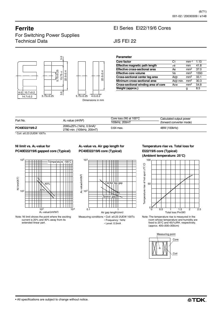
EI Series EI22/19/6 Cores
JIS FEI 22
(6/71)
001-02 / 20030309 / e148.fm
.
5
2
0
±
5
7
5
.
.
0
3
0
–
5
7
5
1
.
.
0
3
.
4
0
±
0
2
2
.
4.0 10.7±0.2
14.7±0.2
5.75±0.25
Parameter
Core factor
Effective magnetic path length
Effective cross-sectional area
Effective core volume
Cross-sectional center leg area
Minimum cross-sectional area
Cross-sectional winding area of core
Weight (approx.)
mm–1 1.13
C1
41.8
mm
e
37.0
mm2
Ae
1550
mm3
Ve
Acp
33.1
mm2
Acp min. mm2
30.3
54.8
mm2
Acw
g
8.5
.
4
0
±
0
2
2
.
5.75±0.25
4.0±0.2
Dimensions in mm
Part No.
PC40EI22/19/6-Z
∗ Coil: ø0.23 2UEW 100Ts
AL-value (nH/N2)
2000±25% (1kHz, 0.5mA)∗
2780 min. (100kHz, 200mT)
Core loss (W) at 100°C
100kHz, 200mT
0.64 max.
Calculated output power
(forward converter mode)
48W (100kHz)
NI limit vs. AL-value for
PC40EI22/19/6 gapped core (Typical)
AL-value vs. Air gap length for
PC40EI22/19/6 core (Typical)
Temperature rise vs. Total loss for
EI22/19/6 core (Typical)
(Ambient temperature: 25°C)
103
Temperature: 100˚C
103
)
T
A
(
t
i
m
i
l
I
N
102
40%
20%
/
)
2
N
H
n
(
e
u
a
v
-
L
A
l
Center leg gap
102
Spacer gap
100
50
)
C
˚
(
T
∆
t
o
p
s
t
o
h
f
o
e
s
i
r
e
r
u
t
a
r
e
p
m
e
T
102
AL-value(nH/N2)
103
0.1
1
Air gap length(mm)
0
0
0.5
1
1.5
Total loss Pm(W)
2
2.5
Note: NI limit shows the point where the exciting
current is 20% and 40% away from its
extended linear part.
Measuring conditions Coil: ø0.23 2UEW 100Ts
Frequency: 1kHz
Level: 0.5mA
Note: The temperature rise is measured in the
room whose temperature and humidity are
fixed to 25°C and 45(%)RH. respectively.
(approx. 400×300×300cm)
Measuring point
Core
Coil
• All specifications are subject to change without notice.
�
Ferrite
For Switching Power Supplies
Technical Data
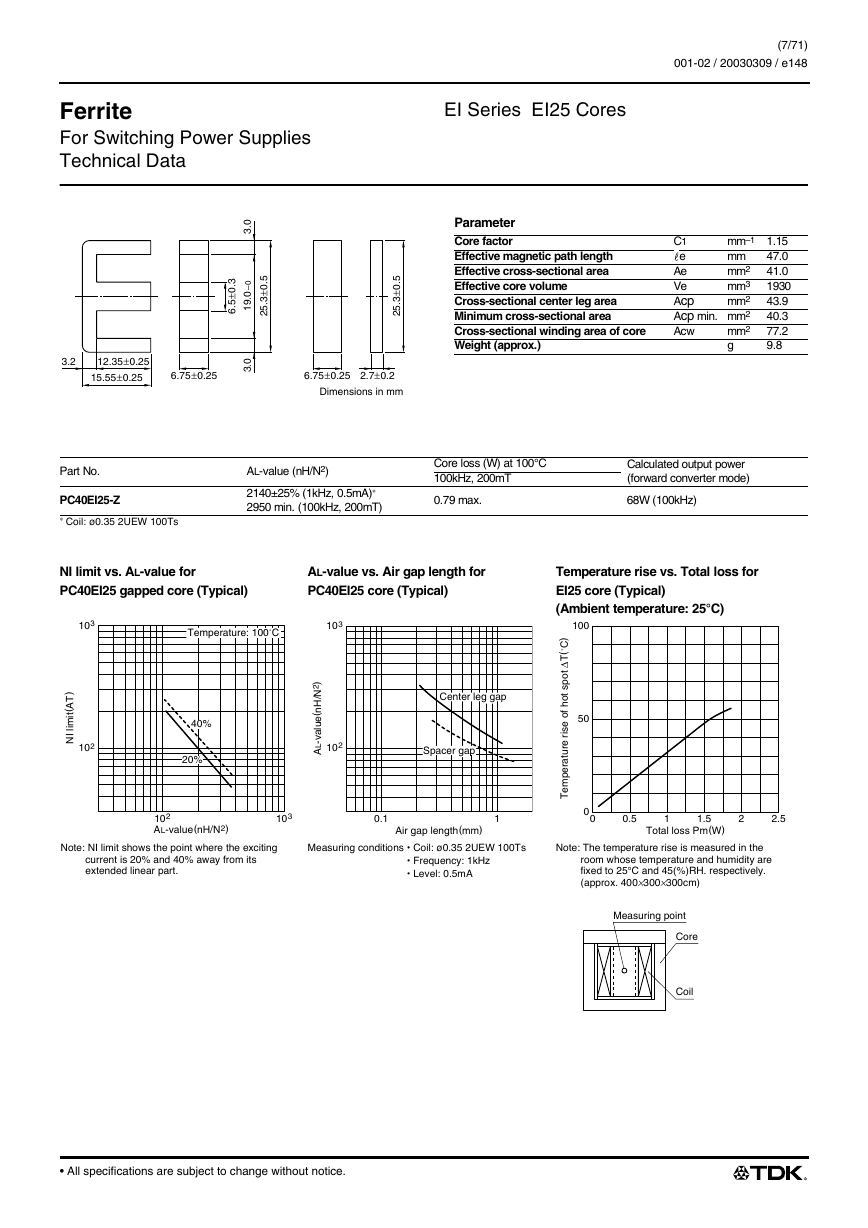
EI Series EI25 Cores
(7/71)
001-02 / 20030309 / e148.fm
.
3
0
±
5
6
.
.
0
3
0
–
0
9
1
.
.
0
3
.
5
0
±
3
5
2
.
3.2
12.35±0.25
15.55±0.25
6.75±0.25
.
5
0
±
3
5
2
.
6.75±0.25
2.7±0.2
Dimensions in mm
Parameter
Core factor
Effective magnetic path length
Effective cross-sectional area
Effective core volume
Cross-sectional center leg area
Minimum cross-sectional area
Cross-sectional winding area of core
Weight (approx.)
mm–1 1.15
C1
47.0
mm
e
41.0
mm2
Ae
1930
mm3
Ve
Acp
43.9
mm2
Acp min. mm2
40.3
77.2
mm2
Acw
g
9.8
Part No.
PC40EI25-Z
∗ Coil: ø0.35 2UEW 100Ts
AL-value (nH/N2)
2140±25% (1kHz, 0.5mA)∗
2950 min. (100kHz, 200mT)
Core loss (W) at 100°C
100kHz, 200mT
0.79 max.
Calculated output power
(forward converter mode)
68W (100kHz)
NI limit vs. AL-value for
PC40EI25 gapped core (Typical)
AL-value vs. Air gap length for
PC40EI25 core (Typical)
Temperature rise vs. Total loss for
EI25 core (Typical)
(Ambient temperature: 25°C)
100
50
)
C
˚
(
T
∆
t
o
p
s
t
o
h
f
o
e
s
i
r
e
r
u
t
a
r
e
p
m
e
T
0
0
0.5
1
1.5
Total loss Pm(W)
2
2.5
Note: The temperature rise is measured in the
room whose temperature and humidity are
fixed to 25°C and 45(%)RH. respectively.
(approx. 400×300×300cm)
Measuring point
Core
Coil
103
Temperature: 100˚C
103
)
T
A
(
t
i
m
i
l
I
N
102
40%
20%
/
)
2
N
H
n
(
e
u
a
v
-
L
A
l
Center leg gap
102
Spacer gap
102
AL-value(nH/N2)
103
0.1
Air gap length(mm)
1
Note: NI limit shows the point where the exciting
current is 20% and 40% away from its
extended linear part.
Measuring conditions Coil: ø0.35 2UEW 100Ts
Frequency: 1kHz
Level: 0.5mA
• All specifications are subject to change without notice.
�
Ferrite
For Switching Power Supplies
Technical Data
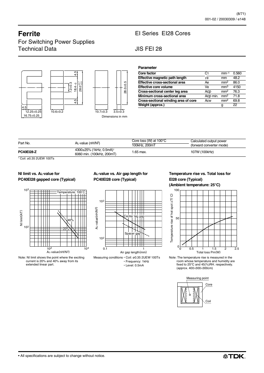
EI Series EI28 Cores
JIS FEI 28
(8/71)
001-02 / 20030309 / e148.fm
.
3
0
±
2
7
.
5
4
.
7
5
.
.
0
0
+
–
0
8
2
.
0
–
4
8
1
.
.
5
4
.
5
0
±
0
8
2
.
4.5
12.25±0.25
16.75±0.25
10.6±0.2
10.7±0.3
3.5±0.3
Dimensions in mm
Parameter
Core factor
Effective magnetic path length
Effective cross-sectional area
Effective core volume
Cross-sectional center leg area
Minimum cross-sectional area
Cross-sectional winding area of core
Weight (approx.)
mm–1 0.560
C1
48.2
mm
e
86.0
mm2
Ae
4150
mm3
Ve
Acp
76.3
mm2
Acp min. mm2
71.8
69.8
mm2
Acw
g
22
Part No.
PC40EI28-Z
∗ Coil: ø0.35 2UEW 100Ts
AL-value (nH/N2)
4300±25% (1kHz, 0.5mA)∗
6060 min. (100kHz, 200mT)
Core loss (W) at 100°C
100kHz, 200mT
1.65 max.
Calculated output power
(forward converter mode)
107W (100kHz)
NI limit vs. AL-value for
PC40EI28 gapped core (Typical)
AL-value vs. Air gap length for
PC40EI28 core (Typical)
Temperature rise vs. Total loss for
EI28 core (Typical)
(Ambient temperature: 25°C)
103
)
T
A
(
t
i
m
i
l
I
N
102
Temperature: 100˚C
40%
20%
103
102
Center leg gap
Spacer gap
100
50
)
C
˚
(
T
∆
t
o
p
s
t
o
h
f
o
e
s
i
r
e
r
u
t
a
r
e
p
m
e
T
/
)
2
N
H
n
(
e
u
a
v
-
L
A
l
102
AL-value(nH/N2)
103
0.1
Air gap length(mm)
1
0
0
0.5
1
1.5
Total loss Pm(W)
2
2.5
Note: NI limit shows the point where the exciting
current is 20% and 40% away from its
extended linear part.
Measuring conditions Coil: ø0.35 2UEW 100Ts
Frequency: 1kHz
Level: 0.5mA
Note: The temperature rise is measured in the
room whose temperature and humidity are
fixed to 25°C and 45(%)RH. respectively.
(approx. 400×300×300cm)
Measuring point
Core
Coil
• All specifications are subject to change without notice.
�


 2023年江西萍乡中考道德与法治真题及答案.doc
 2012年重庆南川中考生物真题及答案.doc
 2013年江西师范大学地理学综合及文艺理论基础考研真题.doc
 2020年四川甘孜小升初语文真题及答案I卷.doc
 2020年注册岩土工程师专业基础考试真题及答案.doc
 2023-2024学年福建省厦门市九年级上学期数学月考试题及答案.doc
 2021-2022学年辽宁省沈阳市大东区九年级上学期语文期末试题及答案.doc
 2022-2023学年北京东城区初三第一学期物理期末试卷及答案.doc
 2018上半年江西教师资格初中地理学科知识与教学能力真题及答案.doc
 2012年河北国家公务员申论考试真题及答案-省级.doc
 2020-2021学年江苏省扬州市江都区邵樊片九年级上学期数学第一次质量检测试题及答案.doc
 2022下半年黑龙江教师资格证中学综合素质真题及答案.doc