28.10.2009
Simulation of Composite Structures with
Abaqus Unified FEA from SIMULIA
Martin Küssner
Dassault Systemes Simulia GmbH
Martin.KUESSNER@3ds.com
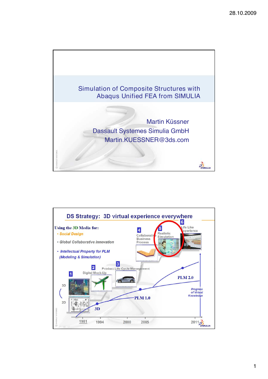
DS Strategy: 3D virtual experience everywhere
2
1
�
DS Brands
3D
MCAD
Virtual
Product
Virtual
Testing
Virtual
Production
PLM
User
Collaboration
Experience
P
h
o
o
t
c
o
u
r
t
Productive, Easy-
to-use 3D Design
Product
Excellence
Realistic
Simulation
Production
Performance
Collaborative
Intelligence
Lifelike
Experience
e
s
y
o
f
B
M
W
Abaqus Product Line
Abaqus/CAE
Interactive, parametric, finite element
modeler and results viewer
Abaqus/Standard
Linear and nonlinear statics, dynamics,
acoustics, and heat transfer
Abaqus/Explicit
Transient, very large deformation, highly
nonlinear simulations
Tightly integrated with Abaqus/Standard
Abaqus for CATIA V5
Access to Abaqus technology from within
the V5 environment
28.10.2009
2
�
Industry trends
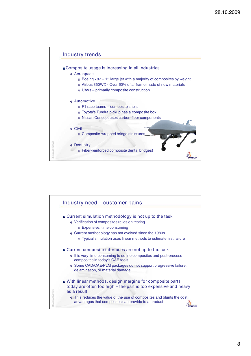
Composite usage is increasing in all industries
Aerospace
Boeing 787 – 1st large jet with a majority of composites by weight
Airbus 350WX - Over 60% of airframe made of new materials
UAVs – primarily composite construction
Automotive
F1 race teams – composite shells
Toyota's Tundra pickup has a composite box
Nissan Concept uses carbon-fiber components
Civil
Composite-wrapped bridge structures
Dentistry
Fiber-reinforced composite dental bridges!
Industry need – customer pains
Current simulation methodology is not up to the task
Verification of composites relies on testing
Expensive, time consuming
Current methodology has not evolved since the 1980s
Typical simulation uses linear methods to estimate first failure
Current composite interfaces are not up to the task
It is very time consuming to define composites and post-process
composites in today's CAE tools
Some CAD/CAE/PLM packages do not support progressive failure,
delamination, or material damage
With linear methods, design margins for composite parts
today are often too high – the part is too expensive and heavy
as a result
This reduces the value of the use of composites and blunts the cost
advantages that composites can provide to a product
28.10.2009
3
�
Abaqus Composite Solution mission statement
Abaqus solution for our customers:
Perform advanced composite simulations including static and
dynamic analysis that includes linear, nonlinear, and damage /
fracture /failure within a single environment
Predict the stiffness, first-failure, strength, and post-failure behavior
at the component and full-vehicle structural scale of complex
composite products
Simulate low- (from tool drop or hail), medium- (from runway debris),
or high-velocity (ballistic penetration) events including Barely Visible
Impact Damage (BVID) and Bird Strike
Have the very best in composite modeling, visualization, and post-
processing through /CAE's new ply-based interfaces
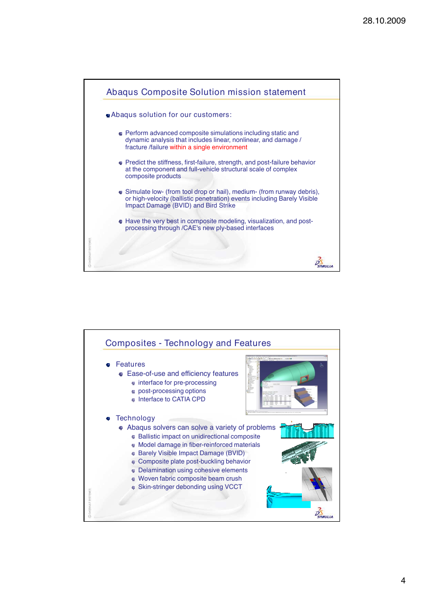
Composites - Technology and Features
Features
Ease-of-use and efficiency features
interface for pre-processing
post-processing options
Interface to CATIA CPD
Technology
Abaqus solvers can solve a variety of problems
Ballistic impact on unidirectional composite
Model damage in fiber-reinforced materials
Barely Visible Impact Damage (BVID)
Composite plate post-buckling behavior
Delamination using cohesive elements
Woven fabric composite beam crush
Skin-stringer debonding using VCCT
28.10.2009
4
�
28.10.2009
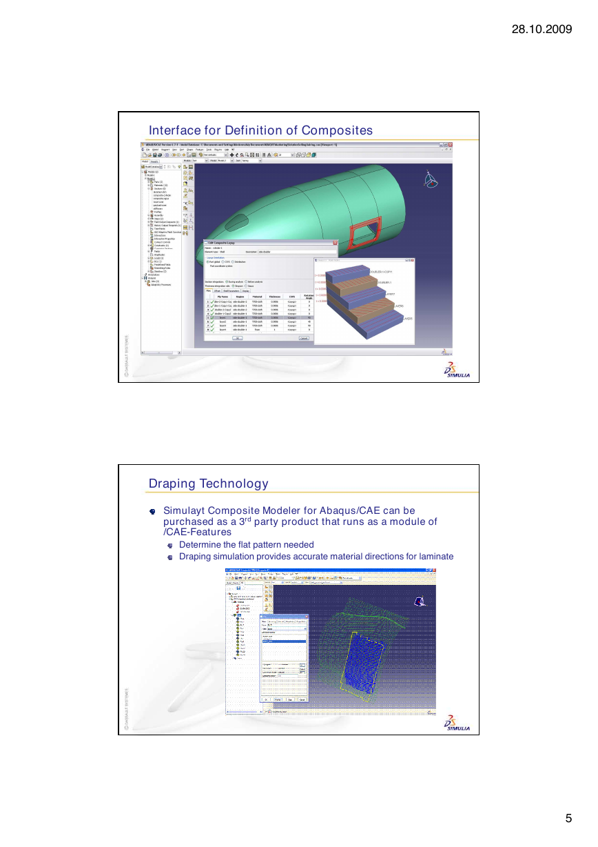
Interface for Definition of Composites
Draping Technology
Simulayt Composite Modeler for Abaqus/CAE can be
purchased as a 3rd party product that runs as a module of
/CAE-Features
Determine the flat pattern needed
Draping simulation provides accurate material directions for laminate
5
�
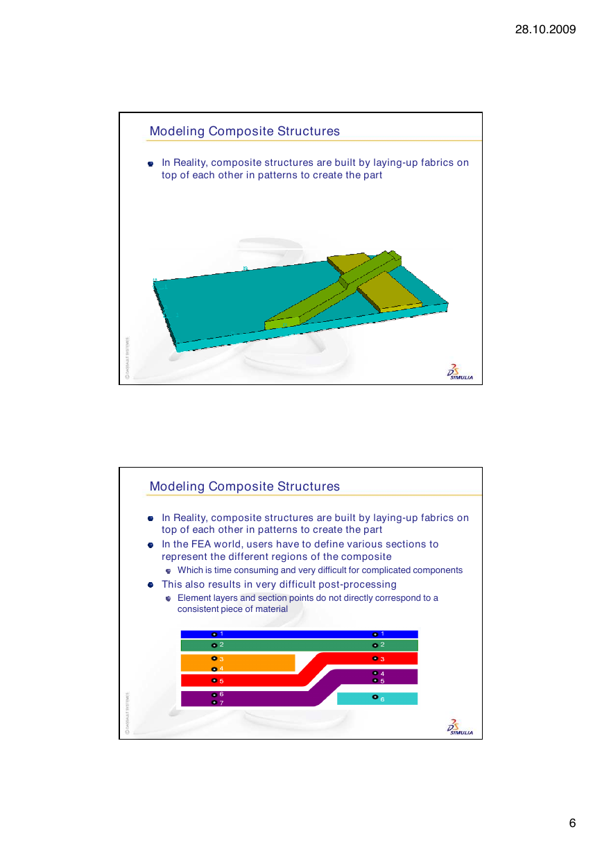
Modeling Composite Structures
In Reality, composite structures are built by laying-up fabrics on
top of each other in patterns to create the part
Modeling Composite Structures
In Reality, composite structures are built by laying-up fabrics on
top of each other in patterns to create the part
In the FEA world, users have to define various sections to
represent the different regions of the composite
Which is time consuming and very difficult for complicated components
This also results in very difficult post-processing
Element layers and section points do not directly correspond to a
consistent piece of material
28.10.2009
6
�
Users Can Now Model in Terms of Plies
Think in terms of “Plies”
Representation of the materials as placed in a mold
User supplied ply name is available in ODB and /Viewer for easy
tracking in post-processing operations
Plies defined on picked regions or named sets of partitioned
geometry or orphan mesh parts
Ply-1
Ply-2
Ply-3
Composite modeling in Abaqus
Composite Layup Object
Part level replacement for multiple sections, section assignments
and material orientations for layered composites - in one object
Advantages:
Ply-based
More intuitive definition of
ply regions than “artificial”
section assignments
Output requests can be
defined by composite layup
Suppressible
Supports shell, layered continuum shell and layered solid
elements
28.10.2009
7
�
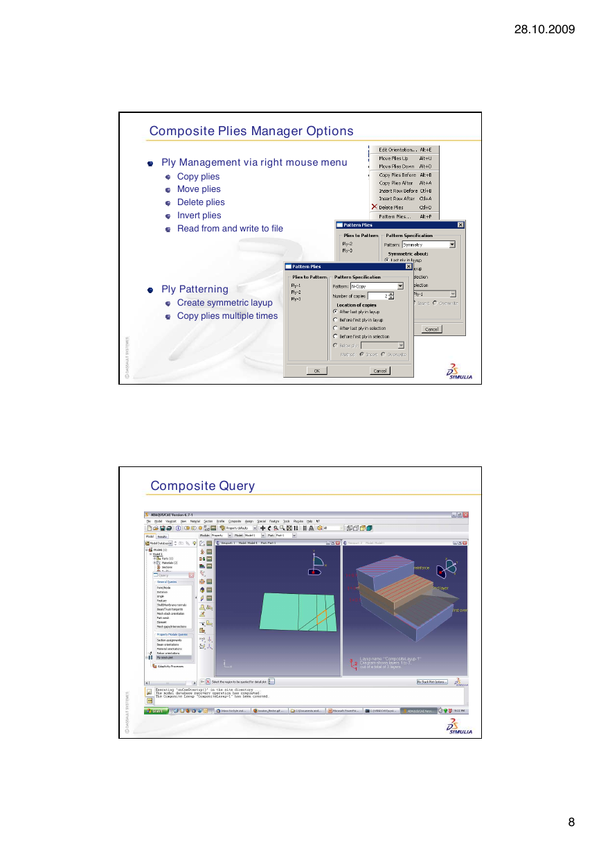
Composite Plies Manager Options
Ply Management via right mouse menu
Copy plies
Move plies
Delete plies
Invert plies
Read from and write to file
Ply Patterning
Create symmetric layup
Copy plies multiple times
Composite Query
28.10.2009
8
�




 2023年江西萍乡中考道德与法治真题及答案.doc
 2012年重庆南川中考生物真题及答案.doc
 2013年江西师范大学地理学综合及文艺理论基础考研真题.doc
 2020年四川甘孜小升初语文真题及答案I卷.doc
 2020年注册岩土工程师专业基础考试真题及答案.doc
 2023-2024学年福建省厦门市九年级上学期数学月考试题及答案.doc
 2021-2022学年辽宁省沈阳市大东区九年级上学期语文期末试题及答案.doc
 2022-2023学年北京东城区初三第一学期物理期末试卷及答案.doc
 2018上半年江西教师资格初中地理学科知识与教学能力真题及答案.doc
 2012年河北国家公务员申论考试真题及答案-省级.doc
 2020-2021学年江苏省扬州市江都区邵樊片九年级上学期数学第一次质量检测试题及答案.doc
 2022下半年黑龙江教师资格证中学综合素质真题及答案.doc