JEDEC
STANDARD
DDR2 SDRAM SPECIFICATION
Allwinnertech
JESD79-2F
(Revision of JESD79-2E)
November 2009
JEDEC SOLID STATE TECHNOLOGY ASSOCIATION
Downloaded by Yichun Zhao (zyjhandsome@126.com) on Apr 25, 2018, 5:34 pm PDT
�
NOTICE
JEDEC standards and publications contain material that has been prepared, reviewed, and
approved through the JEDEC Board of Directors level and subsequently reviewed and approved
by the JEDEC legal Counsel.
JEDEC standards and publications are designed to serve the public interest through eliminating
misunderstandings between manufacturers and purchasers, facilitating interchangeability and
improvement of products, and assisting the purchaser in selecting and obtaining with minimum
delay the proper product for use by those other than JEDEC members, whether the standard is to
be used either domestically or internationally.
JEDEC standards and publications are adopted without regard to whether or not their adoption
may involve patents or articles, materials, or processes. By such action JEDEC does not assume
any liability to any patent owner, nor does it assume any obligation whatever to parties adopting
The information included in JEDEC standards and publications represents a sound approach to
product specification and application, principally from the solid state device manufacturer
viewpoint. Within the JEDEC organization, there are procedures whereby a JEDEC standard or
publication mya be further processed and ultimately become an ANSI standard.
No claims to be in conformance with this standard may be made unless all requirements stated in
the JEDEC standards or publications.
Allwinnertech
the standard are met.
www.jedec.org.
Published by
Inquiries, comments, and suggestions relative to the content of this JEDEC standard or
publication should be addressed to JEDEC at the address below, or call (703) 907-7559 or
©JEDEC Solid State Technology Association 2009
3103 North 10th Street, Suite 240-S
Arlington, VA 22201
This document may be downloaded free of charge, however JEDEC retains the
copyright on this material. By downloading this file the individual agrees not to
charge for or resell the resulting material.
Price: Please refer to the current
Catalog of JEDEC Engineering Standards and Publications online at
http://www.jedec.org/Catalog/catalog.cfm
Printed in the U.S.A.
All rights reserved
Downloaded by Yichun Zhao (zyjhandsome@126.com) on Apr 25, 2018, 5:34 pm PDT
�
P LE A S E !
D O N ’T V IO LA T E
T H E
LA W !
T his docum ent is copyrighted by the E lectronic Industries A lliance and m ay not be
reproduced w ithout perm ission.
O rganizations m ay obtain perm ission to reproduce a lim ited num ber of copies
through entering into a license agreem ent. F or inform ation, contact:
Allwinnertech
2500 W ilson B oulevard
or call (703) 907-7559
A rlington, V irginia 22201-3834
JE D E C S olid S tate T echnology A ssociation
Downloaded by Yichun Zhao (zyjhandsome@126.com) on Apr 25, 2018, 5:34 pm PDT
�
This page intentionally left blank.
Allwinnertech
Downloaded by Yichun Zhao (zyjhandsome@126.com) on Apr 25, 2018, 5:34 pm PDT
�
JEDEC Standard No. 79-2F
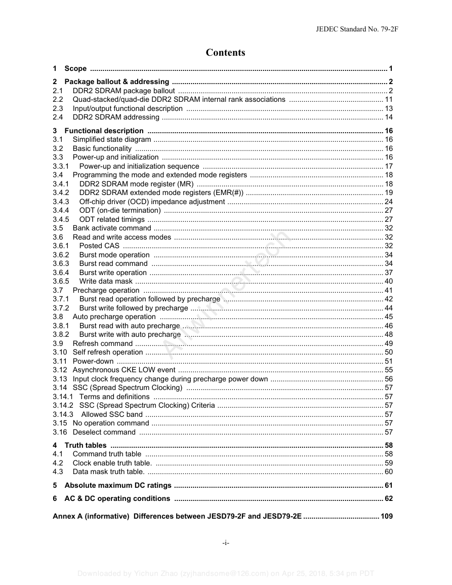
Contents
1 Scope ................................................................................................................................................. 1
2 Package ballout & addressing ......................................................................................................... 2
2.1 DDR2 SDRAM package ballout ...................................................................................................... 2
2.2 Quad-stacked/quad-die DDR2 SDRAM internal rank associations .............................................. 11
2.3
Input/output functional description ................................................................................................ 13
2.4 DDR2 SDRAM addressing ............................................................................................................ 14
3 Functional description ................................................................................................................... 16
3.1 Simplified state diagram ................................................................................................................ 16
3.2 Basic functionality ......................................................................................................................... 16
3.3 Power-up and initialization ............................................................................................................ 16
3.3.1
Power-up and initialization sequence ........................................................................................ 17
3.4 Programming the mode and extended mode registers ................................................................. 18
3.4.1 DDR2 SDRAM mode register (MR) ........................................................................................... 18
3.4.2 DDR2 SDRAM extended mode registers (EMR(#)) ................................................................... 19
3.4.3 Off-chip driver (OCD) impedance adjustment ............................................................................ 24
3.4.4 ODT (on-die termination) ........................................................................................................... 27
3.4.5 ODT related timings ................................................................................................................... 27
3.5 Bank activate command ................................................................................................................ 32
3.6 Read and write access modes ...................................................................................................... 32
3.6.1
Posted CAS ............................................................................................................................... 32
Burst mode operation ................................................................................................................ 34
3.6.2
Burst read command ................................................................................................................. 34
3.6.3
3.6.4
Burst write operation .................................................................................................................. 37
3.6.5 Write data mask ......................................................................................................................... 40
3.7 Precharge operation ..................................................................................................................... 41
Burst read operation followed by precharge .............................................................................. 42
3.7.1
3.7.2
Burst write followed by precharge .............................................................................................. 44
3.8 Auto precharge operation ............................................................................................................. 45
Burst read with auto precharge .................................................................................................. 46
3.8.1
3.8.2
Burst write with auto precharge ................................................................................................. 48
3.9 Refresh command ......................................................................................................................... 49
3.10 Self refresh operation .................................................................................................................... 50
3.11 Power-down .................................................................................................................................. 51
3.12 Asynchronous CKE LOW event .................................................................................................... 55
3.13 Input clock frequency change during precharge power down ....................................................... 56
3.14 SSC (Spread Spectrum Clocking) ................................................................................................ 57
3.14.1 Terms and definitions ................................................................................................................ 57
3.14.2 SSC (Spread Spectrum Clocking) Criteria ................................................................................. 57
3.14.3 Allowed SSC band .................................................................................................................... 57
3.15 No operation command ................................................................................................................. 57
3.16 Deselect command ....................................................................................................................... 57
4 Truth tables ..................................................................................................................................... 58
4.1 Command truth table .................................................................................................................... 58
4.2 Clock enable truth table. ............................................................................................................... 59
4.3 Data mask truth table. ................................................................................................................... 60
5 Absolute maximum DC ratings ...................................................................................................... 61
6 AC & DC operating conditions ...................................................................................................... 62
Allwinnertech
Annex A (informative) Differences between JESD79-2F and JESD79-2E ..................................... 109
-i-
Downloaded by Yichun Zhao (zyjhandsome@126.com) on Apr 25, 2018, 5:34 pm PDT
�
JEDEC Standard No. 79-2F
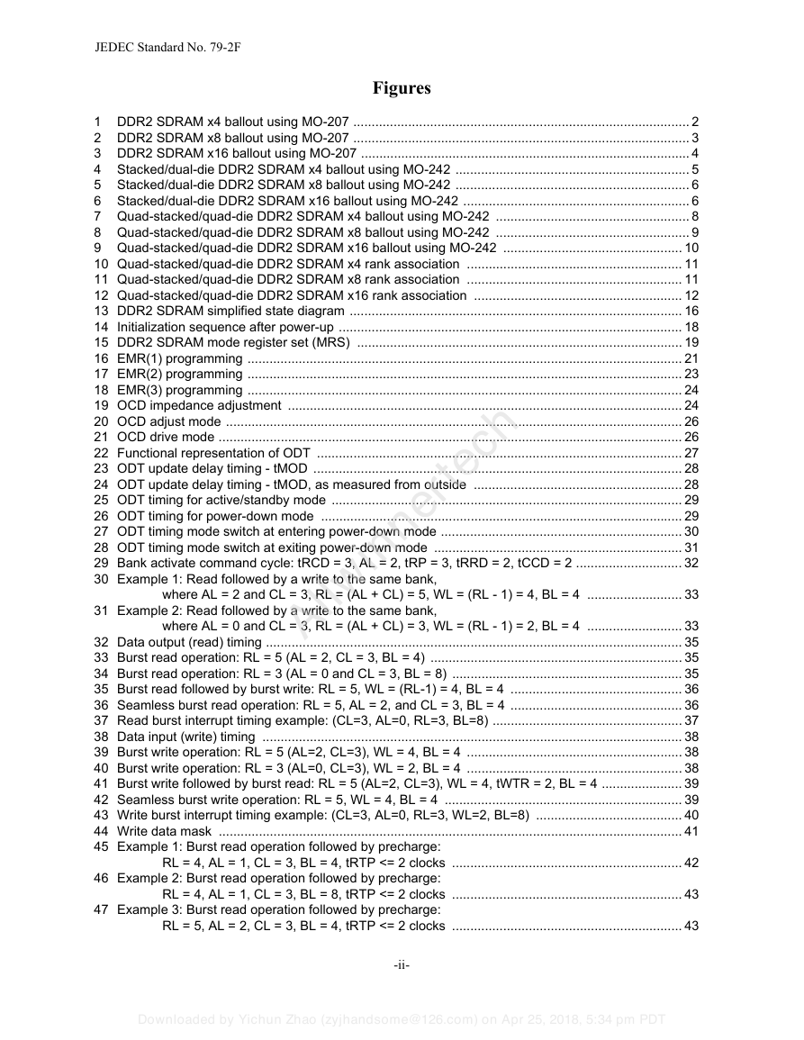
Figures
1 DDR2 SDRAM x4 ballout using MO-207 ............................................................................................ 2
2 DDR2 SDRAM x8 ballout using MO-207 ............................................................................................ 3
3 DDR2 SDRAM x16 ballout using MO-207 .......................................................................................... 4
4 Stacked/dual-die DDR2 SDRAM x4 ballout using MO-242 ................................................................ 5
5 Stacked/dual-die DDR2 SDRAM x8 ballout using MO-242 ................................................................ 6
6 Stacked/dual-die DDR2 SDRAM x16 ballout using MO-242 .............................................................. 6
7 Quad-stacked/quad-die DDR2 SDRAM x4 ballout using MO-242 ..................................................... 8
8 Quad-stacked/quad-die DDR2 SDRAM x8 ballout using MO-242 ..................................................... 9
9 Quad-stacked/quad-die DDR2 SDRAM x16 ballout using MO-242 ................................................. 10
10 Quad-stacked/quad-die DDR2 SDRAM x4 rank association ........................................................... 11
11 Quad-stacked/quad-die DDR2 SDRAM x8 rank association ........................................................... 11
12 Quad-stacked/quad-die DDR2 SDRAM x16 rank association ......................................................... 12
13 DDR2 SDRAM simplified state diagram ........................................................................................... 16
14 Initialization sequence after power-up .............................................................................................. 18
15 DDR2 SDRAM mode register set (MRS) ......................................................................................... 19
16 EMR(1) programming ....................................................................................................................... 21
17 EMR(2) programming ....................................................................................................................... 23
18 EMR(3) programming ....................................................................................................................... 24
19 OCD impedance adjustment ............................................................................................................ 24
20 OCD adjust mode ............................................................................................................................. 26
21 OCD drive mode ............................................................................................................................... 26
22 Functional representation of ODT .................................................................................................... 27
23 ODT update delay timing - tMOD ..................................................................................................... 28
24 ODT update delay timing - tMOD, as measured from outside ......................................................... 28
25 ODT timing for active/standby mode ................................................................................................ 29
26 ODT timing for power-down mode ................................................................................................... 29
27 ODT timing mode switch at entering power-down mode .................................................................. 30
28 ODT timing mode switch at exiting power-down mode .................................................................... 31
29 Bank activate command cycle: tRCD = 3, AL = 2, tRP = 3, tRRD = 2, tCCD = 2 ............................. 32
30 Example 1: Read followed by a write to the same bank,
Allwinnertech
where AL = 2 and CL = 3, RL = (AL + CL) = 5, WL = (RL - 1) = 4, BL = 4 .......................... 33
31 Example 2: Read followed by a write to the same bank,
where AL = 0 and CL = 3, RL = (AL + CL) = 3, WL = (RL - 1) = 2, BL = 4 .......................... 33
32 Data output (read) timing .................................................................................................................. 35
33 Burst read operation: RL = 5 (AL = 2, CL = 3, BL = 4) ..................................................................... 35
34 Burst read operation: RL = 3 (AL = 0 and CL = 3, BL = 8) ............................................................... 35
35 Burst read followed by burst write: RL = 5, WL = (RL-1) = 4, BL = 4 ............................................... 36
36 Seamless burst read operation: RL = 5, AL = 2, and CL = 3, BL = 4 ............................................... 36
37 Read burst interrupt timing example: (CL=3, AL=0, RL=3, BL=8) .................................................... 37
38 Data input (write) timing ................................................................................................................... 38
39 Burst write operation: RL = 5 (AL=2, CL=3), WL = 4, BL = 4 ........................................................... 38
40 Burst write operation: RL = 3 (AL=0, CL=3), WL = 2, BL = 4 ........................................................... 38
41 Burst write followed by burst read: RL = 5 (AL=2, CL=3), WL = 4, tWTR = 2, BL = 4 ...................... 39
42 Seamless burst write operation: RL = 5, WL = 4, BL = 4 ................................................................. 39
43 Write burst interrupt timing example: (CL=3, AL=0, RL=3, WL=2, BL=8) ........................................ 40
44 Write data mask ............................................................................................................................... 41
45 Example 1: Burst read operation followed by precharge:
RL = 4, AL = 1, CL = 3, BL = 4, tRTP <= 2 clocks ............................................................... 42
46 Example 2: Burst read operation followed by precharge:
RL = 4, AL = 1, CL = 3, BL = 8, tRTP <= 2 clocks ............................................................... 43
47 Example 3: Burst read operation followed by precharge:
RL = 5, AL = 2, CL = 3, BL = 4, tRTP <= 2 clocks ............................................................... 43
-ii-
Downloaded by Yichun Zhao (zyjhandsome@126.com) on Apr 25, 2018, 5:34 pm PDT
�
JEDEC Standard No. 79-2F
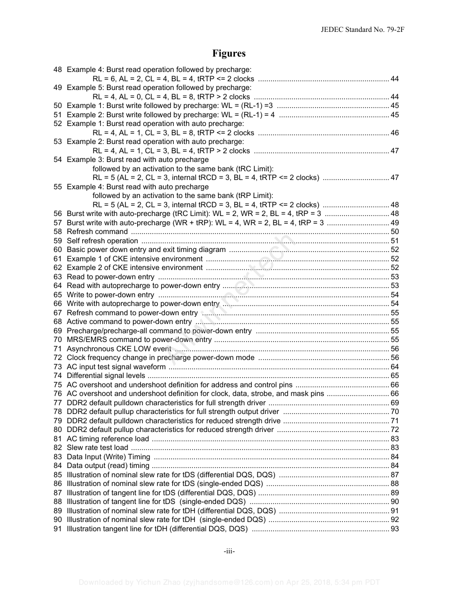
Figures
48 Example 4: Burst read operation followed by precharge:
RL = 6, AL = 2, CL = 4, BL = 4, tRTP <= 2 clocks ............................................................... 44
49 Example 5: Burst read operation followed by precharge:
RL = 4, AL = 0, CL = 4, BL = 8, tRTP > 2 clocks ................................................................. 44
50 Example 1: Burst write followed by precharge: WL = (RL-1) =3 ...................................................... 45
51 Example 2: Burst write followed by precharge: WL = (RL-1) = 4 ..................................................... 45
52 Example 1: Burst read operation with auto precharge:
RL = 4, AL = 1, CL = 3, BL = 8, tRTP <= 2 clocks ............................................................... 46
53 Example 2: Burst read operation with auto precharge:
RL = 4, AL = 1, CL = 3, BL = 4, tRTP > 2 clocks ................................................................. 47
54 Example 3: Burst read with auto precharge
followed by an activation to the same bank (tRC Limit):
RL = 5 (AL = 2, CL = 3, internal tRCD = 3, BL = 4, tRTP <= 2 clocks) ................................ 47
55 Example 4: Burst read with auto precharge
Allwinnertech
followed by an activation to the same bank (tRP Limit):
RL = 5 (AL = 2, CL = 3, internal tRCD = 3, BL = 4, tRTP <= 2 clocks) ................................ 48
56 Burst write with auto-precharge (tRC Limit): WL = 2, WR = 2, BL = 4, tRP = 3 ............................... 48
57 Burst write with auto-precharge (WR + tRP): WL = 4, WR = 2, BL = 4, tRP = 3 .............................. 49
58 Refresh command ............................................................................................................................ 50
59 Self refresh operation ....................................................................................................................... 51
60 Basic power down entry and exit timing diagram ............................................................................. 52
61 Example 1 of CKE intensive environment ........................................................................................ 52
62 Example 2 of CKE intensive environment ........................................................................................ 52
63 Read to power-down entry ............................................................................................................... 53
64 Read with autoprecharge to power-down entry ................................................................................ 53
65 Write to power-down entry ............................................................................................................... 54
66 Write with autoprecharge to power-down entry ................................................................................ 54
67 Refresh command to power-down entry .......................................................................................... 55
68 Active command to power-down entry ............................................................................................. 55
69 Precharge/precharge-all command to power-down entry ................................................................ 55
70 MRS/EMRS command to power-down entry .................................................................................... 55
71 Asynchronous CKE LOW event ....................................................................................................... 56
72 Clock frequency change in precharge power-down mode ............................................................... 56
73 AC input test signal waveform .......................................................................................................... 64
74 Differential signal levels .................................................................................................................... 65
75 AC overshoot and undershoot definition for address and control pins ............................................. 66
76 AC overshoot and undershoot definition for clock, data, strobe, and mask pins .............................. 66
77 DDR2 default pulldown characteristics for full strength driver .......................................................... 69
78 DDR2 default pullup characteristics for full strength output driver ................................................... 70
79 DDR2 default pulldown characteristics for reduced strength drive ................................................... 71
80 DDR2 default pullup characteristics for reduced strength driver ...................................................... 72
81 AC timing reference load .................................................................................................................. 83
82 Slew rate test load ............................................................................................................................ 83
83 Data Input (Write) Timing ................................................................................................................. 84
84 Data output (read) timing .................................................................................................................. 84
85 Illustration of nominal slew rate for tDS (differential DQS, DQS) ..................................................... 87
86 Illustration of nominal slew rate for tDS (single-ended DQS) ........................................................... 88
87 Illustration of tangent line for tDS (differential DQS, DQS) ............................................................... 89
88 Illustration of tangent line for tDS (single-ended DQS) ................................................................... 90
89 Illustration of nominal slew rate for tDH (differential DQS, DQS) ..................................................... 91
90 Illustration of nominal slew rate for tDH (single-ended DQS) .......................................................... 92
91 Illustration tangent line for tDH (differential DQS, DQS) .................................................................. 93
-iii-
Downloaded by Yichun Zhao (zyjhandsome@126.com) on Apr 25, 2018, 5:34 pm PDT
�
JEDEC Standard No. 79-2F
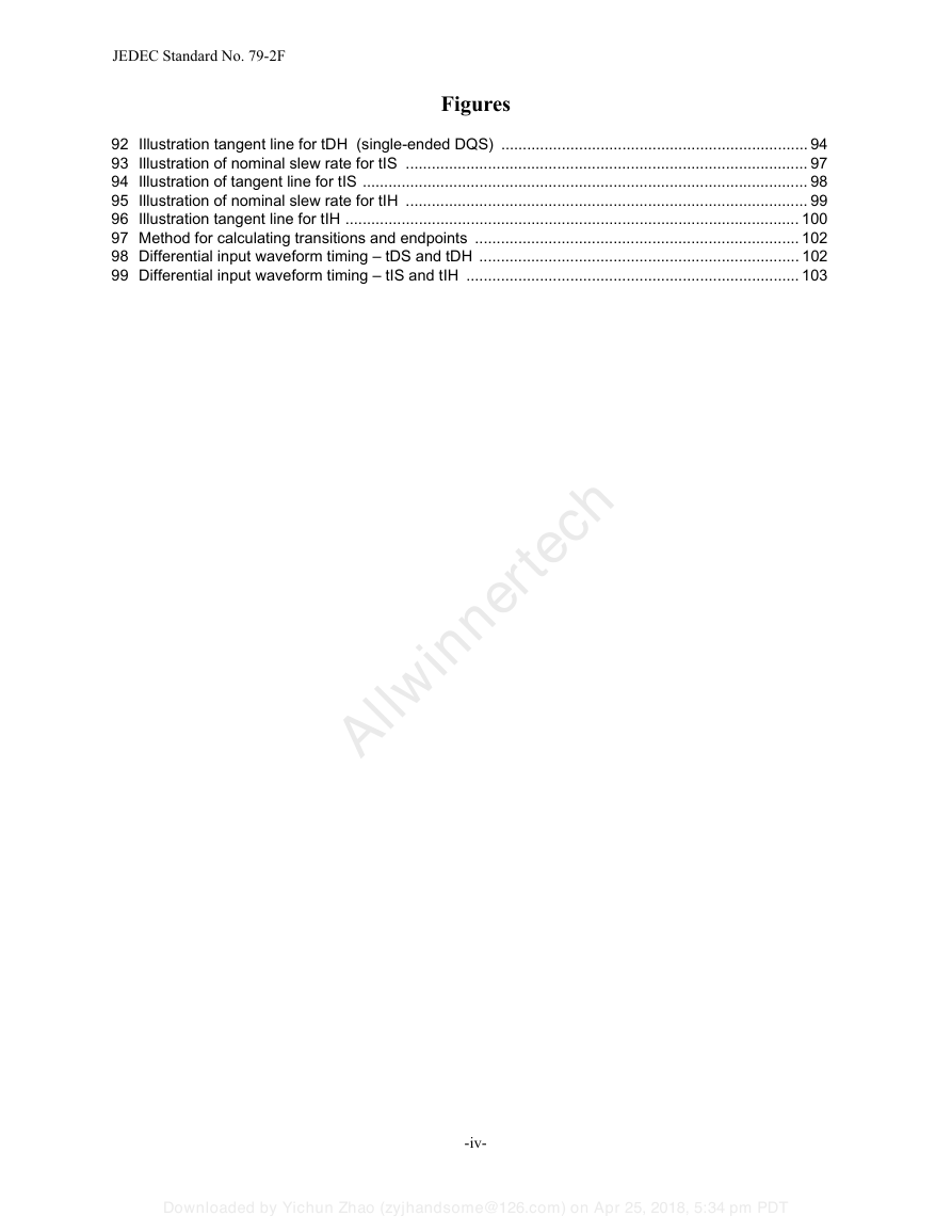
Figures
92 Illustration tangent line for tDH (single-ended DQS) ....................................................................... 94
93 Illustration of nominal slew rate for tIS ............................................................................................. 97
94 Illustration of tangent line for tIS ....................................................................................................... 98
95 Illustration of nominal slew rate for tIH ............................................................................................. 99
96 Illustration tangent line for tIH ......................................................................................................... 100
97 Method for calculating transitions and endpoints ........................................................................... 102
98 Differential input waveform timing – tDS and tDH .......................................................................... 102
99 Differential input waveform timing – tIS and tIH ............................................................................. 103
Allwinnertech
-iv-
Downloaded by Yichun Zhao (zyjhandsome@126.com) on Apr 25, 2018, 5:34 pm PDT
�



 2023年江西萍乡中考道德与法治真题及答案.doc
 2012年重庆南川中考生物真题及答案.doc
 2013年江西师范大学地理学综合及文艺理论基础考研真题.doc
 2020年四川甘孜小升初语文真题及答案I卷.doc
 2020年注册岩土工程师专业基础考试真题及答案.doc
 2023-2024学年福建省厦门市九年级上学期数学月考试题及答案.doc
 2021-2022学年辽宁省沈阳市大东区九年级上学期语文期末试题及答案.doc
 2022-2023学年北京东城区初三第一学期物理期末试卷及答案.doc
 2018上半年江西教师资格初中地理学科知识与教学能力真题及答案.doc
 2012年河北国家公务员申论考试真题及答案-省级.doc
 2020-2021学年江苏省扬州市江都区邵樊片九年级上学期数学第一次质量检测试题及答案.doc
 2022下半年黑龙江教师资格证中学综合素质真题及答案.doc