GPS Engine Board Manual
SR-96 Manual V1.1.1
SSSSR-96R-96R-96R-96
SiRF StarⅢⅢⅢⅢ
V 1.1.1
Made in Taiwan
2008/08/08
service@dagamagps.com
www.dagamagps.com
Free service hot-line(for mainland):400-820-1322
�
SR-96 Manual V1.1.1
Specifications subject to
change without prior notice!
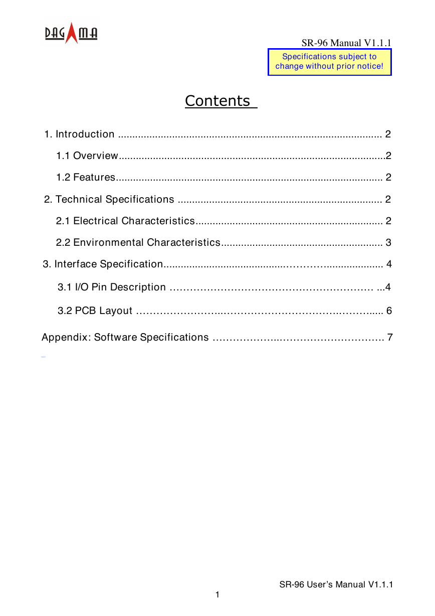
Contents
1. Introduction ............................................................................................. 2
1.1 Overview..............................................................................................2
1.2 Features.............................................................................................. 2
2. Technical Specifications ........................................................................ 2
2.1 Electrical Characteristics.................................................................. 2
2.2 Environmental Characteristics......................................................... 3
3. Interface Specification...........................................………….................... 4
3.1 I/O Pin Description …………………………………………………… ...4
3.2 PCB Layout ……………………..…………………………….………..... 6
Appendix: Software Specifications ………………..…………………………. 7
1
SR-96 User’s Manual V1.1.1
�
1. Introduction
1.1 Overview
SR-96 Manual V1.1.1
SR-96 GPS module is a high performance receiver module for the Global Positioning
System (GPS) solution providing latitude, longitude, height, time and velocity data.
The smart type module has patch antenna, LNA (Low Noise amplifier) and saw filter.
It has High performance and Low power consumption, extremely small size. The
module design is base on low power consumption, high sensitivity SiRF StarⅢ chipset.
It can be easily embedded into portable devices for GPS wireless communication.
1.2 Features
☼ Full self-contained GPS receiver
☼ Fully shielded design
☼ Full implementation of SiRF StarⅢ GPS architecture
☼ GSC3F/LP(High Performance GPS Single Chip)
☼ GPS DSP with integrated real time clock (RTC) ARM7TDMI CPU
☼ 4Mbit FLASH memory
☼ Low noise amplifier
☼ SAW filter
☼ TCXO
GPS receiver in a micro-component package
☼ Fully automatic assembly: Reflow solderable
☼ No RF connector
☼ Size: 13.1mm X 15.9mm X 2.7mm
☼ Weight: 1.1 grams
Ordering information:
SR-96-J GPS module with supply regulator enable, supply voltage 3.0~4.2V
SR-96-S GPS module without regulator, supply voltage 3.0~3.5V
2. Technical Specifications
2.1. Electrical Characteristics
2.1.1 General
Frequency
C/A code
Channels
2.1.2 Sensitivity
L1, 1575.42 MHz
1.023 MHz chip rate
20 channels all in view tracking
2
SR-96 User’s Manual V1.1.1
�
SR-96 Manual V1.1.1
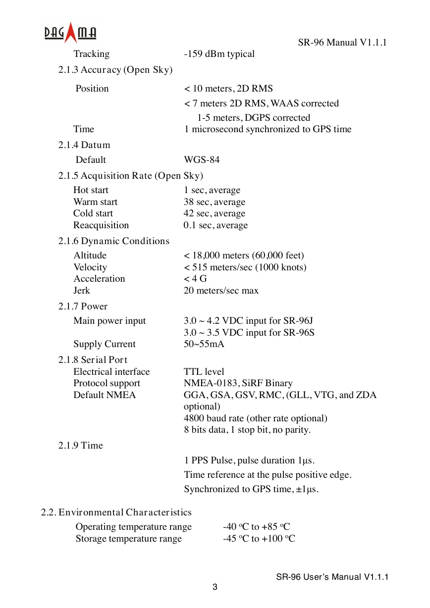
Tracking
-159 dBm typical
2.1.3 Accuracy (Open Sky)
Position
Time
2.1.4 Datum
Default
< 10 meters, 2D RMS
< 7 meters 2D RMS, WAAS corrected
1-5 meters, DGPS corrected
1 microsecond synchronized to GPS time
WGS-84
2.1.5 Acquisition Rate (Open Sky)
Hot start
Warm start
Cold start
Reacquisition
1 sec, average
38 sec, average
42 sec, average
0.1 sec, average
2.1.6 Dynamic Conditions
Altitude
Velocity
Acceleration
Jerk
2.1.7 Power
Main power input
Supply Current
2.1.8 Serial Port
Electrical interface
Protocol support
Default NMEA
2.1.9 Time
< 18,000 meters (60,000 feet)
< 515 meters/sec (1000 knots)
< 4 G
20 meters/sec max
3.0 ~ 4.2 VDC input for SR-96J
3.0 ~ 3.5 VDC input for SR-96S
50~55mA
TTL level
NMEA-0183, SiRF Binary
GGA, GSA, GSV, RMC, (GLL, VTG, and ZDA
optional)
4800 baud rate (other rate optional)
8 bits data, 1 stop bit, no parity.
1 PPS Pulse, pulse duration 1µs.
Time reference at the pulse positive edge.
Synchronized to GPS time, ±1µs.
2.2. Environmental Characteristics
Operating temperature range
Storage temperature range
-40 oC to +85 oC
-45 oC to +100 oC
3
SR-96 User’s Manual V1.1.1
�
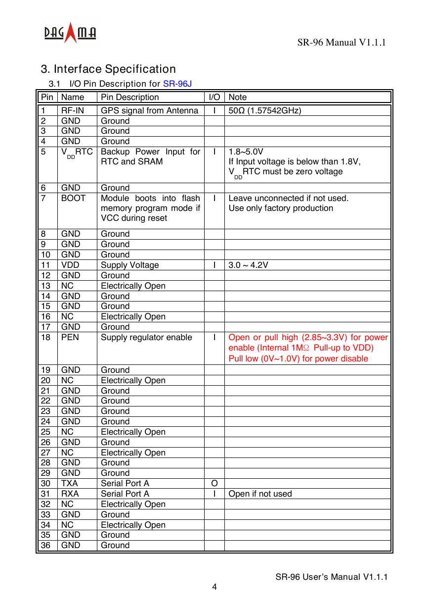
3. Interface Specification
3.1 I/O Pin Description for SR-96J
SR-96 Manual V1.1.1
Pin Name
RF-IN
1
GND
2
3
GND
GND
4
5
V
DD
Pin Description
GPS signal from Antenna
Ground
Ground
Ground
I/O Note
I
50Ω (1.57542GHz)
RTC Backup Power Input
for
RTC and SRAM
6
7
GND
BOOT
GND
8
9
GND
10 GND
11 VDD
12 GND
13 NC
14 GND
15 GND
16 NC
17 GND
18 PEN
19 GND
20 NC
21 GND
22 GND
23 GND
24 GND
25 NC
26 GND
27 NC
28 GND
29 GND
30
TXA
31 RXA
32 NC
33 GND
34 NC
35 GND
36 GND
Ground
Module boots into flash
memory program mode if
VCC during reset
Ground
Ground
Ground
Supply Voltage
Ground
Electrically Open
Ground
Ground
Electrically Open
Ground
Supply regulator enable
Ground
Electrically Open
Ground
Ground
Ground
Ground
Electrically Open
Ground
Electrically Open
Ground
Ground
Serial Port A
Serial Port A
Electrically Open
Ground
Electrically Open
Ground
Ground
I
I
1.8~5.0V
If Input voltage is below than 1.8V,
V
RTC must be zero voltage
DD
Leave unconnected if not used.
Use only factory production
I
3.0 ~ 4.2V
I Open or pull high (2.85~3.3V) for power
enable (Internal 1MΩ Pull-up to VDD)
Pull low (0V~1.0V) for power disable
O
I Open if not used
4
SR-96 User’s Manual V1.1.1
�
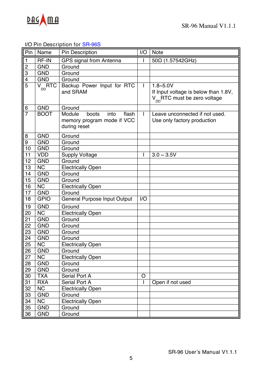
I/O Pin Description for SR-96S
Pin Name
RF-IN
1
GND
2
GND
3
4
GND
V
5
Pin Description
GPS signal from Antenna
Ground
Ground
Ground
RTC Backup Power Input
for RTC
DD
and SRAM
SR-96 Manual V1.1.1
I/O Note
I
50Ω (1.57542GHz)
I
I
1.8~5.0V
If Input voltage is below than 1.8V,
V
RTC must be zero voltage
DD
Leave unconnected if not used.
Use only factory production
6
7
GND
BOOT
GND
8
GND
9
10 GND
11 VDD
12 GND
13 NC
14 GND
15 GND
16 NC
17 GND
18 GPIO
19 GND
20 NC
21 GND
22 GND
23 GND
24 GND
25 NC
26 GND
27 NC
28 GND
29 GND
30
TXA
31 RXA
32 NC
33 GND
34 NC
35 GND
36 GND
Ground
Module
flash
memory program mode if VCC
during reset
boots
into
Ground
Ground
Ground
Supply Voltage
Ground
Electrically Open
Ground
Ground
Electrically Open
Ground
General Purpose Input Output
Ground
Electrically Open
Ground
Ground
Ground
Ground
Electrically Open
Ground
Electrically Open
Ground
Ground
Serial Port A
Serial Port A
Electrically Open
Ground
Electrically Open
Ground
Ground
I
3.0 ~ 3.5V
I/O
O
I Open if not used
5
SR-96 User’s Manual V1.1.1
�
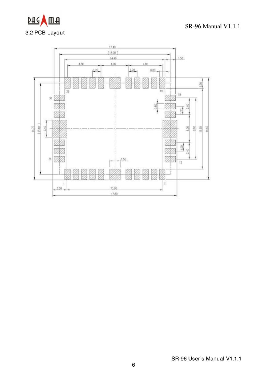
3.2 PCB Layout
SR-96 Manual V1.1.1
6
SR-96 User’s Manual V1.1.1
�
Appendix: Software Specifications
SR-96 Manual V1.1.1
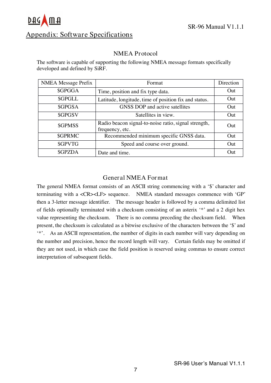
The software is capable of supporting the following NMEA message formats specifically
developed and defined by SiRF.
NMEA Protocol
NMEA Message Prefix
Format
Direction
$GPGGA
$GPGLL
$GPGSA
$GPGSV
$GPMSS
$GPRMC
$GPVTG
$GPZDA
Time, position and fix type data.
Latitude, longitude, time of position fix and status.
GNSS DOP and active satellites
Satellites in view.
Radio beacon signal-to-noise ratio, signal strength,
frequency, etc.
Recommended minimum specific GNSS data.
Speed and course over ground.
Date and time.
Out
Out
Out
Out
Out
Out
Out
Out
General NMEA Format
The general NMEA format consists of an ASCII string commencing with a ‘$’ character and
terminating with a sequence. NMEA standard messages commence with ‘GP’
then a 3-letter message identifier. The message header is followed by a comma delimited list
of fields optionally terminated with a checksum consisting of an asterix ‘*’ and a 2 digit hex
value representing the checksum. There is no comma preceding the checksum field. When
present, the checksum is calculated as a bitwise exclusive of the characters between the ‘$’ and
‘*’. As an ASCII representation, the number of digits in each number will vary depending on
the number and precision, hence the record length will vary. Certain fields may be omitted if
they are not used, in which case the field position is reserved using commas to ensure correct
interpretation of subsequent fields.
7
SR-96 User’s Manual V1.1.1
�




 2023年江西萍乡中考道德与法治真题及答案.doc
 2012年重庆南川中考生物真题及答案.doc
 2013年江西师范大学地理学综合及文艺理论基础考研真题.doc
 2020年四川甘孜小升初语文真题及答案I卷.doc
 2020年注册岩土工程师专业基础考试真题及答案.doc
 2023-2024学年福建省厦门市九年级上学期数学月考试题及答案.doc
 2021-2022学年辽宁省沈阳市大东区九年级上学期语文期末试题及答案.doc
 2022-2023学年北京东城区初三第一学期物理期末试卷及答案.doc
 2018上半年江西教师资格初中地理学科知识与教学能力真题及答案.doc
 2012年河北国家公务员申论考试真题及答案-省级.doc
 2020-2021学年江苏省扬州市江都区邵樊片九年级上学期数学第一次质量检测试题及答案.doc
 2022下半年黑龙江教师资格证中学综合素质真题及答案.doc