SR-89 Manual V1.0
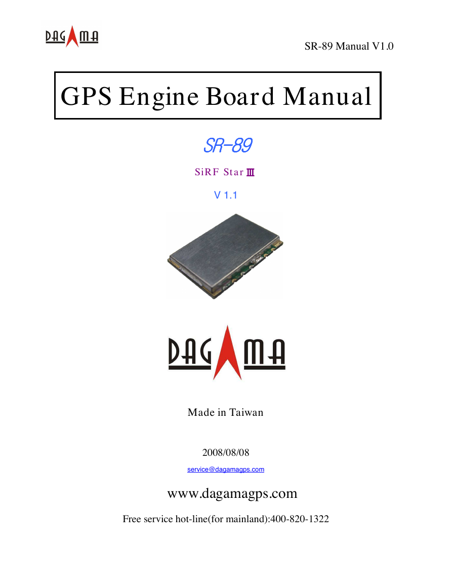
GPS Engine Board Manual
SSSSRRRR----88889999
SiRF Star ⅢⅢⅢⅢ
V 1.1
Made in Taiwan
2008/08/08
service@dagamagps.com
www.dagamagps.com
Free service hot-line(for mainland):400-820-1322
�
SR-89 Manual V1.0
Specifications subject to
change without prior notice!
Contents
1. Introduction ………………………………………………………..…………. 3
1.1 Overview ……………………………………………………………………. 3
2. Technical Specifications …………………………………………………… 4
2.1. Electrical Characteristics…………………………………………………. 4
2.2. Environmental Characteristics……………………………………..……… 5
2.3. Physical Characteristics……………………………………………...…..… 5
3. Applications ……………………………………………………………… 6
4. Operation and Test (optional) ………………..……………… 7
Appendix: Software Specifications ………………………………………..
8
2
SR-89 User’s Manual V1.1
�
1. Introduction
1.1. Overview
SR-89 Manual V1.0
Product Introduction
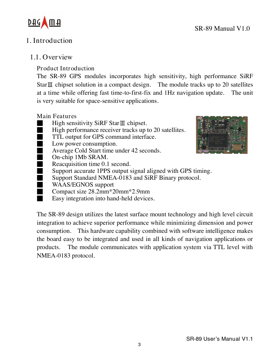
The SR-89 GPS modules incorporates high sensitivity, high performance SiRF
StarⅢ chipset solution in a compact design. The module tracks up to 20 satellites
at a time while offering fast time-to-first-fix and 1Hz navigation update. The unit
is very suitable for space-sensitive applications.
Main Features
■ High sensitivity SiRF StarⅢ chipset.
■ High performance receiver tracks up to 20 satellites.
■ TTL output for GPS command interface.
■ Low power consumption.
■ Average Cold Start time under 42 seconds.
■ On-chip 1Mb SRAM.
■ Reacquisition time 0.1 second.
■ Support accurate 1PPS output signal aligned with GPS timing.
■ Support Standard NMEA-0183 and SiRF Binary protocol.
■ WAAS/EGNOS support
■ Compact size 28.2mm*20mm*2.9mm
■ Easy integration into hand-held devices.
The SR-89 design utilizes the latest surface mount technology and high level circuit
integration to achieve superior performance while minimizing dimension and power
consumption. This hardware capability combined with software intelligence makes
the board easy to be integrated and used in all kinds of navigation applications or
products. The module communicates with application system via TTL level with
NMEA-0183 protocol.
3
SR-89 User’s Manual V1.1
�
SR-89 Manual V1.0
2. Technical Specifications
2.1. Electrical Characteristics
2.1.1 General
Frequency
C/A code
Channels
2.1.2 Sensitivity
Tracking
2.1.3 Accuracy (Open Sky)
L1, 1575.42 MHz
1.023 MHz chip rate
20 channels all in view tracking
-159 dBm typical
Position
Time
2.1.4 Datum
Default
< 10 meters, 2D RMS
< 7 meters 2D RMS, WAAS corrected
1-5 meters, DGPS corrected
1 microsecond synchronized to GPS time
WGS-84
2.1.5 Acquisition Rate (Open Sky)
Hot start
Warm start
Cold start
Reacquisition
1 sec, average
38 sec, average
42 sec, average
0.1 sec, average
2.1.6 Dynamic Conditions
Altitude
Velocity
Acceleration
Jerk
2.1.7 Power
< 18,000 meters (60,000 feet)
< 515 meters/sec (1000 knots)
< 4 G
20 meters/sec max
Main power input
Supply Current
3.3 VDC, ±5%
< 80 mA
4
SR-89 User’s Manual V1.1
�
2.1.8 Serial Port
Electrical interface
Protocol support
Default NMEA
2.1.9 Time
SR-89 Manual V1.0
TTL level
NMEA-0183, SiRF Binary
GGA, GSA, GSV, RMC, (GLL, VTG, and ZDA
optional)
4800 baud rate (other rate optional)
8 bits data, 1 stop bit, no parity.
1 PPS Pulse, pulse duration 1µs.
Time reference at the pulse positive edge.
Synchronized to GPS time, ±1µs.
2.2. Environmental Characteristics
Operating temperature range
Storage temperature range
-40 oC to +85 oC
-45 oC to +100 oC
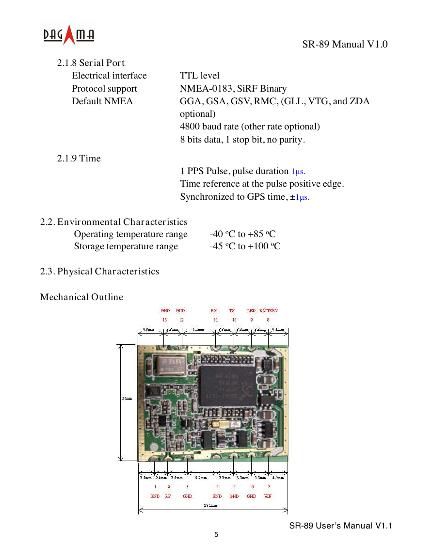
2.3. Physical Characteristics
Mechanical Outline
5
SR-89 User’s Manual V1.1
�
SR-89 Manual V1.0
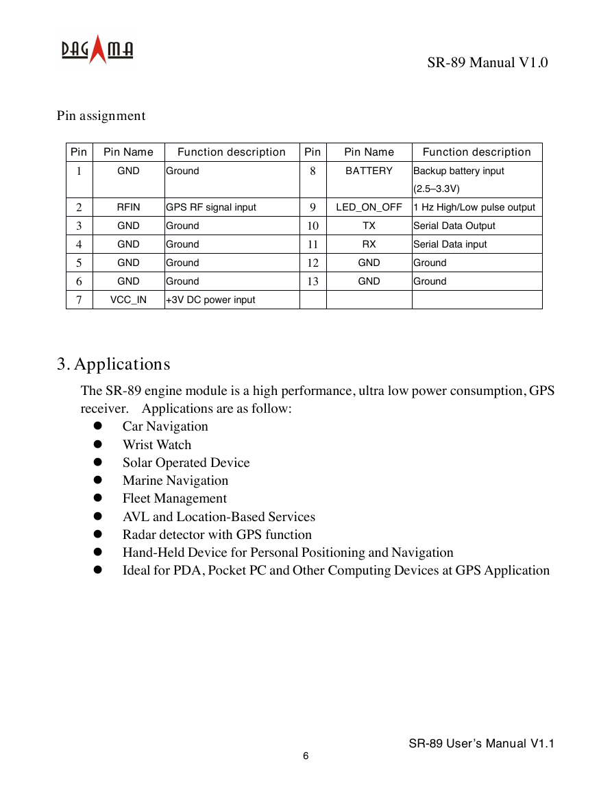
Pin assignment
Pin
1
2
3
4
5
6
7
Pin Name
Function description
GND
Ground
Pin
8
Pin Name
BATTERY
Function description
Backup battery input
(2.5–3.3V)
RFIN
GND
GND
GND
GND
GPS RF signal input
Ground
Ground
Ground
Ground
VCC_IN
+3V DC power input
9
10
11
12
13
LED_ON_OFF 1 Hz High/Low pulse output
TX
RX
GND
GND
Serial Data Output
Serial Data input
Ground
Ground
3. Applications
The SR-89 engine module is a high performance, ultra low power consumption, GPS
receiver. Applications are as follow:
� Car Navigation
� Wrist Watch
� Solar Operated Device
� Marine Navigation
� Fleet Management
� AVL and Location-Based Services
� Radar detector with GPS function
� Hand-Held Device for Personal Positioning and Navigation
� Ideal for PDA, Pocket PC and Other Computing Devices at GPS Application
6
SR-89 User’s Manual V1.1
�
SR-89 Manual V1.0
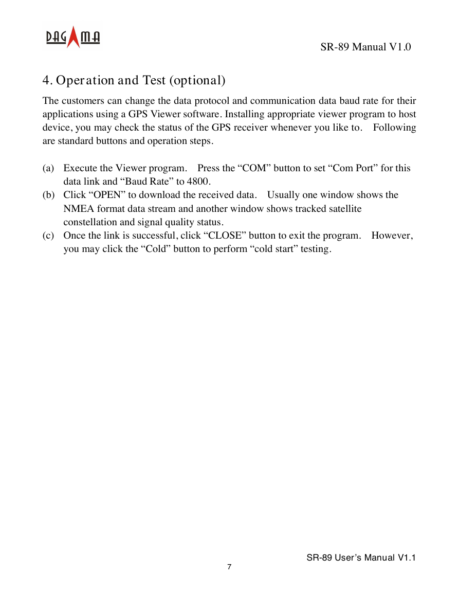
4. Operation and Test (optional)
The customers can change the data protocol and communication data baud rate for their
applications using a GPS Viewer software. Installing appropriate viewer program to host
device, you may check the status of the GPS receiver whenever you like to. Following
are standard buttons and operation steps.
(a) Execute the Viewer program. Press the “COM” button to set “Com Port” for this
data link and “Baud Rate” to 4800.
(b) Click “OPEN” to download the received data. Usually one window shows the
NMEA format data stream and another window shows tracked satellite
constellation and signal quality status.
(c) Once the link is successful, click “CLOSE” button to exit the program. However,
you may click the “Cold” button to perform “cold start” testing.
7
SR-89 User’s Manual V1.1
�
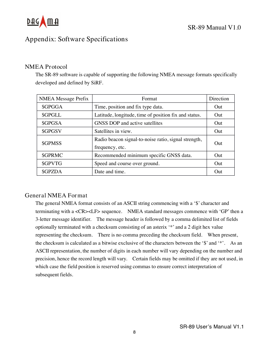
Appendix: Software Specifications
SR-89 Manual V1.0
NMEA Protocol
The SR-89 software is capable of supporting the following NMEA message formats specifically
developed and defined by SiRF.
NMEA Message Prefix
$GPGGA
$GPGLL
$GPGSA
$GPGSV
$GPMSS
$GPRMC
$GPVTG
$GPZDA
Format
Direction
Time, position and fix type data.
Latitude, longitude, time of position fix and status.
GNSS DOP and active satellites
Satellites in view.
Radio beacon signal-to-noise ratio, signal strength,
frequency, etc.
Recommended minimum specific GNSS data.
Speed and course over ground.
Date and time.
Out
Out
Out
Out
Out
Out
Out
Out
General NMEA Format
The general NMEA format consists of an ASCII string commencing with a ‘$’ character and
terminating with a sequence. NMEA standard messages commence with ‘GP’ then a
3-letter message identifier. The message header is followed by a comma delimited list of fields
optionally terminated with a checksum consisting of an asterix ‘*’ and a 2 digit hex value
representing the checksum. There is no comma preceding the checksum field. When present,
the checksum is calculated as a bitwise exclusive of the characters between the ‘$’ and ‘*’. As an
ASCII representation, the number of digits in each number will vary depending on the number and
precision, hence the record length will vary. Certain fields may be omitted if they are not used, in
which case the field position is reserved using commas to ensure correct interpretation of
subsequent fields.
8
SR-89 User’s Manual V1.1
�


 2023年江西萍乡中考道德与法治真题及答案.doc
 2012年重庆南川中考生物真题及答案.doc
 2013年江西师范大学地理学综合及文艺理论基础考研真题.doc
 2020年四川甘孜小升初语文真题及答案I卷.doc
 2020年注册岩土工程师专业基础考试真题及答案.doc
 2023-2024学年福建省厦门市九年级上学期数学月考试题及答案.doc
 2021-2022学年辽宁省沈阳市大东区九年级上学期语文期末试题及答案.doc
 2022-2023学年北京东城区初三第一学期物理期末试卷及答案.doc
 2018上半年江西教师资格初中地理学科知识与教学能力真题及答案.doc
 2012年河北国家公务员申论考试真题及答案-省级.doc
 2020-2021学年江苏省扬州市江都区邵樊片九年级上学期数学第一次质量检测试题及答案.doc
 2022下半年黑龙江教师资格证中学综合素质真题及答案.doc