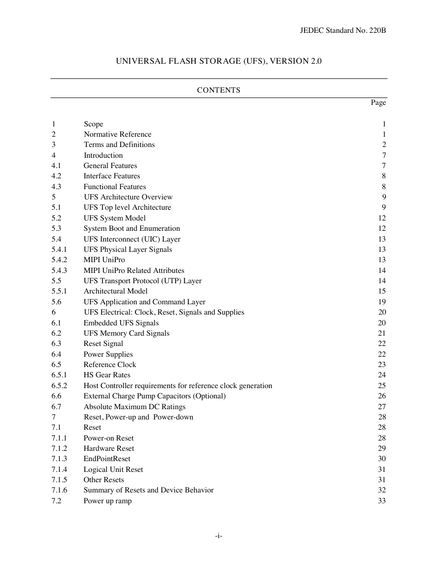
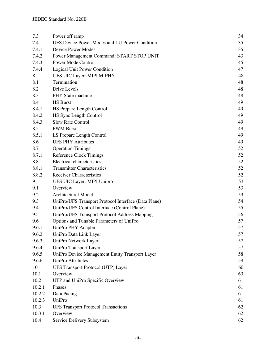
Contents
Figures
Tables
1 Scope
2 Normative Reference
3 Terms and Definitions
3.1 Acronyms
3.2 Terms and Definitions
3.3 Keywords
3.4 Abbreviations
3.5 Conventions
4 Introduction
4.1 General Features
4.2 Interface Features
4.3 Functional Features
5 UFS Architecture Overview
5.1 UFS Top level Architecture
Application Layer
UFS Device Manager
5.1 UFS Top level Architecture (cont’d)
Service Access Points
5.1 UFS Top level Architecture (cont’d)
UIO_SAP
UDM_SAP
UFS Transport Protocol Layer
UFS Interconnect Layer
UFS Topology
5.2 UFS System Model
5.3 System Boot and Enumeration
5.4 UFS Interconnect (UIC) Layer
5.4.1 UFS Physical Layer Signals
5.4.2 MIPI UniPro
5.4.3 MIPI UniPro Related Attributes
5.5 UFS Transport Protocol (UTP) Layer
5.5.1 Architectural Model
5.5.1.1 Client-Server Model
5.5.1.2 CDB, Status, Task Management
5.5.1.3 Nexus
5.5.1.4 SCSI Command Model
5.5.1.5 SCSI Task Management Functions
5.6 UFS Application and Command Layer
6 UFS Electrical: Clock, Reset, Signals and Supplies
6.1 Embedded UFS Signals
6.2 UFS Memory Card Signals
6.3 Reset Signal
6.4 Power Supplies
6.5 Reference Clock
6.5.1 HS Gear Rates
6.5.2 Host Controller requirements for reference clock generation
6.6 External Charge Pump Capacitors (Optional)
6.7 Absolute Maximum DC Ratings
7 Reset, Power-up and Power-down
7.1 Reset
7.1.1 Power-on Reset
7.1.2 Hardware Reset
7.1.3 EndPointReset
7.1.4 Logical Unit Reset
7.1.5 Other Resets
7.1.6 Summary of Resets and Device Behavior
7.2 Power up ramp
7.3 Power off ramp
7.4 UFS Device Power Modes and LU Power Condition
7.4.1 Device Power Modes
7.4.1.1 Active Power Mode
7.4.1.1 Active Power Mode (cont’d)
7.4.1.2 Idle Power Mode
7.4.1.3 Pre-Active Power Mode
7.4.1.4 UFS-Sleep Power Mode
7.4.1.5 Pre-Sleep Power Mode
7.4.1.6 UFS-PowerDown Power Mode
7.4.1.7 Pre-PowerDown Power Mode
7.4.1.8 Power Mode State Machine
7.4.1.8.1 Transitions from Powered On Power Mode
7.4.1.8.2 Transitions from Pre‐Active Power Mode
7.4.1.8.3 Transitions from Active Power Mode
7.4.1.8.4 Transitions from Idle Power Mode
7.4.1.8.5 Transitions from Pre‐Sleep Power Mode
7.4.1.8.6 Transitions from UFS‐Sleep Power Mode
7.4.1.8.7 Transitions from Pre‐PowerDown Power Mode
7.4.1.8.8 Transitions from UFS‐PowerDown Power Mode
7.4.1.8.9 SCSI command and UPIU transactions
7.4.1.9 Device Well Know Logical Unit Responses to SCSI commands
7.4.1.9 Device Well Know Logical Unit Responses to SCSI commands (cont’d)
7.4.2 Power Management Command: START STOP UNIT
7.4.3 Power Mode Control
7.4.4 Logical Unit Power Condition
8 UFS UIC Layer: MIPI M-PHY
8.1 Termination
8.2 Drive Levels
8.3 PHY State machine
8.4 HS Burst
8.4.1 HS Prepare Length Control
8.4.2 HS Sync Length Control
8.4.3 Slew Rate Control
8.5 PWM Burst
8.5.1 LS Prepare Length Control
8.6 UFS PHY Attributes
8.7 Operation Timings
8.7.1 Reference Clock Timings
8.8 Electrical characteristics
8.8.1 Transmitter Characteristics
8.8.2 Receiver Characteristics
9 UFS UIC Layer: MIPI Unipro
9.1 Overview
9.2 Architectural Model
9.3 UniPro/UFS Transport Protocol Interface (Data Plane)
9.4 UniPro/UFS Control Interface (Control Plane)
9.5 UniPro/UFS Transport Protocol Address Mapping
9.6 Options and Tunable Parameters of UniPro
9.6.1 UniPro PHY Adapter
9.6.2 UniPro Data Link Layer
9.6.3 UniPro Network Layer
9.6.4 UniPro Transport Layer
9.6.5 UniPro Device Management Entity Transport Layer
9.6.6 UniPro Attributes
10 UFS Transport Protocol (UTP) Layer
10.1 Overview
10.2 UTP and UniPro Specific Overview
10.2.1 Phases
10.2.2 Data Pacing
10.2.3 UniPro
10.3 UFS Transport Protocol Transactions
10.3.1 Overview
10.4 Service Delivery Subsystem
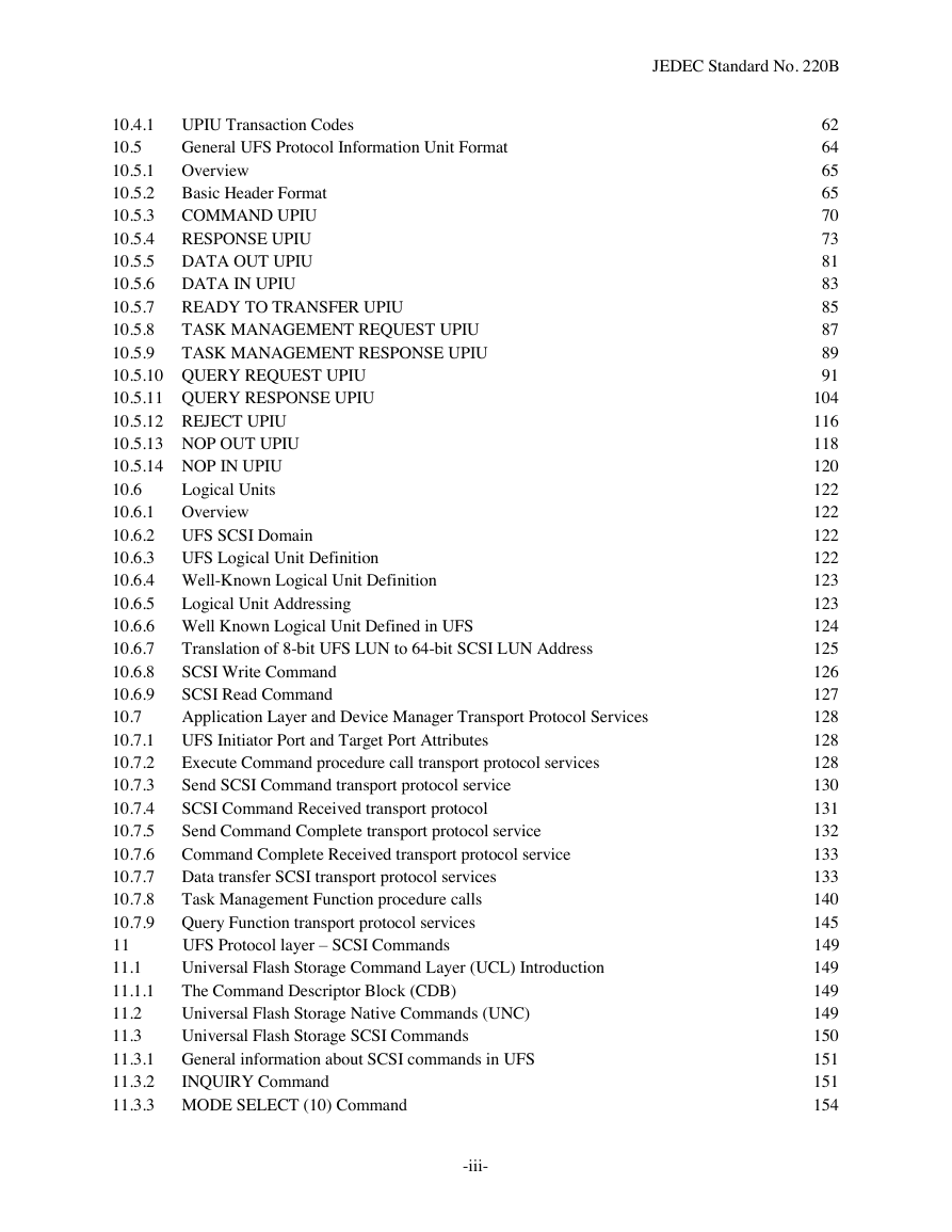
10.4.1 UPIU Transaction Codes
10.5 General UFS Protocol Information Unit Format
10.5.1 Overview
10.5.2 Basic Header Format
10.5.3 COMMAND UPIU
10.5.3.1 Overview
10.5.3.2 Basic Header
10.5.4 RESPONSE UPIU
10.5.4.1 Overview
10.5.4.2 Basic Header
10.5.5 DATA OUT UPIU
10.5.5.1 Overview
10.5.5.2 Basic Header
10.5.6 DATA IN UPIU
10.5.6.1 Overview
10.5.6.2 Basic Header
10.5.7 READY TO TRANSFER UPIU
10.5.7.1 Overview
10.5.7.2 Basic Header
10.5.8 TASK MANAGEMENT REQUEST UPIU
10.5.8.1 Overview
10.5.8.2 Basic Header
10.5.9 TASK MANAGEMENT RESPONSE UPIU
10.5.9.1 Overview
10.5.9.2 Basic Header
10.5.10 QUERY REQUEST UPIU
10.5.10.1 Overview
10.5.10.2 Query Function
10.5.10.3 Transaction Specific Fields
10.5.10.4 Read Descriptor Opcode
10.5.10.5 Write Descriptor Opcode
10.5.10.6 Read Attribute Opcode
10.5.10.7 Write Attribute Opcode
10.5.10.8 Read Flag Opcode
10.5.10.9 Set Flag
10.5.10.10 Clear Flag
10.5.10.11 Toggle Flag
10.5.10.12 NOP
10.5.11 QUERY RESPONSE UPIU
10.5.11.1 Overview
10.5.11.2 Query Function
10.5.11.3 Query Response
10.5.11.4 Device Information
10.5.11.5 Transaction Specific Fields
10.5.11.6 Read Descriptor Opcode
10.5.11.7 Write Descriptor Opcode
10.5.11.8 Read Attribute Opcode
10.5.11.9 Write Attribute Opcode
10.5.11.10 Read Flag Opcode
10.5.11.11 Set Flag
10.5.11.12 Clear Flag
10.5.11.13 Toggle Flag
10.5.11.14 NOP
10.5.12 REJECT UPIU
10.5.12.1 Overview
10.5.12.2 Basic Header
10.5.13 NOP OUT UPIU
10.5.13.1 Overview
10.5.13.2 Basic Header
10.5.14 NOP IN UPIU
10.5.14.1 Overview
10.5.14.2 Basic Header
10.6 Logical Units
10.6.1 Overview
10.6.2 UFS SCSI Domain
10.6.3 UFS Logical Unit Definition
10.6.4 Well-Known Logical Unit Definition
10.6.5 Logical Unit Addressing
10.6.6 Well Known Logical Unit Defined in UFS
10.6.7 Translation of 8-bit UFS LUN to 64-bit SCSI LUN Address
10.6.8 SCSI Write Command
10.6.9 SCSI Read Command
10.7 Application Layer and Device Manager Transport Protocol Services
10.7.1 UFS Initiator Port and Target Port Attributes
10.7.2 Execute Command procedure call transport protocol services
10.7.3 Send SCSI Command transport protocol service
10.7.4 SCSI Command Received transport protocol
10.7.5 Send Command Complete transport protocol service
10.7.6 Command Complete Received transport protocol service
10.7.7 Data transfer SCSI transport protocol services
10.7.7.1 Send Data-In transport protocol service
10.7.7.2 Data-In Delivered transport protocol service
10.7.7.3 Receive Data-Out transport protocol service
10.7.7.4 Data-Out Received transport protocol service
10.7.8 Task Management Function procedure calls
10.7.8.1 ABORT TASK
10.7.8.2 ABORT TASK SET
10.7.8.3 CLEAR TASK SET
10.7.8.4 LOGICAL UNIT RESET
10.7.8.5 QUERY TASK
10.7.8.6 QUERY TASK SET
10.7.8.7 Task Management SCSI Transport Protocol Services
10.7.8.8 Send Task Management Request SCSI transport protocol service request
10.7.8.9 Task Management Request Received SCSI transport protocol service indication
10.7.8.10 Task Management Function Executed SCSI transport protocol service response
10.7.8.11 Received Task Management Function Executed SCSI transport protocol service confirmation
10.7.9 Query Function transport protocol services
10.7.9.1 Send Query Request UFS transport protocol service
10.7.9.2 Query Request Received UFS transport protocol service indication
10.7.9.3 Query Function Executed UFS transport protocol service response
10.7.9.4 Received Query Function Executed UFS transport protocol service confirmation
11 UFS Protocol layer – SCSI Commands
11.1 Universal Flash Storage Command Layer (UCL) Introduction
11.1.1 The Command Descriptor Block (CDB)
11.1.1.1 Operation code
11.2 Universal Flash Storage Native Commands (UNC)
11.3 Universal Flash Storage SCSI Commands
11.3.1 General information about SCSI commands in UFS
11.3.2 INQUIRY Command
11.3.2.1 VITAL PRODUCT DATA
11.3.2.2 STANDARD INQUIRY DATA
11.3.2.3 Inquiry Command Data Response
11.3.2.4 Inquiry Response Data
11.3.2.5 Inquiry Command Status Response
11.3.3 MODE SELECT (10) Command
11.3.3.1 Mode Select Command Parameters
11.3.3.2 Mode Select Command Data Transfer
11.3.3.3 Mode Select Command Status Response
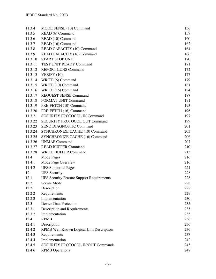
11.3.4 MODE SENSE (10) Command
11.3.4.1 Mode Sense Command Parameters
11.3.4.2 Page Control Function
11.3.4.3 Mode Sense Command Data Transfer
11.3.4.4 Mode Sense Command Status Response
11.3.5 READ (6) Command
11.3.5.1 Read (6) Command Parameters
11.3.5.2 Read (6) Command Data Transfer
11.3.5.3 Read (6) Command Status Response
11.3.6 READ (10) Command
11.3.6.1 Read (10) Command Parameters
11.3.6.2 Read (10) Command Data Transfer
11.3.6.3 Read (10) Command Status Response
11.3.7 READ (16) Command
11.3.7.1 Read (16) Command Parameters
11.3.7.2 Read (16) Command Data Transfer
11.3.7.3 Read (16) Command Status Response
11.3.8 READ CAPACITY (10) Command
11.3.8.1 Read Capacity (10) Data Response
11.3.8.2 Read Capacity (10) Parameter Data
11.3.8.3 Read Capacity (10) Status Response
11.3.9 READ CAPACITY (16) Command
11.3.9.1 Read Capacity (16) Data Response
11.3.9.2 Read Capacity (16) Parameter Data
11.3.9.3 Read Capacity (16) Status Response
11.3.10 START STOP UNIT
11.3.10.1 START STOP UNIT Parameters
11.3.10.2 Start Stop Unit Data Response
11.3.10.3 Start Stop Unit Status Response
11.3.11 TEST UNIT READY Command
11.3.11.1 Test Unit Ready Data Response
11.3.11.2 Test Unit Ready Status Response
11.3.12 REPORT LUNS Command
11.3.12.1 Report LUNS Command Parameters
11.3.12.2 Report LUNS Command Select Report Field Values
11.3.12.3 Report LUNS Data Response
11.3.12.4 Report LUNS Parameter Data Format
11.3.12.5 Report LUNS LUN Addressing Formats
11.3.12.6 Report LUNS Status Response
11.3.12.7 UFS LUN Format
11.3.13 VERIFY (10)
11.3.13.1 Verify Command Parameters
11.3.13.2 Verify Command Data Transfer
11.3.13.3 Verify Command Status Response
11.3.14 WRITE (6) Command
11.3.14.1 Write (6) Command Parameters
11.3.14.2 Write (6) Command Data Transfer
11.3.14.3 Write (6) Command Status Response
11.3.15 WRITE (10) Command
11.3.15.1 Write (10) Command Parameters
11.3.15.2 Write(10) Command Data Transfer
11.3.15.3 Write (10) Command Status Response
11.3.16 WRITE (16) Command
11.3.16.1 Write (16) Command Parameters
11.3.16.2 Write (16) Command Data Transfer
11.3.16.3 Write (16) Command Status Response
11.3.17 REQUEST SENSE Command
11.3.17.1 Request Sense Data Response
11.3.17.2 Sense Data
11.3.17.3 Sense Key Descriptions
11.3.17.4 ASC and ASCQ
11.3.17.5 Request Sense Status Response
11.3.18 FORMAT UNIT Command
11.3.18.1 Format Unit Command Parameters
11.3.18.2 Format Unit Command Data Transfer
11.3.18.3 Format Unit Command Status Response
11.3.19 PRE-FETCH (10) Command
11.3.19.1 PRE-FETCH (10) Command Parameters
11.3.19.2 PRE-FETCH Command Data Transfer
11.3.19.3 PRE-FETCH Command Status Response
11.3.20 PRE-FETCH (16) Command
11.3.21 SECURITY PROTOCOL IN Command
11.3.21.1 SECURITY PROTOCOL IN Command Parameter
11.3.21.2 SECURITY PROTOCOL IN Command Data Transfer
11.3.21.3 SECURITY PROTOCOL IN Command Status Response
11.3.22 SECURITY PROTOCOL OUT Command
11.3.22.1 SECURITY PROTOCOL OUT Command Parameter
11.3.22.2 SECURITY PROTOCOL OUT Command Data Transfer
11.3.22.3 SECURITY PROTOCOL OUT Command Status Response
11.3.23 SEND DIAGNOSTIC Command
11.3.23.1 Send Diagnostic Parameters
11.3.23.2 Send Diagnostic Command Data Transfer
11.3.23.3 Send Diagnostic Command Status Response
11.3.24 SYNCHRONIZE CACHE (10) Command
11.3.24.1 Synchronize Cache Command Parameters
11.3.24.2 Synchronize Cache Command Data Transfer
11.3.24.3 Synchronize Cache Command Status Response
11.3.25 SYNCHRONIZE CACHE (16) Command
11.3.26 UNMAP Command
11.3.26.1 UNMAP parameter list
11.3.26.2 UNMAP block descriptor
11.3.27 READ BUFFER Command
11.3.27.1 Read Buffer Command Parameters
11.3.27.2 Read Buffer Command Mode Field Values
11.3.27.3 Read Buffer Command Data Transfer
11.3.27.4 Read Buffer Command Status Response
11.3.28 WRITE BUFFER Command
11.3.28.1 Write Buffer Command Parameters
11.3.28.2 Write Buffer Command Mode Field Values
11.3.28.3 Write Buffer Command Data Transfer
11.3.28.4 Write Buffer Command Status Response
11.4 Mode Pages
11.4.1 Mode Page Overview
11.4.1.1 Mode Page/Subpage Codes
11.4.1.2 Mode parameter list format
11.4.1.3 Mode Parameter Header
11.4.1.4 Mode Parameter Header Detail
11.4.1.5 Page_0 mode page format
11.4.1.6 Sub_page mode page format
11.4.2 UFS Supported Pages
11.4.2.1 Control Mode Page
11.4.2.2 Control Mode Page Parameters
11.4.2.3 Read-Write Error Recovery Mode Page
11.4.2.4 Read-Write Error Recovery Parameters
11.4.2.5 Caching Mode Page
11.4.2.6 Caching Mode Page Parameters
12 UFS Security
12.1 UFS Security Feature Support Requirements
12.2 Secure Mode
12.2.1 Description
12.2.2 Requirements
12.2.2.1 Secure Removal
12.2.2.2 Erase Operation
12.2.2.3 Discard Operation
12.2.2.4 Purge Operation
12.2.3 Implementation
12.2.3.1 Erase
12.2.3.2 Discard
12.2.3.3 Purge operation
12.2.3.4 Wipe Device
12.2.3.5 bProvisioningType Parameter
12.2.3.6 bSecureRemovalType Parameter
12.3 Device Data Protection
12.3.1 Description and Requirements
12.3.2 Implementation
12.4 RPMB
12.4.1 Description
12.4.2 RPMB Well Known Logical Unit Description
12.4.3 Requirements
12.4.3.1 Memory Map of RPMB LU
12.4.3.2 Algorithm and Key for MAC Calculation
12.4.3.3 RPMB Message Components
12.4.3.4 Messages from Host to Device
12.4.3.5 Messages from Device to Host
12.4.3.6 RPMB Operation Result
12.4.4 Implementation
12.4.4.1 Data Frame for RPMB Message
12.4.4.2 MAC Calculation
12.4.4.3 RPMB Message Data Frame Delivery
12.4.5 SECURITY PROTOCOL IN/OUT Commands
12.4.5.1 CDB format of SECURITY PROTOCOL IN/OUT Commands
12.4.5.2 Security Protocol Information Description
12.4.5.3 Supported security protocols list description
12.4.5.4 Certificate data description
12.4.6 RPMB Operations
12.4.6.1 Request Type Message Delivery
12.4.6.2 Response Type Message Delivery
12.4.6.3 Authentication Key Programming
12.4.6.4 Read Counter Value
12.4.6.5 Authenticated Data Write
12.4.6.6 Authenticated Data Read
12.5 Malware Protection
12.6 Mechanical
13 UFS FUNCTIONAL DESCRIPTIONS
13.1 UFS Boot
13.1.1 Introduction
13.1.2 Boot Configuration
13.1.3 Initialization and boot code download process
13.1.3.1 Partial initialization
13.1.3.2 Boot transfer
13.1.3.3 Initialization completion
13.1.4 Initialization process without boot code download
13.1.5 Boot Logical Unit Operations
13.1.6 Configurability
13.1.7 Security
13.1.7.1 Boot Area Protection
13.2 Logical Unit Management
13.2.1 Introduction
13.2.2 Logical Unit features
13.2.3 Logical Unit Configuration
13.3 Logical Block Provisioning
13.4 Host Device Interaction
13.4.1 Overview
13.4.2 Applicable Devices
13.4.3 Command Queue: Inter-LU Priority
13.4.3.1 Implementation
13.4.4 Background Operations Mode
13.4.4.1 Introduction
13.4.4.2 Purpose
Performance Improvement
13.4.4.3 Background Operations Status
13.4.4.4 Operation Initiation
13.4.4.5 Power Failure
13.4.4.6 Implementation
13.4.5 Power Off Notification
13.4.6 Dynamic Device Capacity
13.4.6.1 Implementation
13.4.6.1.1 Initial Device Requirements
13.4.6.1.2 Dynamic Capacity Procedural Flow
13.4.6.1.3 Dynamic Device Capacity Notification
13.4.6.1.4 Error handling
13.4.6.1.5 Physical Memory Resource State Machine
13.4.7 Data Reliability
13.4.7.1 Description
13.4.7.2 Implementation
13.4.8 Real-Time Clock Information
13.4.9 Context Management
13.4.9.1 Context configuration
13.4.9.2 Activation and direction mode
13.4.9.3 Large-Unit mode
13.4.9.4 Reliability mode
13.4.9.5 Large-Unit Multiplier
13.4.10 System Data Tag Mechanism
13.4.11 Exception Events Mechanism
13.4.12 Data transfer rules related with RTT (Ready-to-Transfer)
13.4.12.1 Implementation
13.5 UFS Cache
14 UFS Descriptors, Flags and Attributes
14.1 UFS Descriptors
14.1.1 Descriptor Types
14.1.2 Descriptor Indexing
14.1.3 Accessing Descriptors
14.1.4 Read Descriptor
14.1.5 Write Descriptor
14.1.6 Descriptor Page Definitions
14.1.6.1 Generic Descriptor Format
14.1.6.2 Device Descriptor
14.1.6.3 Configuration Descriptor
14.1.6.4 Geometry Descriptor
14.1.6.5 Unit Descriptor
14.1.6.6 RPMB Unit Descriptor
14.1.6.7 Power Parameters Descriptor
14.1.6.8 Interconnect Descriptor
14.1.6.9 Manufacturer Name String Descriptor
14.1.6.10 Product Name String Descriptor
14.1.6.11 OEM ID String Descriptor
14.1.6.12 Serial Number String Descriptor
14.2 Flags
14.3 Attributes
Annex A - DYNAMIC CAPACITY HOST IMPLEMENTATION EXAMPLE (informative)
A.1 Overview
A.2 Method Outline
Annex B (informative) Differences between JESD220B and JESD220A
B.1 Changes between JESD220B and its predecessor JESD220A
B.1.1 New features or new definitions
B.1.2 Changes in section 2 “Normative Reference”
B.1.3 Changes in features already defined in UFS 1.1
Standard Improvement Form JEDEC




 2023年江西萍乡中考道德与法治真题及答案.doc
 2012年重庆南川中考生物真题及答案.doc
 2013年江西师范大学地理学综合及文艺理论基础考研真题.doc
 2020年四川甘孜小升初语文真题及答案I卷.doc
 2020年注册岩土工程师专业基础考试真题及答案.doc
 2023-2024学年福建省厦门市九年级上学期数学月考试题及答案.doc
 2021-2022学年辽宁省沈阳市大东区九年级上学期语文期末试题及答案.doc
 2022-2023学年北京东城区初三第一学期物理期末试卷及答案.doc
 2018上半年江西教师资格初中地理学科知识与教学能力真题及答案.doc
 2012年河北国家公务员申论考试真题及答案-省级.doc
 2020-2021学年江苏省扬州市江都区邵樊片九年级上学期数学第一次质量检测试题及答案.doc
 2022下半年黑龙江教师资格证中学综合素质真题及答案.doc