logo资料库

IEC-61851-2017.pdf

第1页 / 共141页
第2页 / 共141页
第3页 / 共141页
第4页 / 共141页
第5页 / 共141页
第6页 / 共141页
第7页 / 共141页
第8页 / 共141页
资料共141页,剩余部分请下载后查看
English
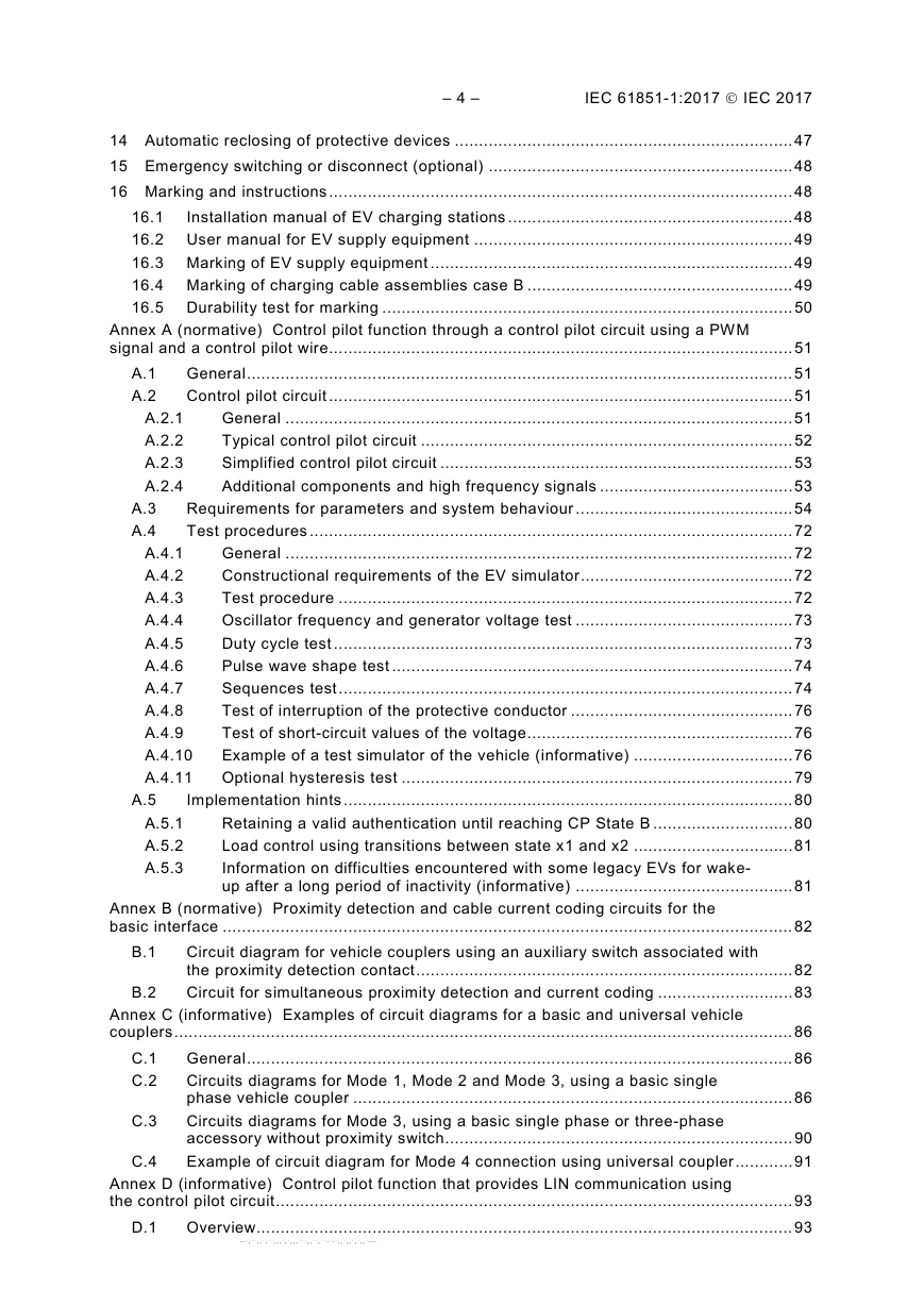
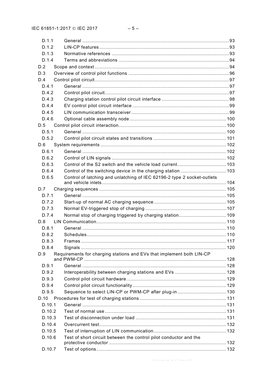
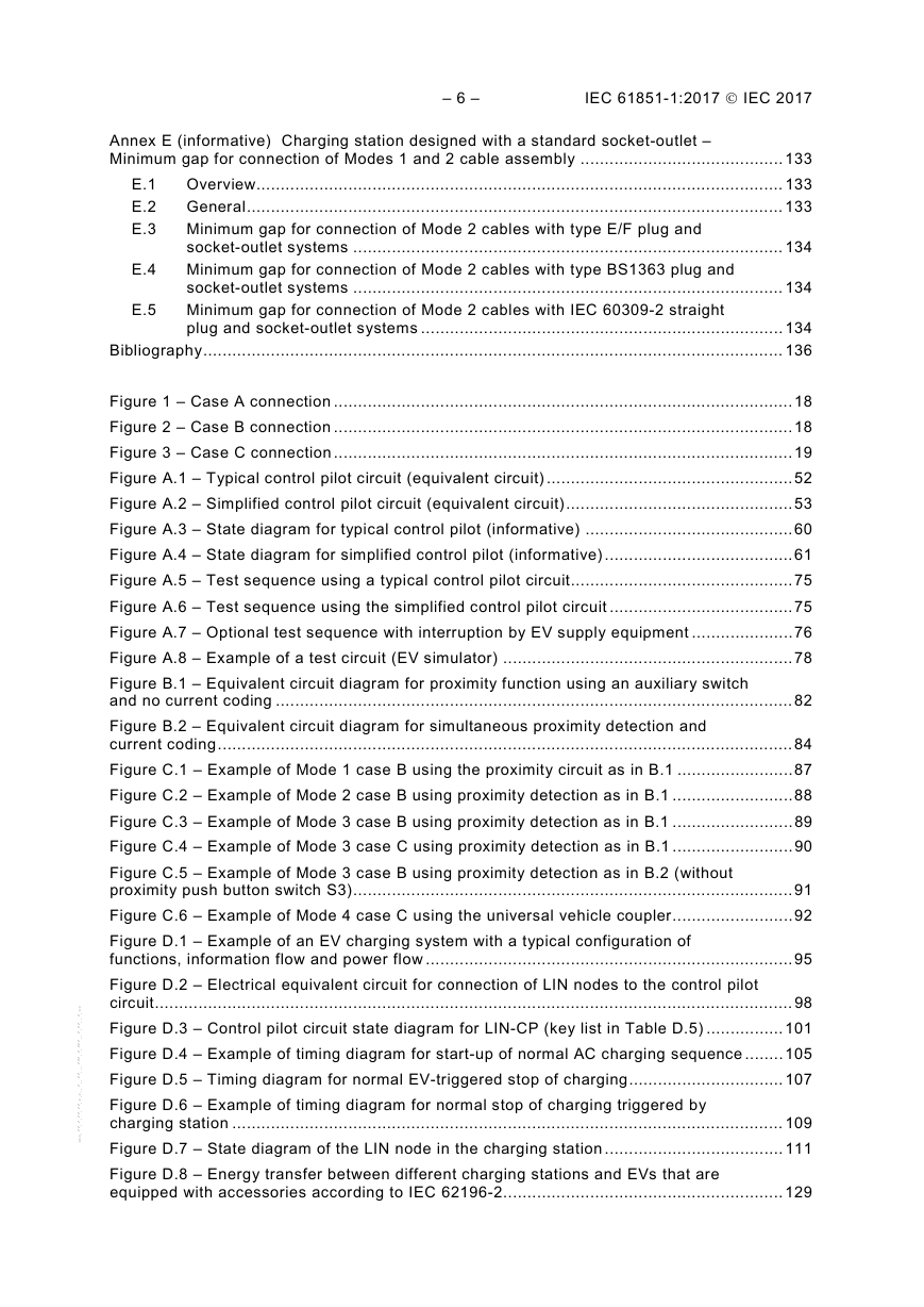
CONTENTS
FOREWORD
INTRODUCTION
1 Scope
2 Normative references
3 Terms and definitions
3.1 Electric supply equipment
3.2 Insulation
3.3 Functions
3.4 Vehicle
3.5 Cords, cables and connection means
3.6 Service and usage
3.7 General terms
4 General requirements
5 Classification
5.1 Characteristics of power supply and output
5.1.1 Characteristics of power supply input
5.1.2 Characteristics of power supply output
5.2 Normal environmental conditions
5.3 Special environmental conditions
5.4 Access
5.5 Mounting method
5.6 Protection against electric shock
5.7 Charging modes
6 Charging modes and functions
6.1 General
6.2 Charging modes
6.2.1 Mode 1
6.2.2 Mode 2
6.2.3 Mode 3
6.2.4 Mode 4
6.3 Functions provided in Mode 2, 3 and 4
6.3.1 Mandatory functions in Modes 2, 3, and 4
6.3.2 Optional functions for Modes 2, 3 and 4
7 Communications
7.1 Digital communication between the EV supply equipment and the EV
7.2 Digital communication between the EV supply equipment and the management system
8 Protection against electric shock
8.1 Degrees of protection against access to hazardous-live-parts
8.2 Stored energy
8.2.1 Disconnection of plug connected EV supply equipment
8.2.2 Loss of supply voltage to permanently connected EV supply equipment
8.3 Fault protection
8.4 Protective conductor
8.5 Residual current protective devices
8.6 Safety requirements for signalling circuits between the EV supply equipment and the EV
8.7 Isolating transformers
9 Conductive electrical interface requirements
9.1 General
9.2 Functional description of standard accessories
9.3 Functional description of the basic interface
9.4 Functional description of the universal interface
9.5 Functional description of the DC interface
9.6 Functional description of the combined interface
9.7 Wiring of the neutral conductor
10 Requirements for adaptors
11 Cable assembly requirements
11.1 General
11.2 Electrical rating
11.3 Dielectric withstand characteristics
11.4 Construction requirements
11.5 Cable dimensions
11.6 Strain relief
11.7 Cable management and storage means for cables assemblies
12 EV supply equipment constructional requirements and tests
12.1 General
12.2 Characteristics of mechanical switching devices
12.2.1 General
12.2.2 Switch and switch-disconnector
12.2.3 Contactor
12.2.4 Circuit-breaker
12.2.5 Relays
12.2.6 Inrush current
12.2.7 Residual direct current monitoring device (RDC MD)
12.3 Clearances and creepage distances
12.4 IP degrees
12.4.1 Degrees of protection against solid foreign objects and water for the enclosures
12.4.2 Degrees of protection against solid foreign objects and water for basic, universal and combined and DC interfaces
12.5 Insulation resistance
12.6 Touch current
12.7 Dielectric withstand voltage
12.7.1 AC withstand voltage
12.7.2 Impulse dielectric withstand (1,2 μs/50 μs)
12.8 Temperature rise
12.9 Damp heat functional test
12.10 Minimum temperature functional test
12.11 Mechanical strength
13 Overload and short-circuit protection
13.1 General
13.2 Overload protection of the cable assembly
13.3 Short-circuit protection of the charging cable
14 Automatic reclosing of protective devices
15 Emergency switching or disconnect (optional)
16 Marking and instructions
16.1 Installation manual of EV charging stations
16.2 User manual for EV supply equipment
16.3 Marking of EV supply equipment
16.4 Marking of charging cable assemblies case B
16.5 Durability test for marking
Annexes
Annex A (normative) Control pilot function through a control pilot circuit using a PWM signal and a control pilot wire
A.1 General
A.2 Control pilot circuit
A.2.1 General
A.2.2 Typical control pilot circuit
A.2.3 Simplified control pilot circuit
A.2.4 Additional components and high frequency signals
A.3 Requirements for parameters and system behaviour
A.4 Test procedures
A.4.1 General
A.4.2 Constructional requirements of the EV simulator
A.4.3 Test procedure
A.4.4 Oscillator frequency and generator voltage test
A.4.5 Duty cycle test
A.4.6 Pulse wave shape test
A.4.7 Sequences test
A.4.8 Test of interruption of the protective conductor
A.4.9 Test of short-circuit values of the voltage
A.4.10 Example of a test simulator of the vehicle (informative)
A.4.11 Optional hysteresis test
A.5 Implementation hints
A.5.1 Retaining a valid authentication until reaching CP State B
A.5.2 Load control using transitions between state x1 and x2
A.5.3 Information on difficulties encountered with some legacy EVs for wake-up after a long period of inactivity (informative)
Annex B (normative) Proximity detection and cable current coding circuits for the basic interface
B.1 Circuit diagram for vehicle couplers using an auxiliary switch associated with the proximity detection contact
B.2 Circuit for simultaneous proximity detection and current coding
Annex C (informative) Examples of circuit diagrams for a basic and universal vehicle couplers
C.1 General
C.2 Circuits diagrams for Mode 1, Mode 2 and Mode 3, using a basic single phase vehicle coupler
C.3 Circuits diagrams for Mode 3, using a basic single phase or three-phase accessory without proximity switch
C.4 Example of circuit diagram for Mode 4 connection using universal coupler
Annex D (informative) Control pilot function that provides LIN communicationusing the control pilot circuit
D.1 Overview
D.1.1 General
D.1.2 LIN-CP features
D.1.3 Normative references
D.1.4 Terms and abbreviations
D.2 Scope and context
D.3 Overview of control pilot functions
D.4 Control pilot circuit
D.4.1 General
D.4.2 Control pilot circuit
D.4.3 Charging station control pilot circuit interface
D.4.4 EV control pilot circuit interface
D.4.5 LIN communication transceiver
D.4.6 Optional cable assembly node
D.5 Control pilot circuit interaction
D.5.1 General
D.5.2 Control pilot circuit states and transitions
D.6 System requirements
D.6.1 General
D.6.2 Control of LIN signals
D.6.3 Control of the S2 switch and the vehicle load current
D.6.4 Control of the switching device in the charging station
D.6.5 Control of latching and unlatching of IEC€62196-2 type 2 socket-outlets and vehicle inlets
D.7 Charging sequences
D.7.1 General
D.7.2 Start-up of normal AC charging sequence
D.7.3 Normal EV-triggered stop of charging
D.7.4 Normal stop of charging triggered by charging station
D.8 LIN Communication
D.8.1 General
D.8.2 Schedules
D.8.3 Frames
D.8.4 Signals
D.9 Requirements for charging stations and EVs that implement both LIN-CP and PWM-CP
D.9.1 General
D.9.2 Interoperability between charging stations and EVs
D.9.3 Control pilot circuit hardware
D.9.4 Control pilot circuit functionality
D.9.5 Sequence to select LIN-CP or PWM-CP after plug-in
D.10 Procedures for test of charging stations
D.10.1 General
D.10.2 Test of normal use
D.10.3 Test of disconnection under load
D.10.4 Overcurrent test
D.10.5 Test of interruption of LIN communication
D.10.6 Test of short circuit between the control pilot conductor and the protective conductor
D.10.7 Test of options
Annex E (informative) Charging station designed with a standard socket-outlet – Minimum gap for connection of Modes 1 and 2 cable assembly
E.1 Overview
E.2 General
E.3 Minimum gap for connection of Mode 2 cables with type E/F plug and socket-outlet systems
E.4 Minimum gap for connection of Mode 2 cables with type BS1363 plug and socket-outlet systems
E.5 Minimum gap for connection of Mode 2 cables with IEC€60309-2 straight plug and socket-outlet systems
Bibliography
Figures
Figure 1 – Case A connection
Figure 2 – Case B connection
Figure 3 – Case C connection
Figure A.1 – Typical control pilot circuit (equivalent circuit)
Figure A.2 – Simplified control pilot circuit (equivalent circuit)
Figure A.3 – State diagram for typical control pilot (informative)
Figure A.4 – State diagram for simplified control pilot (informative)
Figure A.5 – Test sequence using a typical control pilot circuit
Figure A.6 – Test sequence using the simplified control pilot circuit
Figure A.7 – Optional test sequence with interruption by EV supply equipment
Figure A.8 – Example of a test circuit (EV simulator)
Figure B.1 – Equivalent circuit diagram for proximity function using an auxiliary switch and no current coding
Figure B.2 – Equivalent circuit diagram for simultaneous proximity detection and current coding
Figure C.1 – Example of Mode 1 case B using the proximity circuit as in B.1
Figure C.2 – Example of Mode 2 case B using proximity detection as in B.1
Figure C.3 – Example of Mode 3 case B using proximity detection as in B.1
Figure C.4 – Example of Mode 3 case C using proximity detection as in B.1
Figure C.5 – Example of Mode 3 case B using proximity detection as in B.2 (without proximity push button switch S3)
Figure C.6 – Example of Mode 4 case C using the universal vehicle coupler
Figure D.1 – Example of an EV charging system with a typical configuration of functions, information flow and power flow
Figure D.2 – Electrical equivalent circuit for connection of LIN nodes to the control pilot circuit
Figure D.3 – Control pilot circuit state diagram for LIN-CP (key list in Table D.5)
Figure D.4 – Example of timing diagram for start-up of normal AC charging sequence
Figure D.5 – Timing diagram for normal EV-triggered stop of charging
Figure D.6 – Example of timing diagram for normal stopof charging triggered by charging station
Figure D.7 – State diagram of the LIN node in the charging station
Figure D.8 – Energy transfer between different charging stations and EVs that are equipped with accessories according to IEC 62196-2
Figure D.9 – Control pilot circuit state diagram for LIN-CP and PWM-CP (See key list in Table D.5)
Figure E.1 – Examples of standard plugs that are considered for this Annex E
Figure E.2 – Packaging configurations allowing the use of a large part of the common products for standard plugs and socket-outlets
Tables
Table 1 – Touch current limits
Table A.1 – Maximum allowable high frequency signal voltageson control pilot conductor and the protective conductor
Table A.2 – Control pilot circuit parameters and values for the EV supply equipment
Table A.3 – EV control pilot circuit values and parameters and values for the EV
Table A.4 – System states detected by the EV supply equipment
Table A.5 – State behaviour
Table A.6 – List of sequences
Table A.7 – PWM duty cycle provided by EV supply equipment
Table A.8 – Maximum current to be drawn by vehicle
Table A.9 – Test resistance values
Table A.10 – Parameters of control pilot voltages
Table A.11 – Test parameters of control pilot signals
Table A.12 – Parameters for sequence tests
Table A.13 – Position of switches
Table A.14 – Initial settings of the potentiometer at the beginning of each test
Table B.1 – Component values proximity circuit without current coding
Table B.2 – Current coding resistor for EV plug and vehicle connector
Table C.1 – Component description for Figure C.6 Mode 4 case C
Table D.1 – Control pilot functions in LIN-CP and PWM-CP
Table D.2 – Additional LIN-CP control pilot functions
Table D.3 – Generation and detection of CP voltage levels
Table D.4 – Generation and detection of LIN communication levels
Table D.5 – Key list for Figure D.3 and Figure D.9
Table D.6 – Control of LIN signals
Table D.7 – Control of the S2 switch and the vehicle load
Table D.8 – Control of the switching device
Table D.9 – Control of latching and unlatching
Table D.10 – Timing for start-up of normal charging sequence
Table D.11 – Timing for normal EV-triggered stop of charging
Table D.12 – Timing for normal stop of charging triggered by charging station
Table D.13 – States of the LIN node in the charging station and frame schedule description
Table D.14 – Transitions of the LIN node in the charging station
Table D.15 – Frames for AC charging
Table D.16 – General signals
Table D.17 – Signals for version negotiation
Table D.18 – Signals for system initialization
Table D.19 – Signals for EV status information
Table D.20 – Signals for charging station status information
Table D.21 – Codes for the frame StNotReadyList
Table D.22 – Codes for frame EvS2openList
Table D.23 – Codes for frame StErrorList
Table D.24 – Codes for frame EvErrorList
Table D.25 – Normal charge cycle test
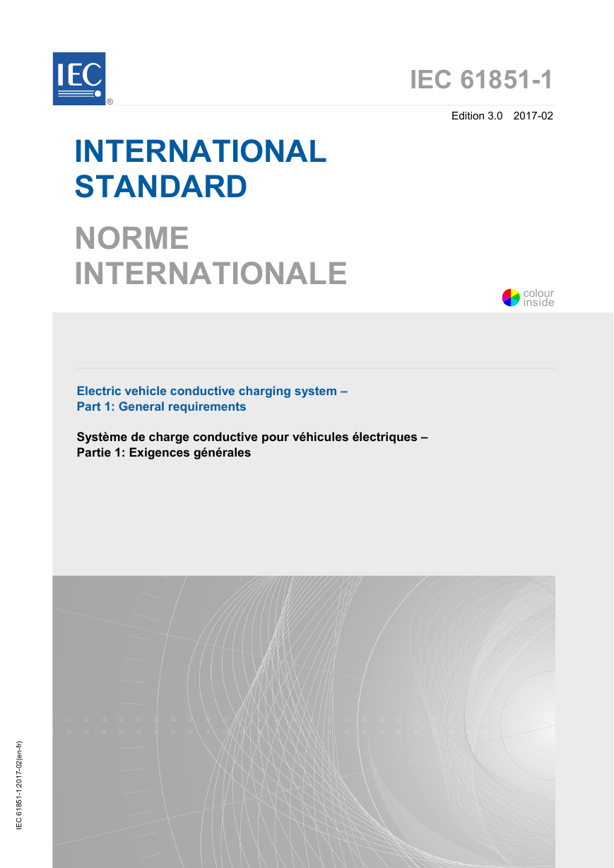
IEC 61851-1 Edition 3.0 2017-02 ® INTERNATIONAL STANDARD NORME INTERNATIONALE Electric vehicle conductive charging system – Part 1: General requirements Système de charge conductive pour véhicules électriques – Partie 1: Exigences générales ) r f - n e ( 2 0 - 7 1 0 2 : 1 - 1 5 8 1 6 C E I colourinside
THIS PUBLICATION IS COPYRIGHT PROTECTED Copyright © 2017 IEC, Geneva, Switzerland All rights reserved. Unless otherwise specified, no part of this publication may be reproduced or utilized in any form or by any means, electronic or mechanical, including photocopying and microfilm, without permission in writing from either IEC or IEC's member National Committee in the country of the requester. If you have any questions about IEC copyright or have an enquiry about obtaining additional rights to this publication, please contact the address below or your local IEC member National Committee for further information. Droits de reproduction réservés. Sauf indication contraire, aucune partie de cette publication ne peut être reproduite ni utilisée sous quelque forme que ce soit et par aucun procédé, électronique ou mécanique, y compris la photocopie et les microfilms, sans l'accord écrit de l'IEC ou du Comité national de l'IEC du pays du demandeur. Si vous avez des questions sur le copyright de l'IEC ou si vous désirez obtenir des droits supplémentaires sur cette publication, utilisez les coordonnées ci-après ou contactez le Comité national de l'IEC de votre pays de résidence. IEC Central Office 3, rue de Varembé CH-1211 Geneva 20 Switzerland Tel.: +41 22 919 02 11 Fax: +41 22 919 03 00 info@iec.ch www.iec.ch for consulting About the IEC The International Electrotechnical Commission (IEC) is the leading global organization that prepares and publishes International Standards for all electrical, electronic and related technologies. About IEC publications The technical content of IEC publications is kept under constant review by the IEC. Please make sure that you have the latest edition, a corrigenda or an amendment might have been published. IEC Catalogue - webstore.iec.ch/catalogue The stand-alone application the entire bibliographical information on IEC International Standards, Technical Specifications, Technical Reports and other documents. Available for PC, Mac OS, Android Tablets and iPad. IEC publications search - www.iec.ch/searchpub The advanced search enables to find IEC publications by a variety of criteria technical committee,…). It also gives information on projects, replaced and withdrawn publications. IEC Just Published - webstore.iec.ch/justpublished Stay up to date on all new IEC publications. Just Published details all new publications released. Available online and also once a month by email. Electropedia - www.electropedia.org The world's leading online dictionary of electronic and electrical terms containing 20 000 terms and definitions in English and French, with equivalent terms in 16 additional languages. Also known as the International Electrotechnical Vocabulary (IEV) online. IEC Glossary - std.iec.ch/glossary 65 000 electrotechnical terminology entries in English and French extracted from the Terms and Definitions clause of IEC publications issued since 2002. Some entries have been collected from earlier publications of IEC TC 37, 77, 86 and CISPR. IEC Customer Service Centre - webstore.iec.ch/csc If you wish to give us your feedback on this publication or need further assistance, please contact the Customer Service Centre: csc@iec.ch. (reference number, text, sur les Normes A propos de l'IEC La Commission Electrotechnique Internationale (IEC) est la première organisation mondiale qui élabore et publie des Normes internationales pour tout ce qui a trait à l'électricité, à l'électronique et aux technologies apparentées. A propos des publications IEC Le contenu technique des publications IEC est constamment revu. Veuillez vous assurer que vous possédez l’édition la plus récente, un corrigendum ou amendement peut avoir été publié. Catalogue IEC - webstore.iec.ch/catalogue Application autonome pour consulter tous les renseignements bibliographiques internationales, Spécifications techniques, Rapports techniques et autres documents de l'IEC. Disponible pour PC, Mac OS, tablettes Android et iPad. Recherche de publications IEC - www.iec.ch/searchpub La recherche avancée permet de trouver des publications IEC en utilisant différents critères (numéro de référence, texte, comité d’études,…). Elle donne aussi des informations sur les projets et les publications remplacées ou retirées. IEC Just Published - webstore.iec.ch/justpublished Restez informé sur les nouvelles publications IEC. Just Published détaille les nouvelles publications parues. Disponible en ligne et aussi une fois par mois par email. Electropedia - www.electropedia.org Le premier dictionnaire en ligne de termes électroniques et électriques. Il contient 20 000 termes et définitions en anglais et en français, ainsi que les termes équivalents dans 16 langues additionnelles. Egalement appelé Vocabulaire Electrotechnique International (IEV) en ligne. Glossaire IEC - std.iec.ch/glossary 65 000 entrées terminologiques électrotechniques, en anglais et en français, extraites des articles Termes et Définitions des publications IEC parues depuis 2002. Plus certaines entrées antérieures extraites des publications des CE 37, 77, 86 et CISPR de l'IEC. Service Clients - webstore.iec.ch/csc Si vous désirez nous donner des commentaires sur cette publication ou si vous avez des questions contactez-nous: csc@iec.ch.
IEC 61851-1 Edition 3.0 2017-02 ® INTERNATIONAL STANDARD NORME INTERNATIONALE Electric vehicle conductive charging system – Part 1: General requirements Système de charge conductive pour véhicules électriques – Partie 1: Exigences générales INTERNATIONAL ELECTROTECHNICAL COMMISSION COMMISSION ELECTROTECHNIQUE INTERNATIONALE ICS 43.120 ISBN 978-2-8322-3766-3 Warning! Make sure that you obtained this publication from an authorized distributor. Attention! Veuillez vous assurer que vous avez obtenu cette publication via un distributeur agréé. ® Registered trademark of the International Electrotechnical Commission Marque déposée de la Commission Electrotechnique Internationale colourinside--`,``,,`,``,,,`,`,,,```,,``,``-`-`,,`,,`,`,,`---
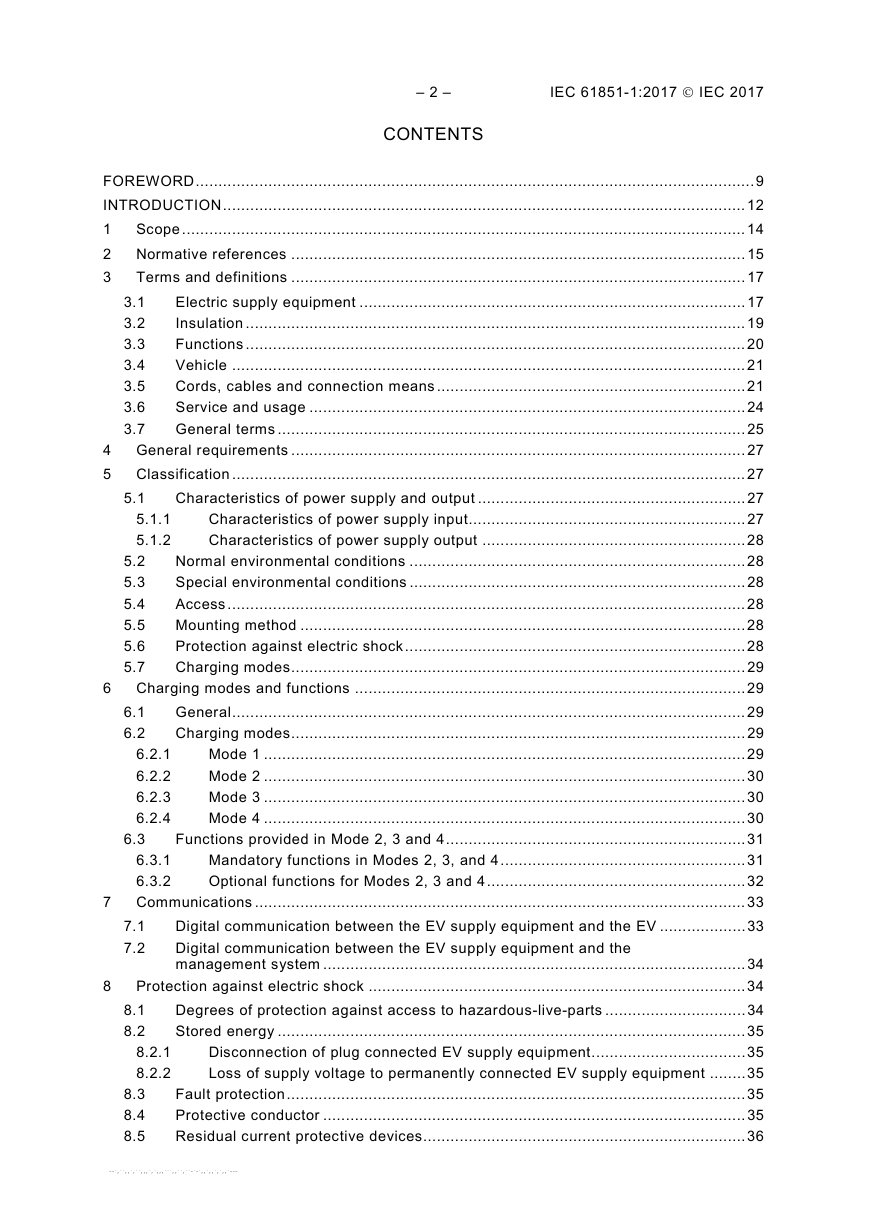
– 2 – IEC 61851-1:2017  IEC 2017 CONTENTS FOREWORD ........................................................................................................................... 9 INTRODUCTION ................................................................................................................... 12 1 Scope ............................................................................................................................ 14 2 Normative references .................................................................................................... 15 3 Terms and definitions .................................................................................................... 17 3.1 Electric supply equipment ..................................................................................... 17 Insulation .............................................................................................................. 19 3.2 3.3 Functions .............................................................................................................. 20 3.4 Vehicle ................................................................................................................. 21 Cords, cables and connection means .................................................................... 21 3.5 3.6 Service and usage ................................................................................................ 24 3.7 General terms ....................................................................................................... 25 4 General requirements .................................................................................................... 27 5 Classification ................................................................................................................. 27 5.1 Characteristics of power supply and output ........................................................... 27 5.1.1 Characteristics of power supply input............................................................. 27 Characteristics of power supply output .......................................................... 28 5.1.2 5.2 Normal environmental conditions .......................................................................... 28 5.3 Special environmental conditions .......................................................................... 28 Access .................................................................................................................. 28 5.4 5.5 Mounting method .................................................................................................. 28 5.6 Protection against electric shock ........................................................................... 28 5.7 Charging modes .................................................................................................... 29 6 Charging modes and functions ...................................................................................... 29 6.1 General ................................................................................................................. 29 6.2 Charging modes .................................................................................................... 29 Mode 1 .......................................................................................................... 29 6.2.1 6.2.2 Mode 2 .......................................................................................................... 30 6.2.3 Mode 3 .......................................................................................................... 30 6.2.4 Mode 4 .......................................................................................................... 30 Functions provided in Mode 2, 3 and 4 .................................................................. 31 6.3 6.3.1 Mandatory functions in Modes 2, 3, and 4 ...................................................... 31 6.3.2 Optional functions for Modes 2, 3 and 4 ......................................................... 32 7 Communications ............................................................................................................ 33 7.1 Digital communication between the EV supply equipment and the EV ................... 33 7.2 management system ............................................................................................. 34 Protection against electric shock ................................................................................... 34 8 8.1 Degrees of protection against access to hazardous-live-parts ............................... 34 8.2 Stored energy ....................................................................................................... 35 Disconnection of plug connected EV supply equipment .................................. 35 8.2.1 8.2.2 Loss of supply voltage to permanently connected EV supply equipment ........ 35 Fault protection ..................................................................................................... 35 8.3 Protective conductor ............................................................................................. 35 8.4 8.5 Residual current protective devices....................................................................... 36 Digital communication between the EV supply equipment and the --`,``,,`,``,,,`,`,,,```,,``,``-`-`,,`,,`,`,,`---
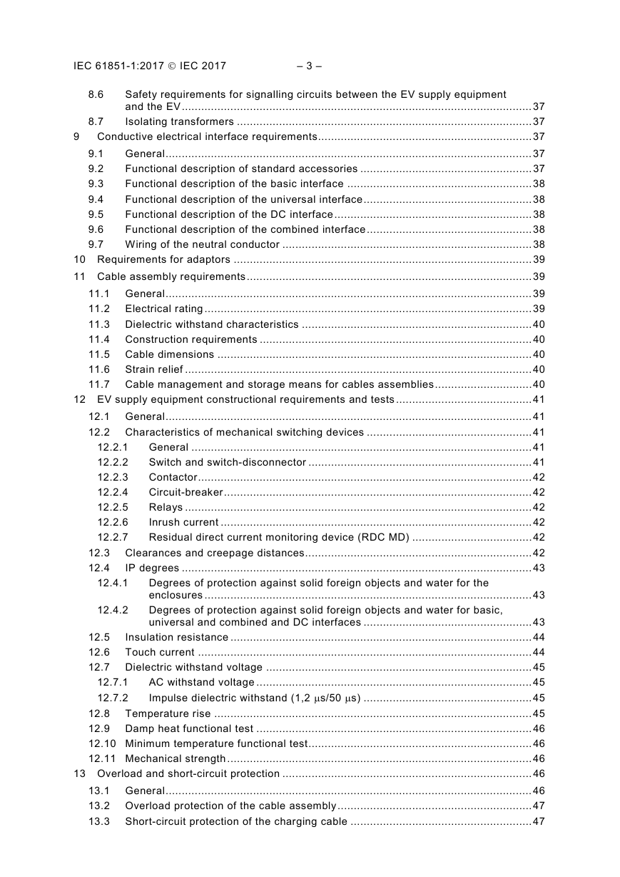
IEC 61851-1:2017  IEC 2017 – 3 – Degrees of protection against solid foreign objects and water for the Safety requirements for signalling circuits between the EV supply equipment 8.6 and the EV ............................................................................................................ 37 Isolating transformers ........................................................................................... 37 8.7 9 Conductive electrical interface requirements .................................................................. 37 9.1 General ................................................................................................................. 37 Functional description of standard accessories ..................................................... 37 9.2 9.3 Functional description of the basic interface ......................................................... 38 Functional description of the universal interface .................................................... 38 9.4 9.5 Functional description of the DC interface ............................................................. 38 Functional description of the combined interface ................................................... 38 9.6 9.7 Wiring of the neutral conductor ............................................................................. 38 10 Requirements for adaptors ............................................................................................ 39 11 Cable assembly requirements ........................................................................................ 39 11.1 General ................................................................................................................. 39 11.2 Electrical rating ..................................................................................................... 39 11.3 Dielectric withstand characteristics ....................................................................... 40 11.4 Construction requirements .................................................................................... 40 11.5 Cable dimensions ................................................................................................. 40 11.6 Strain relief ........................................................................................................... 40 11.7 Cable management and storage means for cables assemblies .............................. 40 12 EV supply equipment constructional requirements and tests .......................................... 41 12.1 General ................................................................................................................. 41 12.2 Characteristics of mechanical switching devices ................................................... 41 12.2.1 General ......................................................................................................... 41 12.2.2 Switch and switch-disconnector ..................................................................... 41 12.2.3 Contactor ....................................................................................................... 42 Circuit-breaker ............................................................................................... 42 12.2.4 12.2.5 Relays ........................................................................................................... 42 12.2.6 Inrush current ................................................................................................ 42 Residual direct current monitoring device (RDC MD) ..................................... 42 12.2.7 12.3 Clearances and creepage distances ...................................................................... 42 12.4 IP degrees ............................................................................................................ 43 12.4.1 enclosures ..................................................................................................... 43 12.4.2 universal and combined and DC interfaces .................................................... 43 12.5 Insulation resistance ............................................................................................. 44 12.6 Touch current ....................................................................................................... 44 12.7 Dielectric withstand voltage .................................................................................. 45 AC withstand voltage ..................................................................................... 45 12.7.1 Impulse dielectric withstand (1,2 µs/50 µs) .................................................... 45 12.7.2 12.8 Temperature rise .................................................................................................. 45 12.9 Damp heat functional test ..................................................................................... 46 12.10 Minimum temperature functional test ..................................................................... 46 12.11 Mechanical strength .............................................................................................. 46 13 Overload and short-circuit protection ............................................................................. 46 13.1 General ................................................................................................................. 46 13.2 Overload protection of the cable assembly ............................................................ 47 13.3 Short-circuit protection of the charging cable ........................................................ 47 Degrees of protection against solid foreign objects and water for basic,
– 4 – IEC 61851-1:2017  IEC 2017 Information on difficulties encountered with some legacy EVs for wake- Circuit diagram for vehicle couplers using an auxiliary switch associated with Annex A (normative) Control pilot function through a control pilot circuit using a PWM 14 Automatic reclosing of protective devices ...................................................................... 47 15 Emergency switching or disconnect (optional) ............................................................... 48 16 Marking and instructions ................................................................................................ 48 16.1 Installation manual of EV charging stations ........................................................... 48 16.2 User manual for EV supply equipment .................................................................. 49 16.3 Marking of EV supply equipment ........................................................................... 49 16.4 Marking of charging cable assemblies case B ....................................................... 49 16.5 Durability test for marking ..................................................................................... 50 signal and a control pilot wire................................................................................................ 51 A.1 General ................................................................................................................. 51 A.2 Control pilot circuit ................................................................................................ 51 General ......................................................................................................... 51 A.2.1 A.2.2 Typical control pilot circuit ............................................................................. 52 A.2.3 Simplified control pilot circuit ......................................................................... 53 A.2.4 Additional components and high frequency signals ........................................ 53 A.3 Requirements for parameters and system behaviour ............................................. 54 A.4 Test procedures .................................................................................................... 72 A.4.1 General ......................................................................................................... 72 Constructional requirements of the EV simulator ............................................ 72 A.4.2 A.4.3 Test procedure .............................................................................................. 72 A.4.4 Oscillator frequency and generator voltage test ............................................. 73 Duty cycle test ............................................................................................... 73 A.4.5 A.4.6 Pulse wave shape test ................................................................................... 74 A.4.7 Sequences test .............................................................................................. 74 A.4.8 Test of interruption of the protective conductor .............................................. 76 Test of short-circuit values of the voltage ....................................................... 76 A.4.9 A.4.10 Example of a test simulator of the vehicle (informative) ................................. 76 A.4.11 Optional hysteresis test ................................................................................. 79 Implementation hints ............................................................................................. 80 A.5 A.5.1 Retaining a valid authentication until reaching CP State B ............................. 80 A.5.2 Load control using transitions between state x1 and x2 ................................. 81 A.5.3 up after a long period of inactivity (informative) ............................................. 81 basic interface ...................................................................................................................... 82 B.1 the proximity detection contact .............................................................................. 82 B.2 Circuit for simultaneous proximity detection and current coding ............................ 83 couplers ................................................................................................................................ 86 C.1 General ................................................................................................................. 86 C.2 phase vehicle coupler ........................................................................................... 86 C.3 accessory without proximity switch ........................................................................ 90 C.4 Example of circuit diagram for Mode 4 connection using universal coupler ............ 91 the control pilot circuit ........................................................................................................... 93 Overview............................................................................................................... 93 D.1 Annex C (informative) Examples of circuit diagrams for a basic and universal vehicle Annex D (informative) Control pilot function that provides LIN communication using Annex B (normative) Proximity detection and cable current coding circuits for the Circuits diagrams for Mode 1, Mode 2 and Mode 3, using a basic single Circuits diagrams for Mode 3, using a basic single phase or three-phase --`,``,,`,``,,,`,`,,,```,,``,``-`-`,,`,,`,`,,`---
IEC 61851-1:2017  IEC 2017 – 5 – Test of short circuit between the control pilot conductor and the Control of latching and unlatching of IEC 62196-2 type 2 socket-outlets D.1.1 General ......................................................................................................... 93 D.1.2 LIN-CP features ............................................................................................. 93 Normative references .................................................................................... 93 D.1.3 Terms and abbreviations ............................................................................... 94 D.1.4 Scope and context ................................................................................................ 94 D.2 Overview of control pilot functions ........................................................................ 96 D.3 D.4 Control pilot circuit ................................................................................................ 97 D.4.1 General ......................................................................................................... 97 D.4.2 Control pilot circuit ......................................................................................... 97 Charging station control pilot circuit interface ................................................ 98 D.4.3 D.4.4 EV control pilot circuit interface ..................................................................... 99 D.4.5 LIN communication transceiver ...................................................................... 99 D.4.6 Optional cable assembly node ..................................................................... 100 D.5 Control pilot circuit interaction ............................................................................. 100 D.5.1 General ....................................................................................................... 100 D.5.2 Control pilot circuit states and transitions .................................................... 101 System requirements .......................................................................................... 102 D.6 D.6.1 General ....................................................................................................... 102 D.6.2 Control of LIN signals .................................................................................. 102 Control of the S2 switch and the vehicle load current ................................... 103 D.6.3 D.6.4 Control of the switching device in the charging station ................................. 103 D.6.5 and vehicle inlets ......................................................................................... 104 Charging sequences ........................................................................................... 105 D.7 D.7.1 General ....................................................................................................... 105 D.7.2 Start-up of normal AC charging sequence .................................................... 105 Normal EV-triggered stop of charging .......................................................... 107 D.7.3 D.7.4 Normal stop of charging triggered by charging station.................................. 109 LIN Communication ............................................................................................. 110 D.8 D.8.1 General ....................................................................................................... 110 Schedules.................................................................................................... 110 D.8.2 D.8.3 Frames ........................................................................................................ 117 D.8.4 Signals ........................................................................................................ 120 D.9 and PWM-CP ...................................................................................................... 128 D.9.1 General ....................................................................................................... 128 D.9.2 Interoperability between charging stations and EVs ..................................... 128 Control pilot circuit hardware ....................................................................... 129 D.9.3 D.9.4 Control pilot circuit functionality ................................................................... 129 D.9.5 Sequence to select LIN-CP or PWM-CP after plug-in ................................... 130 D.10 Procedures for test of charging stations .............................................................. 131 D.10.1 General ....................................................................................................... 131 D.10.2 Test of normal use ....................................................................................... 131 D.10.3 Test of disconnection under load ................................................................. 131 D.10.4 Overcurrent test ........................................................................................... 132 D.10.5 Test of interruption of LIN communication .................................................... 132 D.10.6 protective conductor .................................................................................... 132 D.10.7 Test of options ............................................................................................. 132 Requirements for charging stations and EVs that implement both LIN-CP --`,``,,`,``,,,`,`,,,```,,``,``-`-`,,`,,`,`,,`---
– 6 – IEC 61851-1:2017  IEC 2017 Annex E (informative) Charging station designed with a standard socket-outlet – Minimum gap for connection of Mode 2 cables with type E/F plug and Minimum gap for connection of Mode 2 cables with type BS1363 plug and Minimum gap for connection of Mode 2 cables with IEC 60309-2 straight Minimum gap for connection of Modes 1 and 2 cable assembly .......................................... 133 Overview............................................................................................................. 133 E.1 E.2 General ............................................................................................................... 133 E.3 socket-outlet systems ......................................................................................... 134 E.4 socket-outlet systems ......................................................................................... 134 E.5 plug and socket-outlet systems ........................................................................... 134 Bibliography ........................................................................................................................ 136 Figure 1 – Case A connection ............................................................................................... 18 Figure 2 – Case B connection ............................................................................................... 18 Figure 3 – Case C connection ............................................................................................... 19 Figure A.1 – Typical control pilot circuit (equivalent circuit) ................................................... 52 Figure A.2 – Simplified control pilot circuit (equivalent circuit) ............................................... 53 Figure A.3 – State diagram for typical control pilot (informative) ........................................... 60 Figure A.4 – State diagram for simplified control pilot (informative) ....................................... 61 Figure A.5 – Test sequence using a typical control pilot circuit.............................................. 75 Figure A.6 – Test sequence using the simplified control pilot circuit ...................................... 75 Figure A.7 – Optional test sequence with interruption by EV supply equipment ..................... 76 Figure A.8 – Example of a test circuit (EV simulator) ............................................................ 78 and no current coding ........................................................................................................... 82 current coding ....................................................................................................................... 84 Figure C.1 – Example of Mode 1 case B using the proximity circuit as in B.1 ........................ 87 Figure C.2 – Example of Mode 2 case B using proximity detection as in B.1 ......................... 88 Figure C.3 – Example of Mode 3 case B using proximity detection as in B.1 ......................... 89 Figure C.4 – Example of Mode 3 case C using proximity detection as in B.1 ......................... 90 proximity push button switch S3) ........................................................................................... 91 Figure C.6 – Example of Mode 4 case C using the universal vehicle coupler ......................... 92 functions, information flow and power flow ............................................................................ 95 circuit .................................................................................................................................... 98 Figure D.3 – Control pilot circuit state diagram for LIN-CP (key list in Table D.5) ................ 101 Figure D.4 – Example of timing diagram for start-up of normal AC charging sequence ........ 105 Figure D.5 – Timing diagram for normal EV-triggered stop of charging ................................ 107 charging station .................................................................................................................. 109 Figure D.7 – State diagram of the LIN node in the charging station ..................................... 111 equipped with accessories according to IEC 62196-2 .......................................................... 129 Figure D.2 – Electrical equivalent circuit for connection of LIN nodes to the control pilot Figure B.1 – Equivalent circuit diagram for proximity function using an auxiliary switch Figure C.5 – Example of Mode 3 case B using proximity detection as in B.2 (without Figure B.2 – Equivalent circuit diagram for simultaneous proximity detection and Figure D.1 – Example of an EV charging system with a typical configuration of Figure D.6 – Example of timing diagram for normal stop of charging triggered by Figure D.8 – Energy transfer between different charging stations and EVs that are --`,``,,`,``,,,`,`,,,```,,``,``-`-`,,`,,`,`,,`---
分享到:
收藏