where
L = luminance at a point on a surface in a particular viewing direction,
θ,ψ = spherical coordinates, declination, and azimuth, respectively,
dE(θ,ψ) = differential amount of illuminance at the point in the plane of the surface from a direction indicated by (θ,ψ),
fr(θ,ψ) = bidirectional reflectance distribution function (BRDF) of the surface material for a particular viewing direction.
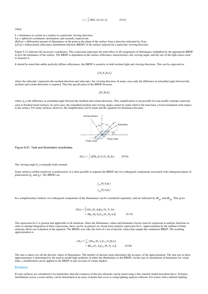
Figure 9-21 indicates the necessary coordinates. This expression represents the total effect of all components of illuminance multiplied by the appropriate BRDF
to give the luminance of the surface. The BRDF is dependent on the surface reflectance characteristics, the viewing angle, and the size of the light source used
to measure it.
It should be noted that unlike perfectly diffuse reflectances, the BRDF is sensitive to both incident light and viewing directions. This can be expressed as
where the subscript i represents the incident direction and subscript v the viewing direction. In many cases only the difference in azimuthal angle between the
incident and exitant directions is required. Then the specification of the BRDF becomes
where ψi is the difference in azimuthal angle between the incident and exitant directions. This simplification is not possible for non-axially-isotropic materials
such as brushed metal surfaces. In such cases, the azimuthal incident and viewing angles cannot be made relative but must have a fixed orientation with respect
to the surface. For many surfaces, however, the simplification can be made and the equation for luminance becomes
Figure 9-21. Task and illumination coordinates.
The viewing angle θv is normally held constant.
Some surfaces exhibit sensitivity to polarization. It is then possible to separate the BRDF into two orthogonal components associated with orthogonal planes of
polarization (p1 and p2). The BRDFs are
In a complementary fashion, two orthogonal components of the illuminance can be considered separately, and are indicated by dEp1 and dEp2. This gives
The expression for L is general and applicable to all situations. Since the illuminance values and luminance factors must be expressed as analytic functions in
order to attempt integration of these expressions, there can be, in general, no closed-form analytic expression for L. Approximation by the method of finite
elements allows an evaluation of the equation. The BRDFs now take the form of a set of discrete values that sample the continuous BRDF. The resulting
approximation is
The sum is taken over all the discrete values of illuminance. The number of discrete steps determines the accuracy of the approximation. The step size in these
approximations is determined by the need to model high gradients of either the illuminance or the BRDFs. In the case of calculations of luminance for visual
tasks, a modification can be applied to the BRDF to take account of a body shadow.
Exitance
If room surfaces are considered to be lambertian, then the exitances of discrete elements can be found using a flux transfer model described above. Exitance
distributions across a room surface can be determined at an array of points that cover it, using lighting analysis software. For rooms with a uniform lighting
�
system, average room surface exitances can be determined using the lumen method (see Example 5 in "Examples of Basic Lighting Calculations," in this
chapter).
CALCULATION OF DERIVED QUANTITIES
From the photometric quantities--illuminance, luminance, and exitance--it is possible to calculate other quantities that characterize how the human visual system
interprets or is affected by a visual scene. This section discusses a number of different quantities of this type and provides equations or references for use in their
computation.
Contrast
Contrast represents the difference in luminance between the task detail and its background relative to the luminance of the background or the luminances in the
visual scene. There are three different formulas for computing contrast, each of which providing a slightly different answer. See Chapter 3, Vision and
Perception, for definitions. See also Example 7 in "Examples of Basic Lighting Calculations," in this chapter.
Visual Performance and Visibility Metrics
Relative visual performance (RVP) and equivalent sphere illumination (ESI) are metrics for the evaluation of visual performance and visibility, respectively.
The calculation of these quantities requires the determination of the task and background luminances (to obtain the task contrast). The task size and adaptation
luminance are also needed. The equations needed to compute these quantities are provided in the references for Chapter 3, Vision and Perception, where they
are discussed in more detail.
Visual Comfort Probability (VCP)
Discomfort glare is the sensation of discomfort caused by luminances that are high relative to the average luminance in the field of view. The visual comfort
probability (VCP) is the probability that a normal observer does not experience discomfort when viewing a lighting system under defined conditions.
Equations for the calculation of the VCP are derived from correlating photometric and geometric characteristics of simple lighting patterns with discomfort
glare assessments of observers.61-68 Experiments in simulated rooms have been used to confirm the extension from the laboratory to actual lighting
installations.69,70 This system was tested and validated using lensed direct fluorescent systems only. VCP should not be applied to very small sources such as
incandescent and high-intensity discharge luminaires, to very large sources such as ceiling and indirect systems, or to nonuniform sources such as parabolic
reflectors.
To calculate the VCP71-81 several intermediate calculations must first be performed. The position index of a source, P, is an inverse measure of the relative
sensitivity to a glare source at different positions throughout the field of view. Selected values or families of curves were published in early references. P is
given by the formula79
where
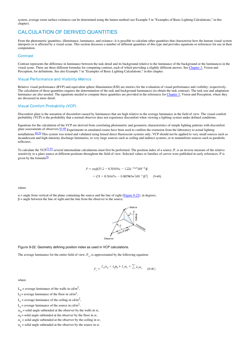
α = angle from vertical of the plane containing the source and the line of sight (Figure 9-22), in degrees,
β = angle between the line of sight and the line from the observer to the source.
Figure 9-22. Geometry defining position index as used in VCP calculations.
The average luminance for the entire field of view, Fv, is approximated by the following equation:
where
Lw = average luminance of the walls in cd/m2,
Lf = average luminance of the floor in cd/m2,
Lc = average luminance of the ceiling in cd/m2,
Ls = average luminance of the source in cd/m2,
ωw = solid angle subtended at the observer by the walls in sr,
ωf = solid angle subtended at the observer by the floor in sr,
ωc = solid angle subtended at the observer by the ceiling in sr,
ωs = solid angle subtended at the observer by the source in sr.
�
The 5 in the denominator arises from the assumption that the total field of view is 5 sr.79
A function Q has been developed for use in the calculation of the VCP. This function is given by
where ωs is the solid angle subtended at the observer by the source, in steradians. The values of P, Fv, and Q are used to determine the index of sensation, M:
The luminance in the above equation is expressed in cd/m2. The factor 0.50 in the numerator allows for the use of these units.
From the index of sensation of each source, a discomfort glare rating (DGR) can be calculated for the full field of view. The DGR is a metric of discomfort that
increases as discomfort increases; it is also used in calculating the VCP. It is given by
where
n = number of sources in the field of view,
Mi = index of sensation for the ith source.
The relation between DGR and VCP may be found from a graph such as Figure 9-23 or may be calculated by80
Figure 9-23. A chart for converting discomfort glare ratings (DGR) to VCP (the percentage of observers expected to judge a given lighting
condition to be either comfortable or at the borderline between comfort and discomfort).
These basic relations may be applied through a variety of techniques. Generally, the room cavity concept is used, in which the actual ceiling and floor
luminances and solid angles are replaced by their equivalent cavity values. The computation can be performed by summing throughout the enclosure.81
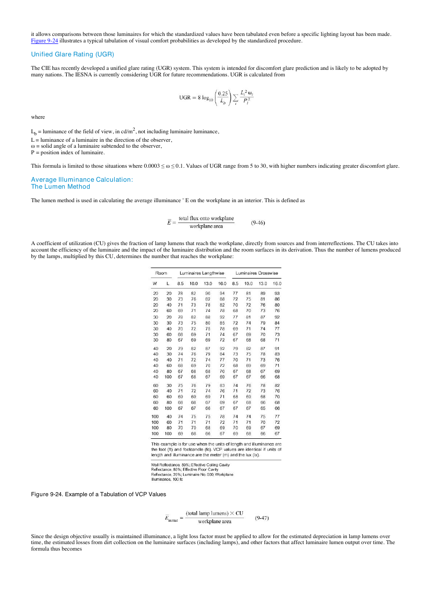
VCP values are frequently associated with luminaires under standardized conditions of use. In this method, the luminaires are fractionally apportioned over the
ceiling according to a standard scheme. VCP values are determined for:71,74,76
1. An initial average horizontal illuminance of 1000 lx (100 fc)
2. Room reflectances of ρCC = 0.80, ρW = 0.50, and ρFC = 0.20
3. Luminaire mounting heights above the floor of 2.6, 3, 4, and 4.9 m (8.5, 10, 13, and 16 ft)
4. A (given) range of room dimensions including square, long narrow, and short wide rooms
5. An observation point 1.2 m (4 ft) in front of the center of the rear wall and 1.2 m (4 ft) above the floor
6. A horizontal line of sight, directly forward
7. An upward limit to the field of view corresponding to an angle of 53° above and directly forward from the observer
There are two objectives in applying the standardized procedure. First, it simplifies calculations by permitting organization of various procedural steps. Second,
�
it allows comparisons between those luminaires for which the standardized values have been tabulated even before a specific lighting layout has been made.
Figure 9-24 illustrates a typical tabulation of visual comfort probabilities as developed by the standardized procedure.
Unified Glare Rating (UGR)
The CIE has recently developed a unified glare rating (UGR) system. This system is intended for discomfort glare prediction and is likely to be adopted by
many nations. The IESNA is currently considering UGR for future recommendations. UGR is calculated from
where
Lb = luminance of the field of view, in cd/m2, not including luminaire luminance,
L = luminance of a luminaire in the direction of the observer,
ω = solid angle of a luminaire subtended to the observer,
P = position index of luminaire.
This formula is limited to those situations where 0.0003 ≤ ω ≤ 0.1. Values of UGR range from 5 to 30, with higher numbers indicating greater discomfort glare.
Average Illuminance Calculation:
The Lumen Method
The lumen method is used in calculating the average illuminance ¯ E on the workplane in an interior. This is defined as
A coefficient of utilization (CU) gives the fraction of lamp lumens that reach the workplane, directly from sources and from interreflections. The CU takes into
account the efficiency of the luminaire and the impact of the luminaire distribution and the room surfaces in its derivation. Thus the number of lumens produced
by the lamps, multiplied by this CU, determines the number that reaches the workplane:
Figure 9-24. Example of a Tabulation of VCP Values
Since the design objective usually is maintained illuminance, a light loss factor must be applied to allow for the estimated depreciation in lamp lumens over
time, the estimated losses from dirt collection on the luminaire surfaces (including lamps), and other factors that affect luminaire lumen output over time. The
formula thus becomes
�
where
CU = coefficient of utilization,
LLF = light loss factor.
Although design calculations are based on the LLF using both nonrecoverable and recoverable factors, it is sometimes necessary to calculate illuminance in a
new lighting installation. In such cases, repeat the calculation using the nonrecoverable losses, since the recoverable losses do not occur at 100 hours, the time at
which lamps are nominally at rated lumens.
The lamp lumens in the formula are most conveniently taken as the total rated lamp lumens in the luminaires:
If the desired maintained illuminance is known, this equation can be solved for the total number of luminaires needed:
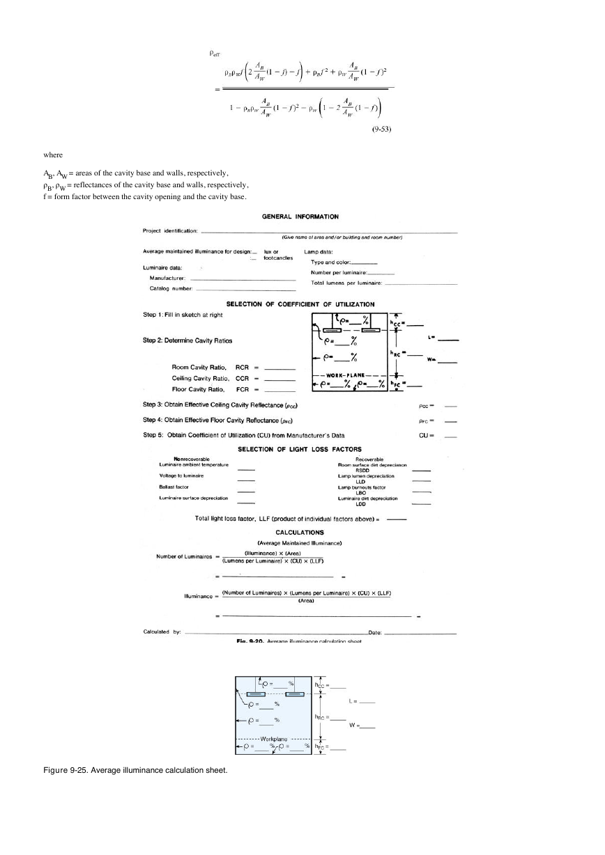
For a typical form for calculating illuminance, see Figure 9-25.
Limitations. The illuminance computed by the lumen method is an average value that is representative only if the luminaires are spaced to obtain reasonably
uniform illuminance. The calculation of the coefficients of utilization is based on empty interiors having surfaces that exhibit perfectly diffuse reflectance. The
average illuminance determined by the lumen method is defined to be the total lumens reaching the workplane divided by the area of the workplane. The
average value determined this way might vary considerably from that obtained by averaging discrete values of illuminance at several points.
Calculation Procedure. Figure 9-25 provides a procedure for calculating average maintained illuminance using the zonal-cavity method.44-46
Cavity Ratios. The radiative exchange between the top and the base of a rectangular space is a function of the proportions of its length, width, and height.
Cavity ratio values approximate this effect by combining these proportions into a single quantity.
In the zonal-cavity method, the effects of room proportions, luminaire suspension length, and workplane height upon the coefficient of utilization are
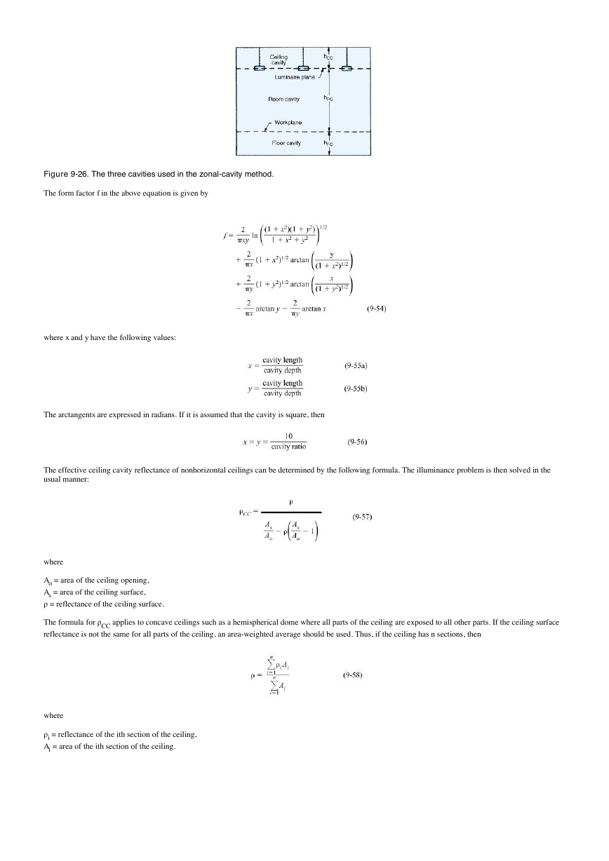
respectively represented by the room cavity ratio, ceiling cavity ratio, and floor cavity ratio. These ratios are determined by dividing the room into three cavities,
as shown by Figure 9-26, and substituting dimensions (in m or ft) into the following formula:
where
The illuminance in rooms of irregular shape can be determined by calculating the room cavity ratio using the following formula and solving the problem in the
usual manner:
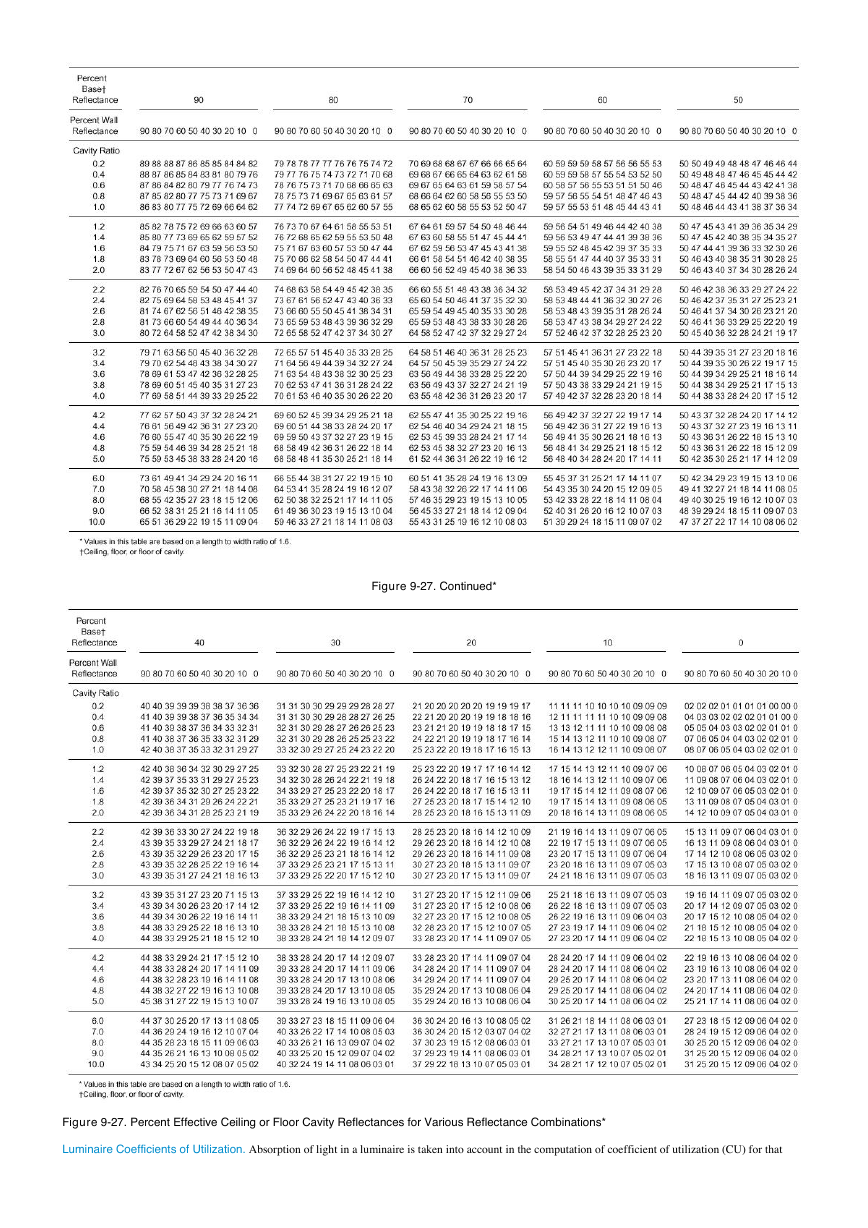
Effective Cavity Reflectances. Figure 9-27 provides a means of converting the combination of wall and ceiling or wall and floor reflectances into a single
effective ceiling cavity reflectance, ρCC, and a single effective floor cavity reflectance, ρFC. In lumen method calculations, the ceiling, wall, and floor
reflectances should be initial values. The RSDD factor compensates for the decrease of reflectance with time. Note that for surface-mounted and recessed
luminaires, the CCR equals 0 and the actual ceiling reflectance may be used for ρCC.
A rectangular cavity consists of four walls, each having a reflectance of ρW, and a base of reflectance ρB (ceiling or floor reflectance). The effective reflectance,
ρeff, of this cavity is the ratio of the flux reflected out to the flux entering the cavity through its opening. If the reflectances are assumed to be perfectly diffuse
and the flux is assumed to enter the cavity in a perfectly diffuse way, it is possible to calculate the effective cavity reflectance using flux transfer theory. The
result is
�
where
AB, AW = areas of the cavity base and walls, respectively,
ρB, ρW = reflectances of the cavity base and walls, respectively,
f = form factor between the cavity opening and the cavity base.
Figure 9-25. Average illuminance calculation sheet.
�
Figure 9-26. The three cavities used in the zonal-cavity method.
The form factor f in the above equation is given by
where x and y have the following values:
The arctangents are expressed in radians. If it is assumed that the cavity is square, then
The effective ceiling cavity reflectance of nonhorizontal ceilings can be determined by the following formula. The illuminance problem is then solved in the
usual manner:
where
Ao = area of the ceiling opening,
As = area of the ceiling surface,
ρ = reflectance of the ceiling surface.
The formula for ρCC applies to concave ceilings such as a hemispherical dome where all parts of the ceiling are exposed to all other parts. If the ceiling surface
reflectance is not the same for all parts of the ceiling, an area-weighted average should be used. Thus, if the ceiling has n sections, then
where
ρi = reflectance of the ith section of the ceiling,
Ai = area of the ith section of the ceiling.
�
Figure 9-27. Continued*
Figure 9-27. Percent Effective Ceiling or Floor Cavity Reflectances for Various Reflectance Combinations*
Luminaire Coefficients of Utilization. Absorption of light in a luminaire is taken into account in the computation of coefficient of utilization (CU) for that
�



 2023年江西萍乡中考道德与法治真题及答案.doc
 2012年重庆南川中考生物真题及答案.doc
 2013年江西师范大学地理学综合及文艺理论基础考研真题.doc
 2020年四川甘孜小升初语文真题及答案I卷.doc
 2020年注册岩土工程师专业基础考试真题及答案.doc
 2023-2024学年福建省厦门市九年级上学期数学月考试题及答案.doc
 2021-2022学年辽宁省沈阳市大东区九年级上学期语文期末试题及答案.doc
 2022-2023学年北京东城区初三第一学期物理期末试卷及答案.doc
 2018上半年江西教师资格初中地理学科知识与教学能力真题及答案.doc
 2012年河北国家公务员申论考试真题及答案-省级.doc
 2020-2021学年江苏省扬州市江都区邵樊片九年级上学期数学第一次质量检测试题及答案.doc
 2022下半年黑龙江教师资格证中学综合素质真题及答案.doc