M AN913
Interfacing the TC77 Thermal Sensor to a PICmicro®
Microcontroller
Author:
Steve Bible and Jim Lepkowski
Microchip Technology Inc.
INTRODUCTION
Silicon temperature sensors offer an easy-to-use alter-
native to traditional temperature sensors, such as ther-
mocouple, thermistors and RTDs. The TC77 SPI™
Thermal Silicon Sensor is especially suited for embed-
ded systems, due to its SPI interface. This serves to
provide a straight-forward and easy way to interface to
a microcontroller. This application note will discuss
system integration, firmware implementation and PCB
layout techniques for the TC77 in an embedded
system.
Microchip has developed a hardware platform called
the PICkit™ 1 FLASH Starter Kit, allowing the designer
to quickly begin their system development. Addition-
ally, Microchip has developed a TC77 PICtail™ Daugh-
ter Board that interfaces directly to the PICkit 1 FLASH
Starter Kit. These two boards are used to demonstrate
the techniques for integrating the TC77 into an embed-
ded systems environment. Both of these development
boards are available on the Microchip web site at
www.microchip.com.
is designed
is a
to demonstrate
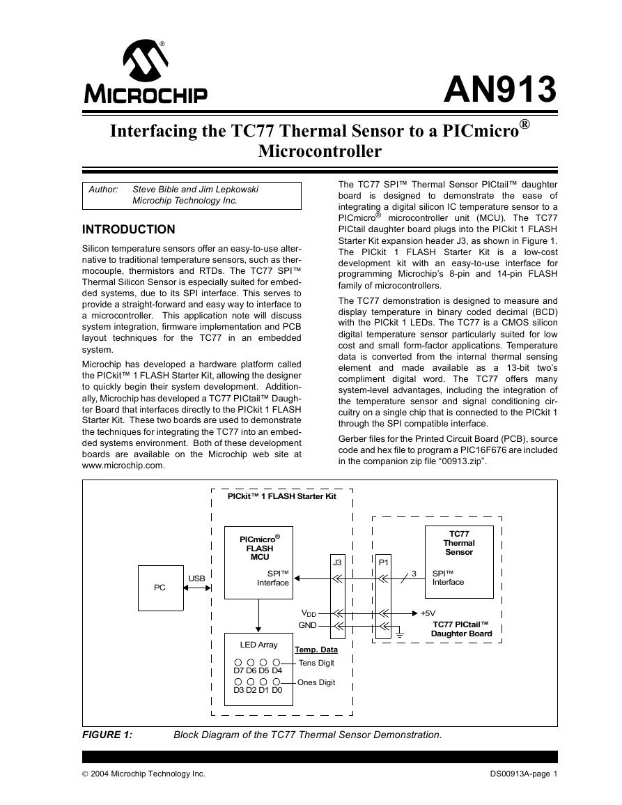
The TC77 SPI™ Thermal Sensor PICtail™ daughter
board
the ease of
integrating a digital silicon IC temperature sensor to a
PICmicro® microcontroller unit (MCU). The TC77
PICtail daughter board plugs into the PICkit 1 FLASH
Starter Kit expansion header J3, as shown in Figure 1.
The PICkit 1 FLASH Starter Kit
low-cost
development kit with an easy-to-use interface for
programming Microchip’s 8-pin and 14-pin FLASH
family of microcontrollers.
The TC77 demonstration is designed to measure and
display temperature in binary coded decimal (BCD)
with the PICkit 1 LEDs. The TC77 is a CMOS silicon
digital temperature sensor particularly suited for low
cost and small form-factor applications. Temperature
data is converted from the internal thermal sensing
element and made available as a 13-bit
two’s
compliment digital word. The TC77 offers many
system-level advantages, including the integration of
the temperature sensor and signal conditioning cir-
cuitry on a single chip that is connected to the PICkit 1
through the SPI compatible interface.
Gerber files for the Printed Circuit Board (PCB), source
code and hex file to program a PIC16F676 are included
in the companion zip file “00913.zip”.
PICkit™ 1 FLASH Starter Kit
PICmicro®
FLASH
MCU
SPI™
Interface
USB
PC
J3
P1
VDD
GND
Temp. Data
Tens Digit
Ones Digit
LED Array
D5D6D7
D4
D1D2D3
D0
TC77
Thermal
Sensor
3
SPI™
Interface
+5V
TC77 PICtail™
Daughter Board
FIGURE 1:
Block Diagram of the TC77 Thermal Sensor Demonstration.
2004 Microchip Technology Inc.
DS00913A-page 1
�
AN913
TC77 FUNCTIONAL DESCRIPTION
The TC77 consists of an internal diode temperature
sensor, a 13-bit Delta-Sigma, Analog-to-Digital
Converter (ADC), three digital registers and a SPI
compatible interface. The SPI compatible interface
provides for serial communication with microcontrol-
lers, such as a PICmicro microcontroller. Figure 2
provides a simplified block diagram of the TC77 sensor.
The temperature measurement data is stored in the
Temperature register, while the Configuration register
is used to select the operating mode of the sensor. The
Manufacturer’s Identification (ID) register is used to
identify the sensor as a Microchip component. Table 1
provides the bit definitions of the TC77 registers.
Operating Modes
The user-configured operating modes of the TC77
include a Continuous Temperature and a Shutdown
mode that are selected via the Configuration register. In
the Continuous Temperature mode, an ADC
conversion is performed approximately every 300 ms,
with the data being stored in the Temperature register.
If a Temperature register read operation is requested
while an ADC conversion is in progress, the previously
completed ADC conversion data will be outputted via
the sensor’s serial I/O port.
Shutdown mode can be used to minimize the power
consumption of the TC77 sensor when active tempera-
ture monitoring is not required. While Shutdown mode
disables the temperature conversion circuitry, the SPI
compatible interface remains active. The current con-
sumption of the sensor will be less than 1 µA when
Shutdown mode is activated.
VDD
VSS
Internal
Diode
Temperature
Sensor
13-Bit
Delta-Sigma
A/D Converter
Temperature
Register
TC77
Manufacturer
ID Register
Serial
Peripheral
Interface
(SPI™)
Configuration
Register
CS
SI/O
SCK
FIGURE 2:
Thermal Sensor.
Block Diagram of the TC77
TABLE 1:
TC77 DIGITAL REGISTERS
Register
Bit
15
Bit
14
Bit
13
Bit
12
Bit
11
Bit
10
Bit
9
Bit
8
Bit
7
Bit
6
Bit
5
Bit
4
Bit
3
Bit
2
Bit
1
Bit
0
Value at
Power-up/
Reset
Configuration
(Read/Write)
Temperature
(Read Only)
Manufacturer
ID (Read Only)
Legend:
C15 C14 C13 C12 C11 C10 C9
C8
C7
C6
C5
C4
C3 C2 C1 C0 Continuous
Temperature
Conversion
Mode **
(27)
T15 T14 T13 T12 T11 T10
(28)
(23)
***
0
(24)
(26)
(25)
1
1
0
0
1
T9
(23)
T8
(21)
T7
(20)
T6
(2-1)
T5
(2-2)
T4
(2-3)
T3
(2-4)
0
0
0
0
0
0
0
T2
*
0
T1
x
x
T0
x
Temp. = -2°C
x Bit 15 to Bit 8
= 54 hex
* Temperature Bit 2 = 0 during power-up; otherwise, bit 2 = 1
** C15:C0 = XXXX/XXXX 1111/1111 (Shutdown mode)
C15:C0 = XXXX/XXXX 0000/0000 (Continuous Conversion mode)
*** Temperature Register Bit 15 is the sign bit. If Bit 15 is equal to ‘1’, the temperature is negative
(T < 0°C). If Bit 15 is equal to ‘0’, the temperature is positive (T ≥ 0°C).
DS00913A-page 2
2004 Microchip Technology Inc.
�
AN913
Temperature Data Format
The TC77’s temperature data is represented by a 13-bit
two’s complement digital word as shown in Table 1 and
Table 2. The Least Significant bit (LSb) is equal to
0.0625°C. Note that the last two bits (bit T0 and T1) are
tri-stated and are represented as a logic ‘1’ in the table.
bit T2 is set to logic ‘1’ after the completion of the first
temperature conversion following a power-up or voltage
reset event.
Listed below is an example of the TC77’s Temperature
Register bit definition for a temperature of 85.125°C.
Example:
Temperature
= 85.125°C
Temperature Register
= 00101010 10010111b
= 26 + 24 + 22 + 20 + 2-3
= 64 + 16 + 4 + 1 + 0.125
= 85.125°C
TABLE 2:
TC77 TEMPERATURE OUTPUT
DATA
Temperature
Binary
Bit 15 Bit 0
+125°C
+25°C
+0.0625°C
0°C
-0.0625°C
-25°C
-55°C
0011 1110 1000 0111
0000 1100 1000 0111
0000 0000 0000 1111
0000 0000 0000 0111
1111 1111 1111 1111
1111 0011 1000 0111
1110 0100 1000 0111
the
SPI Compatible Interface
The TC77’s SPI compatible interface consists of the
Chip Select (CS), Serial Clock (SCK) and bidirectional
Serial
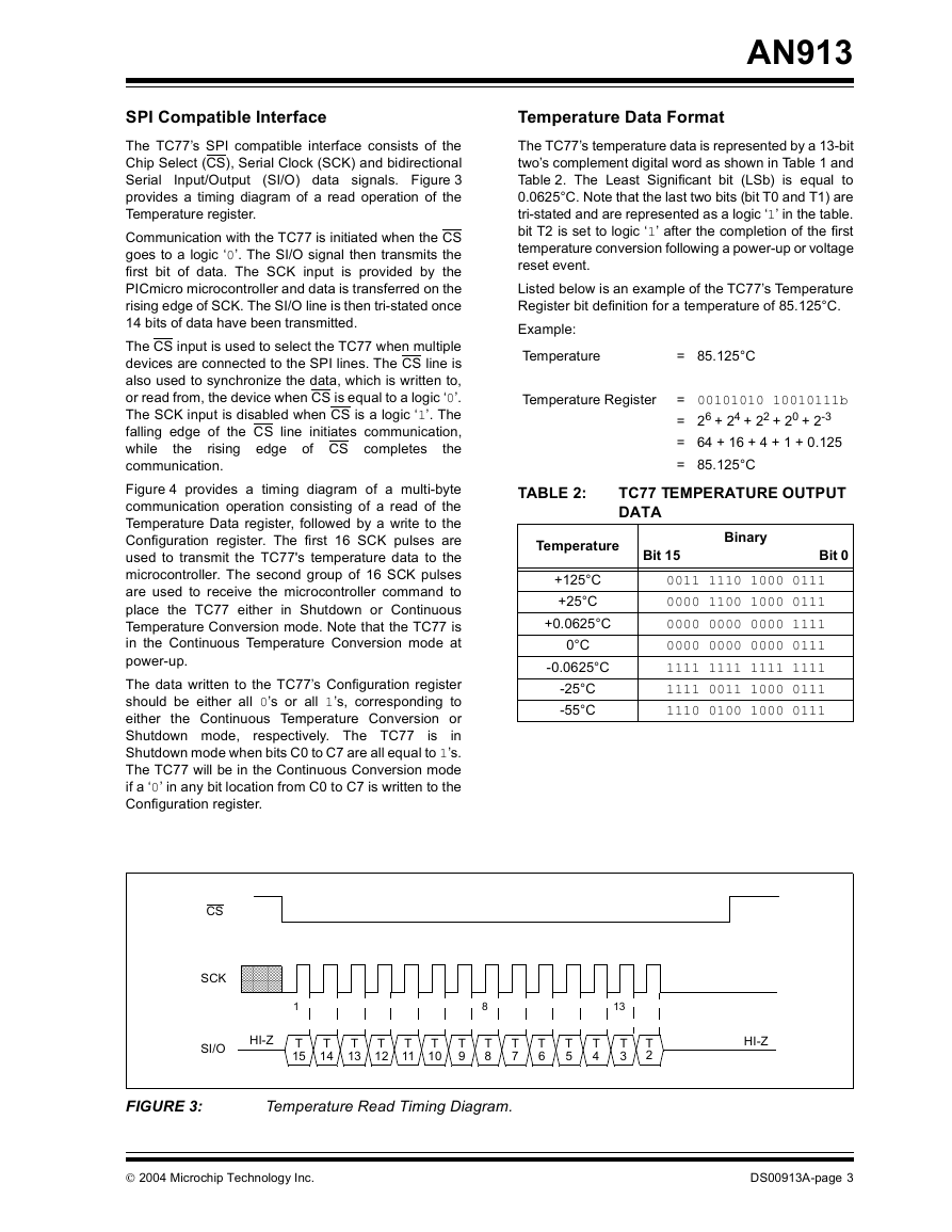
Input/Output (SI/O) data signals. Figure 3
provides a timing diagram of a read operation of the
Temperature register.
Communication with the TC77 is initiated when the CS
goes to a logic ‘0’. The SI/O signal then transmits the
first bit of data. The SCK input is provided by the
PICmicro microcontroller and data is transferred on the
rising edge of SCK. The SI/O line is then tri-stated once
14 bits of data have been transmitted.
The CS input is used to select the TC77 when multiple
devices are connected to the SPI lines. The CS line is
also used to synchronize the data, which is written to,
or read from, the device when CS is equal to a logic ‘0’.
The SCK input is disabled when CS is a logic ‘1’. The
falling edge of the CS line initiates communication,
while
the
communication.
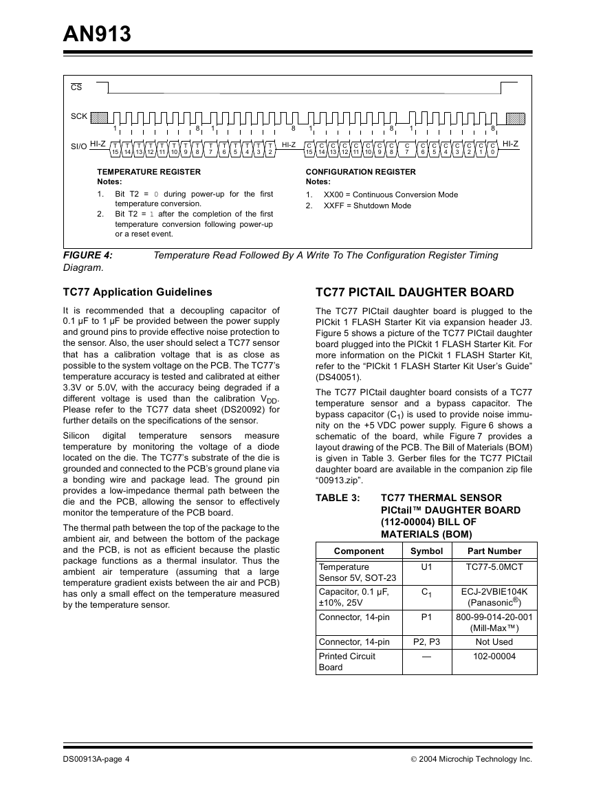
Figure 4 provides a timing diagram of a multi-byte
communication operation consisting of a read of the
Temperature Data register, followed by a write to the
Configuration register. The first 16 SCK pulses are
used to transmit the TC77's temperature data to the
microcontroller. The second group of 16 SCK pulses
are used to receive the microcontroller command to
place the TC77 either in Shutdown or Continuous
Temperature Conversion mode. Note that the TC77 is
in the Continuous Temperature Conversion mode at
power-up.
The data written to the TC77’s Configuration register
should be either all 0’s or all 1’s, corresponding to
either the Continuous Temperature Conversion or
Shutdown mode,
in
Shutdown mode when bits C0 to C7 are all equal to 1’s.
The TC77 will be in the Continuous Conversion mode
if a ‘0’ in any bit location from C0 to C7 is written to the
Configuration register.
rising edge of CS completes
respectively. The TC77
is
CS
SCK
���������������
���������������
HI-Z
SI/O
1
T
15
T
14
T
13
T
12
T
11
T
10
T
9
8
T
8
13
T
7
T
6
T
5
T
4
T
3
T
2
HI-Z
FIGURE 3:
Temperature Read Timing Diagram.
2004 Microchip Technology Inc.
DS00913A-page 3
�
AN913
CS
SCK
���������
���������
SI/O HI-Z
1
T
15
T
14
T
13
T
12
T
11
T
10
T
9
8
T
8
1
T
7
8
1
T
6
T
5
T
4
T
3
T
2
HI-Z
C
15
C
14
C
13
C
12
C
11
C
10
C
9
8
C
8
1
C
7
C
6
C
5
C
4
C
3
C
2
C
1
�����������
�����������
HI-Z
8
C
0
CONFIGURATION REGISTER
Notes:
1.
2.
XX00 = Continuous Conversion Mode
XXFF = Shutdown Mode
TEMPERATURE REGISTER
Notes:
1.
Bit T2 = 0 during power-up for the first
temperature conversion.
Bit T2 = 1 after the completion of the first
temperature conversion following power-up
or a reset event.
2.
FIGURE 4:
Diagram.
Temperature Read Followed By A Write To The Configuration Register Timing
digital
TC77 Application Guidelines
It is recommended that a decoupling capacitor of
0.1 µF to 1 µF be provided between the power supply
and ground pins to provide effective noise protection to
the sensor. Also, the user should select a TC77 sensor
that has a calibration voltage that is as close as
possible to the system voltage on the PCB. The TC77’s
temperature accuracy is tested and calibrated at either
3.3V or 5.0V, with the accuracy being degraded if a
different voltage is used than the calibration VDD.
Please refer to the TC77 data sheet (DS20092) for
further details on the specifications of the sensor.
Silicon
sensors measure
temperature by monitoring the voltage of a diode
located on the die. The TC77’s substrate of the die is
grounded and connected to the PCB’s ground plane via
a bonding wire and package lead. The ground pin
provides a low-impedance thermal path between the
die and the PCB, allowing the sensor to effectively
monitor the temperature of the PCB board.
The thermal path between the top of the package to the
ambient air, and between the bottom of the package
and the PCB, is not as efficient because the plastic
package functions as a thermal insulator. Thus the
ambient air temperature (assuming that a
large
temperature gradient exists between the air and PCB)
has only a small effect on the temperature measured
by the temperature sensor.
temperature
TC77 PICTAIL DAUGHTER BOARD
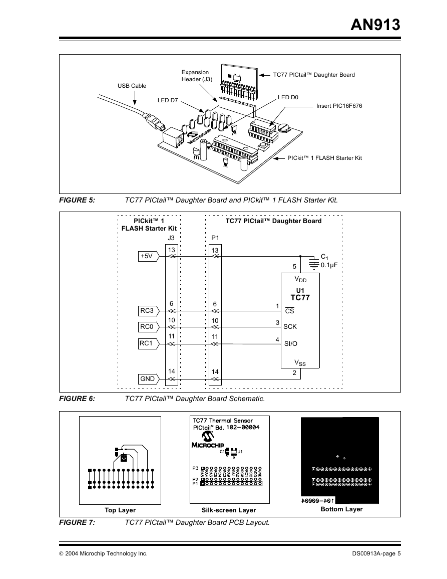
The TC77 PICtail daughter board is plugged to the
PICkit 1 FLASH Starter Kit via expansion header J3.
Figure 5 shows a picture of the TC77 PICtail daughter
board plugged into the PICkit 1 FLASH Starter Kit. For
more information on the PICkit 1 FLASH Starter Kit,
refer to the “PICkit 1 FLASH Starter Kit User’s Guide”
(DS40051).
The TC77 PICtail daughter board consists of a TC77
temperature sensor and a bypass capacitor. The
bypass capacitor (C1) is used to provide noise immu-
nity on the +5 VDC power supply. Figure 6 shows a
schematic of the board, while Figure 7 provides a
layout drawing of the PCB. The Bill of Materials (BOM)
is given in Table 3. Gerber files for the TC77 PICtail
daughter board are available in the companion zip file
“00913.zip”.
TABLE 3:
TC77 THERMAL SENSOR
PICtail™ DAUGHTER BOARD
(112-00004) BILL OF
MATERIALS (BOM)
Component
Symbol
Temperature
Sensor 5V, SOT-23
Capacitor, 0.1 µF,
±10%, 25V
Connector, 14-pin
U1
C1
P1
Connector, 14-pin
Printed Circuit
Board
P2, P3
—
Part Number
TC77-5.0MCT
ECJ-2VBIE104K
(Panasonic®)
800-99-014-20-001
(Mill-Max™)
Not Used
102-00004
DS00913A-page 4
2004 Microchip Technology Inc.
�
AN913
Expansion
Header (J3)
USB Cable
LED D7
TC77 PICtail™ Daughter Board
LED D0
Insert PIC16F676
PICkit™ 1 FLASH Starter Kit
FIGURE 5:
TC77 PICtail™ Daughter Board and PICkit™ 1 FLASH Starter Kit.
PICkit™ 1
FLASH Starter Kit
J3
13
+5V
6
10
11
14
RC3
RC0
RC1
GND
TC77 PICtail™ Daughter Board
P1
13
6
10
11
14
C1
0.1µF
5
VDD
U1
TC77
CS
SCK
SI/O
1
3
4
VSS
2
FIGURE 6:
TC77 PICtail™ Daughter Board Schematic.
M
M
Top Layer
Silk-screen Layer
Bottom Layer
FIGURE 7:
TC77 PICtail™ Daughter Board PCB Layout.
2004 Microchip Technology Inc.
DS00913A-page 5
�
TABLE 4:
LED LAMP ANNUNCIATION
LED Annuciation
Binary
BCD
0000
0001
0010
0011
0100
0101
0110
0111
1000
1001
0
1
2
3
4
5
6
7
8
9
D7
D3
OFF
OFF
OFF
OFF
OFF
OFF
OFF
OFF
ON
ON
D6
D2
OFF
OFF
OFF
OFF
ON
ON
ON
ON
OFF
OFF
D5
D1
OFF
OFF
ON
ON
OFF
OFF
ON
ON
OFF
OFF
D4
D0
OFF
ON
OFF
ON
OFF
ON
OFF
ON
OFF
ON
AN913
TC77 Interface Software
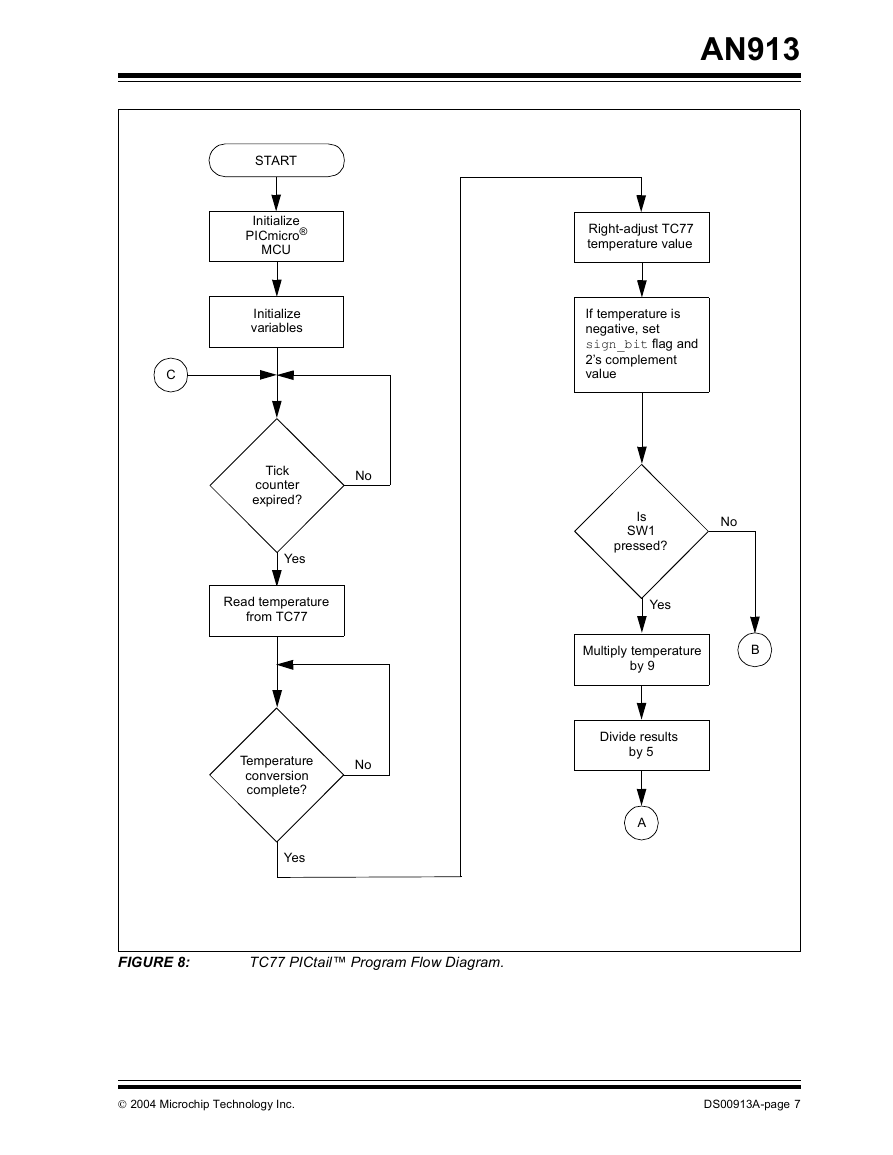
A flow diagram for the PICkit 1 software is given in
Figure 8. The TC77 thermal sensor is read by the
PICmicro microcontroller. Bit T2 of the Temperature
register is tested to ensure that the TC77 sensor is
powered up and ready. The value read from the TC77
is right-adjusted in the register as a 12-bit temperature
value in degrees Celsius. The temperature value is
tested for a negative temperature reading by checking
the status of bit T15. If the value is negative (T < 0°C),
the state is saved in a flag bit and the value is 2’s
complemented.
The TC77’s Temperature
register provides a
temperature measurement in Celsius. A provision in
the software is provided to display the temperature in
either Fahrenheit or Celsius by testing the status of the
PICkit 1 push button switch (SW1). If SW1 is not
depressed, the temperature value is converted to
Fahrenheit. Otherwise, if the push button is depressed,
the conversion routine is skipped and the data is
displayed in Celsius. Finally, the temperature value is
loaded into the LEDREG variable to be displayed on
the LEDs by the DISPLAY subroutine.
The temperature measurement is displayed using the
red LEDs designated as D0 through D7 located on the
PICkit board. The ten's digit of the temperature data is
represented by bits D7 to D4, with D7 being defined as
the Most Significant bit (MSb). The one's digit is defined
by bits D3 to D0, with D3 serving as the MSb. Table 4
provides a list of the LED lamp annunciation that corre-
sponds to the BCD coding representation of the tem-
perature measurement. For example, a temperature
reading of 70°F will be displayed by illuminating LEDs
D4, D5 and D6. If the SW1 push button is activated, a
measurement of 21°C will be shown by illuminating
LEDs D0 and D5. A fractional temperature is rounded
up if the tenths digit is determined to be either 0.5°F or
0.5°C.
Fully documented source code and a hex file ready to
program
into a PIC16F676
the
companion zip file “00913.zip”.
is available
in
DS00913A-page 6
2004 Microchip Technology Inc.
�
AN913
Right-adjust TC77
temperature value
If temperature is
negative, set
sign_bit flag and
2’s complement
value
Is
SW1
pressed?
No
Yes
Multiply temperature
by 9
B
Divide results
by 5
A
START
Initialize
PICmicro®
MCU
Initialize
variables
C
No
Tick
counter
expired?
Yes
Read temperature
from TC77
Temperature
conversion
complete?
No
Yes
FIGURE 8:
TC77 PICtail™ Program Flow Diagram.
2004 Microchip Technology Inc.
DS00913A-page 7
�
AN913
B
A
Add 32
Round result
to an integer
Convert value
to BCD
Place value in
LEDREG
C
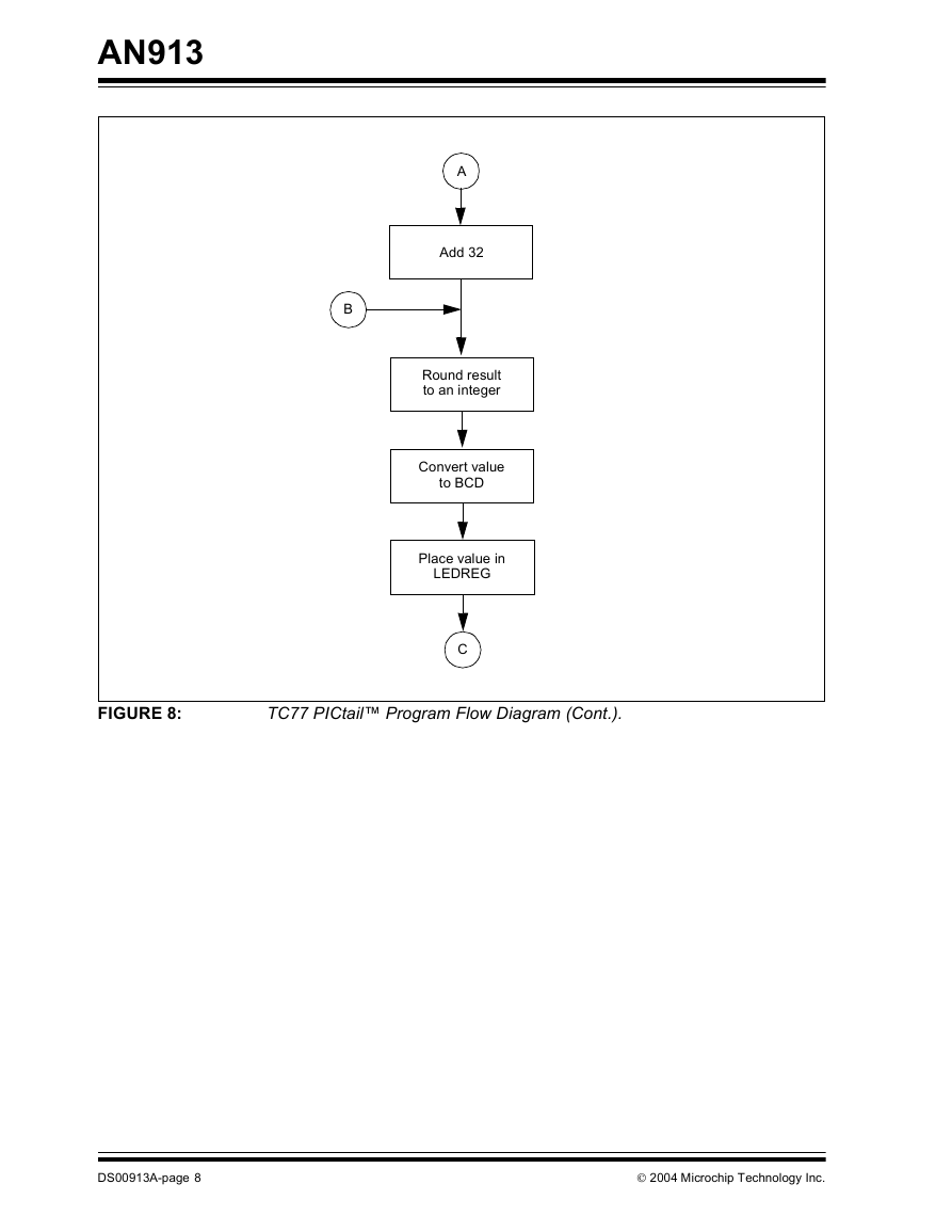
FIGURE 8:
TC77 PICtail™ Program Flow Diagram (Cont.).
DS00913A-page 8
2004 Microchip Technology Inc.
�




 2023年江西萍乡中考道德与法治真题及答案.doc
 2012年重庆南川中考生物真题及答案.doc
 2013年江西师范大学地理学综合及文艺理论基础考研真题.doc
 2020年四川甘孜小升初语文真题及答案I卷.doc
 2020年注册岩土工程师专业基础考试真题及答案.doc
 2023-2024学年福建省厦门市九年级上学期数学月考试题及答案.doc
 2021-2022学年辽宁省沈阳市大东区九年级上学期语文期末试题及答案.doc
 2022-2023学年北京东城区初三第一学期物理期末试卷及答案.doc
 2018上半年江西教师资格初中地理学科知识与教学能力真题及答案.doc
 2012年河北国家公务员申论考试真题及答案-省级.doc
 2020-2021学年江苏省扬州市江都区邵樊片九年级上学期数学第一次质量检测试题及答案.doc
 2022下半年黑龙江教师资格证中学综合素质真题及答案.doc