logo资料库

E524.08(09) datasheet.pdf

第1页 / 共76页
第2页 / 共76页
第3页 / 共76页
第4页 / 共76页
第5页 / 共76页
第6页 / 共76页
第7页 / 共76页
第8页 / 共76页
资料共76页,剩余部分请下载后查看
Features
Applications
Ordering Information
General Description
Typical Operating Circuit
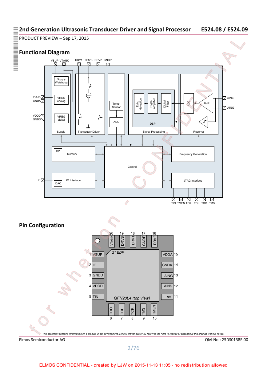
Functional Diagram
Pin Configuration
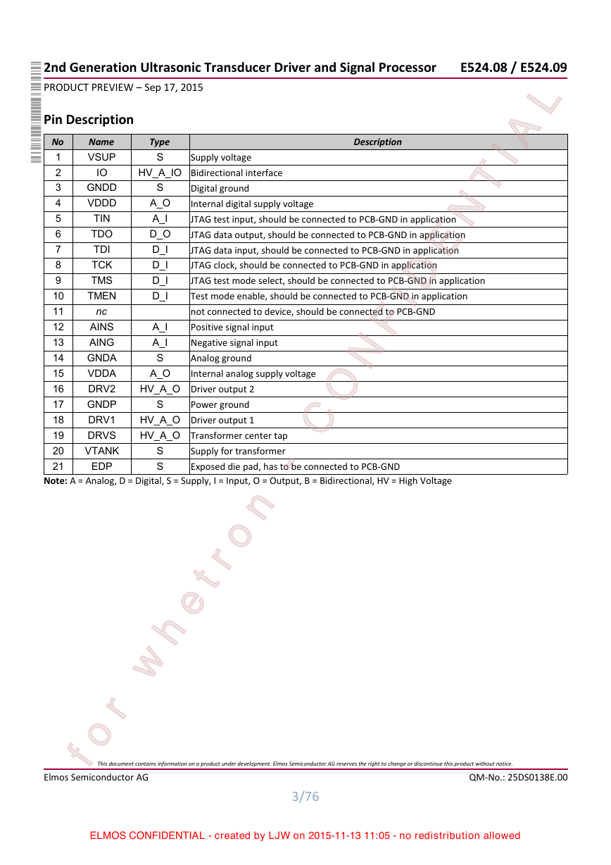
Pin Description
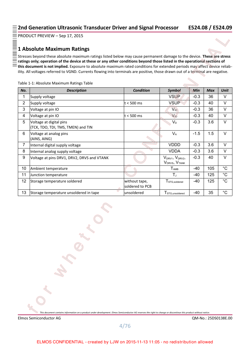
1 Absolute Maximum Ratings
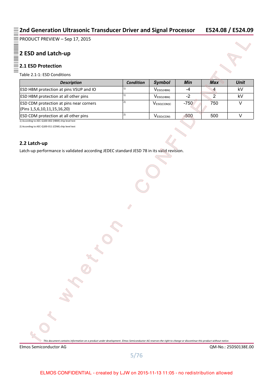
2 ESD and Latch-up
2.1 ESD Protection
2.2 Latch-up
3 Recommended Operating Conditions
4 Electrical Characteristics
4.1 Power Supply
4.2 Frequency generation
4.3 Transducer driver
4.4 Receiver
4.5 Signal Processing
4.6 Temperature sensor
4.7 IO Interface
5 Functional Description
5.1 Overview
5.1.1 Ultrasonic distance measurement
5.1.2 Measurement cycle
5.1.3 Measurement modes
5.1.4 Interface
5.2 Power Supply
5.2.1 Analog supply
5.2.2 Digital supply
5.2.3 VSUP Watchdog
5.2.4 Power up sequence
5.2.5 Standby mode
5.3 Frequency generation
5.3.1 Oscillator frequency configuration
5.4 Transducer driver
5.4.1 Configuration
5.4.1.1 Burst frequency configuration
5.4.1.2 Driver current configuration
5.4.1.3 Burst length configuration
5.5 Receiver
5.5.1 Analog Amplifier
5.5.2 Analog to Digital Conversion (ADC)
5.6 Signal Processing
5.6.1 Digital Filter
5.6.1.1 Filter characteristics
5.6.2 Digital Amplifier and Sensitivity Time Control (STC)
5.6.3 Echo detection
5.6.3.1 Static threshold curve
5.6.3.2 Values of static threshold generation
5.6.3.3 Automatic threshold generation (ATG)
5.6.3.4 Noise measurement during SEND and RECEIVE command
5.6.3.5 Echo detection type
5.6.3.6 Echo peak detection during overdrive
5.6.4 Signal enhancement
5.6.4.1 Fast Time Constant (FTC)
5.6.4.2 Near Field Threshold Generation (NFTG)
5.6.4.3 Ringing time (RT)
5.6.5 Measurement time
5.7 Temperature sensor
5.8 Memory and device configuration
5.8.1 "Measurement Setup" and "Threshold Setup"
5.8.2 "Calibration Setup"
5.9 IO Interface
5.9.1 Exchange of commands
5.9.2 'SEND' and 'RECEIVE' Commands
5.9.2.1 'SEND_A' command
5.9.2.2 'SEND_B' and 'SEND_C' command
5.9.2.3 'RECEIVE_A' command
5.9.2.4 'RECEIVE_B' and 'RECEIVE_C' command
5.9.2.5 Status information after 'SEND' and 'RECEIVE' commands
5.9.3 'THRES_SETUP' command
5.9.4 'MEAS_SETUP' command
5.9.5 'READ_STATUS' command
5.9.6 'CAL_PULSES' command
5.9.7 'READ_TEMP'
5.9.8 'ENVELOPE_SEND_A' and 'ENVELOPE_REC_A' commands
5.9.9 EEPROM Programming
5.9.9.1 'CALIB_WRITE' Command
5.9.9.2 'CALIB_READ' command
5.9.9.3 'EE_COPY' Command
5.9.9.4 'EE_READ' Command
5.9.10 'READ_ID' command
5.9.11 'STANDBY' and 'WAKE_UP' command
6 Package Reference
7 Typical Applications
7.1 Typical Application Circuit E524.08
7.2 External Components E524.08
7.3 Typical Application Circuit E524.09
7.4 External Components E524.09
8 Marking
8.1 Top Side
8.2 Bottom Side
9 Reliability
9.1 EEPROM Data Retention
10 Abbreviations
11 General
11.1 WARNING - Life Support Applications Policy
11.2 General Disclaimer
11.3 Application Disclaimer
12 Contact Info
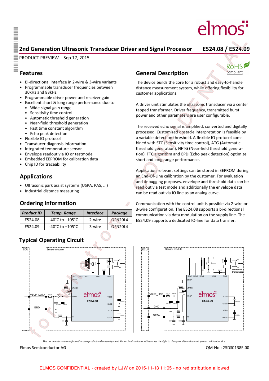
2nd Generation Ultrasonic Transducer Driver and Signal Processor PRODUCT PREVIEW – Sep 17, 2015 L E524.08 / E524.09 General Description The device builds the core for a robust and easy-to-handle distance measurement system, while offering flexibility for customer applications. TIA N E FID N The received echo signal is amplified, converted and digitally processed. Customized obstacle interpretation is feasible by a variable detection threshold. A flexible IO protocol com- bined with STC (Sensitivity time control), ATG (Automatic threshold generation), NFTG (Near-field threshold genera- tion), FTC algorithm and EPD (Echo peak detection) optimize short and long range performance. A driver unit stimulates the ultrasonic transducer via a center tapped transformer. Driver frequency, transmitted burst power and other parameters are user configurable. Application relevant settings can be stored in EEPROM during an End-Of-Line calibration by the customer. For evaluation and debugging purposes, envelope and threshold data can be read out via test mode and additionally the envelope data can be read out via IO line as an analog curve. O Communication with the control unit is possible via 2-wire or 3-wire configuration. The E524.08 supports a bi-directional communication via data modulation on the supply line. The E524.09 supports a dedicated IO-line for data transfer. n - C Package QFN20L4 QFN20L4 Features • Bi-directional interface in 2-wire & 3-wire variants • Programmable transducer frequencies between 30kHz and 83kHz • Programmable driver power and receiver gain • Excellent short & long range performance due to: • Wide signal gain range • Sensitivity time control • Automatic threshold generation • Near-field threshold generation • Fast time constant algorithm • Echo peak detection • Flexible IO protocol • Transducer diagnosis information • Integrated temperature sensor • Envelope readout via IO or testmode • Embedded EEPROM for calibration data • Chip ID for traceability Applications • Ultrasonic park assist systems (USPA, PAS, ...) • Industrial distance measuring Ordering Information Temp. Range Product ID E524.08 -40°C to +105°C -40°C to +105°C E524.09 Interface 2-wire 3-wire Typical Operating Circuit ECU TR1 CAIN1 I 2 N A C I N A R D T R D T C Sensor module o etr h r w fo VSUP_DATA E524.08 DRV1 GNDP DRVS DRV2 GND CSUP1 CSUP2 RSUP DSUP VTANK VSUP RTANK CSUP3 AING AINS RIO_S CIO IO VDDD GNDD VDDA GNDA ECU Sensor module D T R D T C TR1 CAIN1 I 2 N A C I N A R Ultrasonic transducer DRV1 DRVS DRV2 AING AINS GNDP VTANK VSUP RTANK CSUP3 VSUP_LINE RSUP DSUP GND DATA CSUP1 CSUP2 RPU RIO_S IO CIO1 CIO2 E524.09 VDDD GNDD VDDA GNDA CVDDD CVDDA CVDDD CVDDA This document contains information on a product under development. Elmos Semiconductor AG reserves the right to change or discontinue this product without notice. Elmos Semiconductor AG QM-No.: 25DS0138E.00 ELMOS CONFIDENTIAL - created by LJW on 2015-11-13 11:05 - no redistribution allowed
L 2nd Generation Ultrasonic Transducer Driver and Signal Processor PRODUCT PREVIEW – Sep 17, 2015 E524.08 / E524.09 Functional Diagram VSUP VTANK DRV1 DRVS DRV2 GNDP Supply Watchdog VREG analog VREG digital VDDA GNDA VDDD GNDD Temp. Sensor ADC o h c E n o i t c e t e d Supply Transducer Driver CP Memory Control l a r e TIA N E FID N Frequency Generation Receiver AMP C D A g D t l i F t i i AINS AING l a t i i g D r e i f i l p m A DSP Signal Processing O n - C 20 K N A T V 19 S V R D 18 1 V R D 17 P D N G 16 2 V R D 21 EDP QFN20L4 (top view) I D T 7 K C T 8 S M T 9 N E M T 10 O D T 6 JTAG Interface TIN TMEN TCK TDI TDO TMS VDDA 15 GNDA 14 AING 13 AINS 12 nc 11 IO IO Interface IDAC Pin Configuration 2 1 IO VSUP o etr h r w fo GNDD VDDD TIN 3 4 5 Elmos Semiconductor AG This document contains information on a product under development. Elmos Semiconductor AG reserves the right to change or discontinue this product without notice. 2/76 QM-No.: 25DS0138E.00 ELMOS CONFIDENTIAL - created by LJW on 2015-11-13 11:05 - no redistribution allowed
2nd Generation Ultrasonic Transducer Driver and Signal Processor PRODUCT PREVIEW – Sep 17, 2015 E524.08 / E524.09 L Type S Supply voltage HV_A_IO Bidirectional interface Description TIA N E FID N Digital ground Internal digital supply voltage JTAG test input, should be connected to PCB-GND in application JTAG data output, should be connected to PCB-GND in application JTAG data input, should be connected to PCB-GND in application JTAG clock, should be connected to PCB-GND in application JTAG test mode select, should be connected to PCB-GND in application Test mode enable, should be connected to PCB-GND in application not connected to device, should be connected to PCB-GND Positive signal input Negative signal input Analog ground Internal analog supply voltage S A_O A_I D_O D_I D_I D_I D_I A_I A_I S A_O O S HV_A_O Driver output 2 Power ground HV_A_O Driver output 1 HV_A_O Transformer center tap Supply for transformer Exposed die pad, has to be connected to PCB-GND S S n - C Note: A = Analog, D = Digital, S = Supply, I = Input, O = Output, B = Bidirectional, HV = High Voltage IO Name VSUP GNDD VDDD TIN TDO TDI TCK TMS TMEN Pin Description No 1 2 3 4 5 6 7 8 9 10 11 12 13 14 15 16 17 18 19 20 21 nc AINS AING GNDA VDDA DRV2 GNDP DRV1 DRVS VTANK EDP o etr h r w fo Elmos Semiconductor AG This document contains information on a product under development. Elmos Semiconductor AG reserves the right to change or discontinue this product without notice. 3/76 QM-No.: 25DS0138E.00 ELMOS CONFIDENTIAL - created by LJW on 2015-11-13 11:05 - no redistribution allowed
2nd Generation Ultrasonic Transducer Driver and Signal Processor PRODUCT PREVIEW – Sep 17, 2015 E524.08 / E524.09 1 Absolute Maximum Ratings Stresses beyond these absolute maximum ratings listed below may cause permanent damage to the device. These are stress ratings only; operation of the device at these or any other conditions beyond those listed in the operational sections of this document is not implied. Exposure to absolute maximum rated conditions for extended periods may affect device reliab- ility. All voltages referred to VGND. Currents flowing into terminals are positive, those drawn out of a terminal are negative. L TIA N E FID N Min Max -0.3 36 40 -0.3 36 -0.3 -0.3 40 3.6 -0.3 Symbol VSUP VSUP VDDD VDDA VIO VIO VD VA -1.5 -0.3 -0.3 -0.3 1.5 3.6 3.6 40 VDRV1, VDRV2, VDRVS, VTANK TAMB TJ TSTG,soldered TSTG,unsoldered -40 -40 -40 -40 105 125 125 35 Unit V V V V V V V V V °C °C °C °C This document contains information on a product under development. Elmos Semiconductor AG reserves the right to change or discontinue this product without notice. 4/76 QM-No.: 25DS0138E.00 ELMOS CONFIDENTIAL - created by LJW on 2015-11-13 11:05 - no redistribution allowed Description Condition t < 500 ms t < 500 ms O n - C without tape, soldered to PCB unsoldered Table 1-1: Absolute Maximum Ratings Table No. 1 2 3 4 5 6 7 8 9 Supply voltage Supply voltage Voltage at pin IO Voltage at pin IO Voltage at digital pins (TCK, TDO, TDI, TMS, TMEN) and TIN Voltage at analog pins (AINS, AING) Internal digital supply voltage Internal analog supply voltage Voltage at pins DRV1, DRV2, DRVS and VTANK 10 Ambient temperature 11 Junction temperature 12 Storage temperature soldered 13 Storage temperature unsoldered in tape o etr h r w fo Elmos Semiconductor AG
2nd Generation Ultrasonic Transducer Driver and Signal Processor PRODUCT PREVIEW – Sep 17, 2015 E524.08 / E524.09 2 ESD and Latch-up 2.1 ESD Protection Table 2.1-1: ESD Conditions Description Condition ESD HBM protection at pins VSUP and IO ESD HBM protection at all other pins ESD CDM protection at pins near corners (Pins 1,5,6,10,11,15,16,20) ESD CDM protection at all other pins 1) According to AEC-Q100-002 (HBM) chip level test 2) According to AEC-Q100-011 (CDM) chip level test 1) 1) 2) 2) 2.2 Latch-up Latch-up performance is validated according JEDEC standard JESD 78 in its valid revision. L Symbol VESD(HBM) VESD(HBM) VESD(CDM)C VESD(CDM) Min -4 -2 -750 TIA N E FID N -500 Max 4 2 750 500 Unit kV kV V V O n - C o etr h r w fo Elmos Semiconductor AG This document contains information on a product under development. Elmos Semiconductor AG reserves the right to change or discontinue this product without notice. 5/76 QM-No.: 25DS0138E.00 ELMOS CONFIDENTIAL - created by LJW on 2015-11-13 11:05 - no redistribution allowed
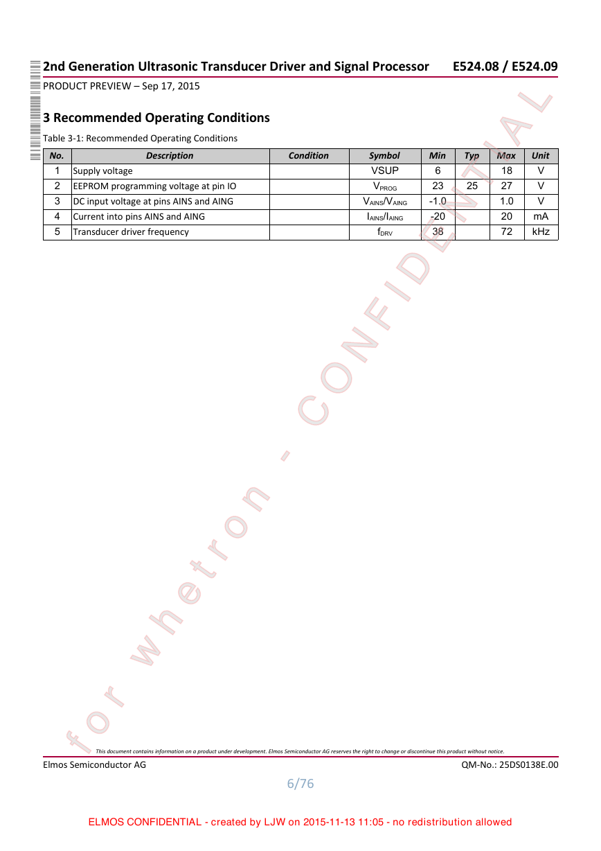
2nd Generation Ultrasonic Transducer Driver and Signal Processor PRODUCT PREVIEW – Sep 17, 2015 E524.08 / E524.09 3 Recommended Operating Conditions Table 3-1: Recommended Operating Conditions No. 1 2 3 4 5 Description Condition Supply voltage EEPROM programming voltage at pin IO DC input voltage at pins AINS and AING Current into pins AINS and AING Transducer driver frequency L Unit V V V mA kHz Symbol VSUP VPROG VAINS/VAING IAINS/IAING fDRV 25 Min 6 23 -1.0 -20 38 Typ Max 18 27 1.0 20 72 TIA N E FID N This document contains information on a product under development. Elmos Semiconductor AG reserves the right to change or discontinue this product without notice. 6/76 QM-No.: 25DS0138E.00 ELMOS CONFIDENTIAL - created by LJW on 2015-11-13 11:05 - no redistribution allowed O n - C o etr h r w fo Elmos Semiconductor AG
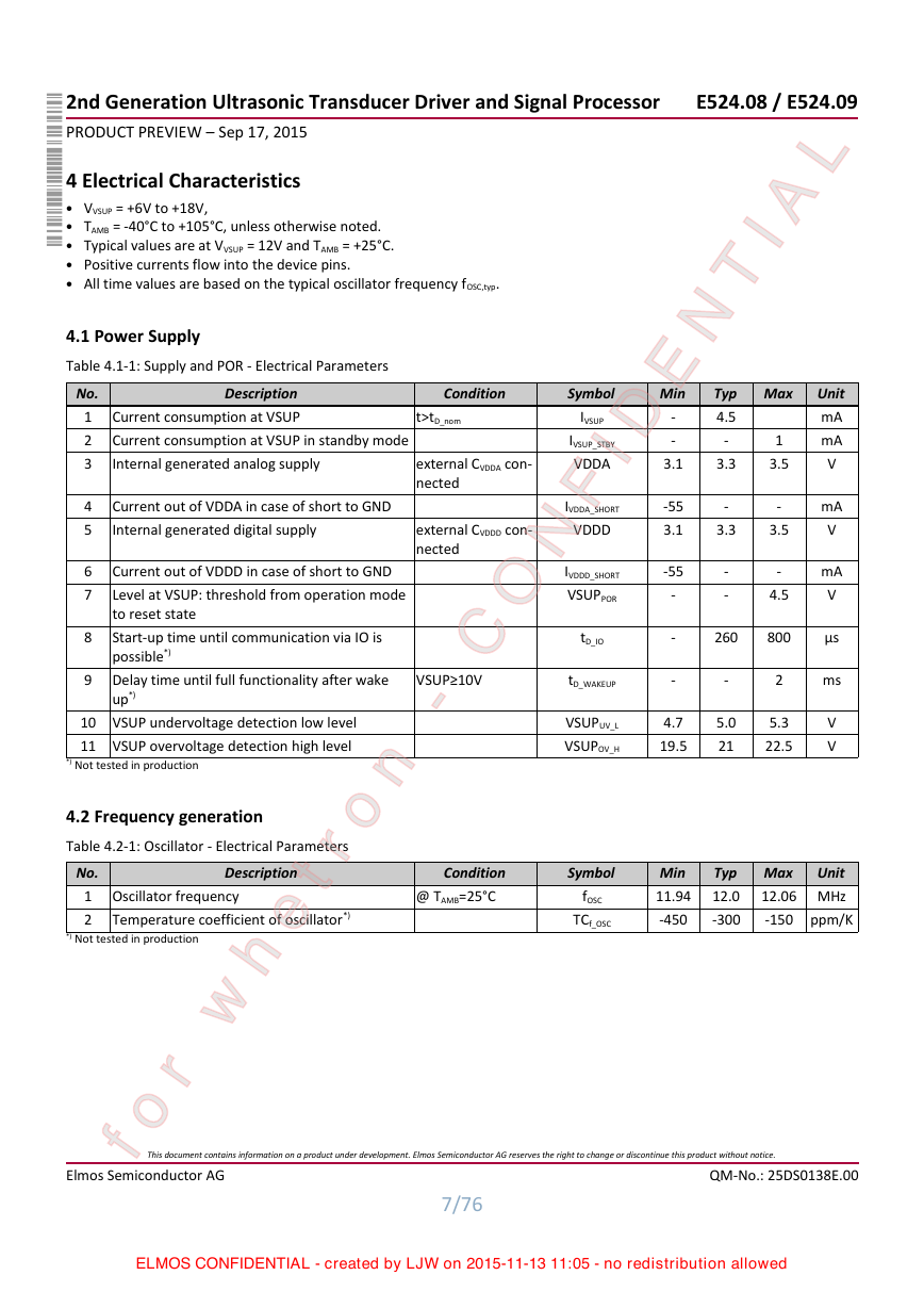
2nd Generation Ultrasonic Transducer Driver and Signal Processor PRODUCT PREVIEW – Sep 17, 2015 E524.08 / E524.09 L TIA N E FID N Typ Max 4.5 - 3.3 IVDDA_SHORT VDDD Min - - 3.1 IVSUP_STBY VDDA Symbol -55 3.1 - 3.3 IVSUP IVDDD_SHORT VSUPPOR -55 - - - 1 3.5 - 3.5 - 4.5 tD_IO tD_WAKEUP VSUPUV_L VSUPOV_H - - 4.7 19.5 260 800 - 5.0 21 2 5.3 22.5 Unit mA mA V mA V mA V μs ms V V Condition @ TAMB=25°C Symbol fOSC TCf_OSC Min 11.94 -450 Typ Max 12.0 -300 Unit 12.06 MHz ppm/K -150 4 Electrical Characteristics • VVSUP = +6V to +18V, • TAMB = -40°C to +105°C, unless otherwise noted. • Typical values are at VVSUP = 12V and TAMB = +25°C. • Positive currents flow into the device pins. • All time values are based on the typical oscillator frequency fOSC,typ. 4.1 Power Supply Table 4.1-1: Supply and POR - Electrical Parameters No. 1 2 3 Description Current consumption at VSUP Current consumption at VSUP in standby mode Internal generated analog supply Condition t>tD_nom external CVDDA con- nected 4 5 6 7 8 9 Current out of VDDA in case of short to GND Internal generated digital supply Current out of VDDD in case of short to GND Level at VSUP: threshold from operation mode to reset state Start-up time until communication via IO is possible*) Delay time until full functionality after wake up*) external CVDDD con- nected O VSUP≥10V n - C 10 VSUP undervoltage detection low level 11 VSUP overvoltage detection high level *) Not tested in production Description *) Not tested in production 4.2 Frequency generation Table 4.2-1: Oscillator - Electrical Parameters No. 1 Oscillator frequency 2 Temperature coefficient of oscillator*) o etr h r w fo Elmos Semiconductor AG This document contains information on a product under development. Elmos Semiconductor AG reserves the right to change or discontinue this product without notice. 7/76 QM-No.: 25DS0138E.00 ELMOS CONFIDENTIAL - created by LJW on 2015-11-13 11:05 - no redistribution allowed
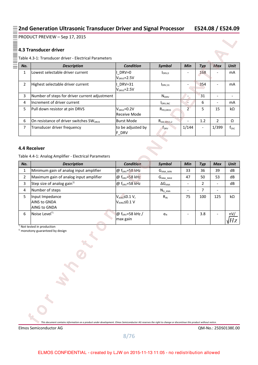
L - - IDRV,31 354 Min - Symbol IDRV,0 Typ Max 168 TIA N E FID N NIDRV IDRV,INC RPD,DRVS 31 6 5 - - 15 RSW,DRV1,2 1.2 - - - - 2 - 2 1/399 fDRV 1/144 Symbol GANA_MIN GANA_MAX ΔGANA NG_ANA RIN Min 33 47 - - 75 Typ Max 39 36 53 50 2 - 7 - 125 100 Unit mA mA - mA kΩ Ω fOSC Unit dB dB dB kΩ eN - 3.8 - nV/ I_DRV=0 VDRVS=2.5V I_DRV=31 VDRVS=2.5V VDRVS=0.2V Receive Mode Burst Mode to be adjusted by F_DRV O Condition @ fDRV=58 kHz @ fDRV=58 kHz @ fDRV=58 kHz n - C VAINS≤0.1 V, VAING≤0.1 V @ fDRV=58 kHz / max gain 4.3 Transducer driver Table 4.3-1: Transducer driver - Electrical Parameters No. 1 2 3 4 5 Lowest selectable driver current Highest selectable driver current Number of steps for driver current adjustment Increment of driver current Pull down resistor at pin DRVS 6 On resistance of driver switches SWDRVX 7 Transducer driver frequency 4.4 Receiver Table 4.4-1: Analog Amplifier - Electrical Parameters Description No. 1 Minimum gain of analog input amplifier 2 Maximum gain of analog input amplifier 3 4 5 Step size of analog gain1) Number of steps Input Impedance AINS to GNDA AING to GNDA Noise Level*) 6 *) Not tested in production 1) monotony guaranteed by design o etr h r w fo Elmos Semiconductor AG 2nd Generation Ultrasonic Transducer Driver and Signal Processor PRODUCT PREVIEW – Sep 17, 2015 E524.08 / E524.09 Description Condition This document contains information on a product under development. Elmos Semiconductor AG reserves the right to change or discontinue this product without notice. 8/76 QM-No.: 25DS0138E.00 ELMOS CONFIDENTIAL - created by LJW on 2015-11-13 11:05 - no redistribution allowed
分享到:
收藏