User and installation manual
HTL40 LINK
.
0
0
0
0
9
4
0
6
4
D
O
C
.
.
�
�������
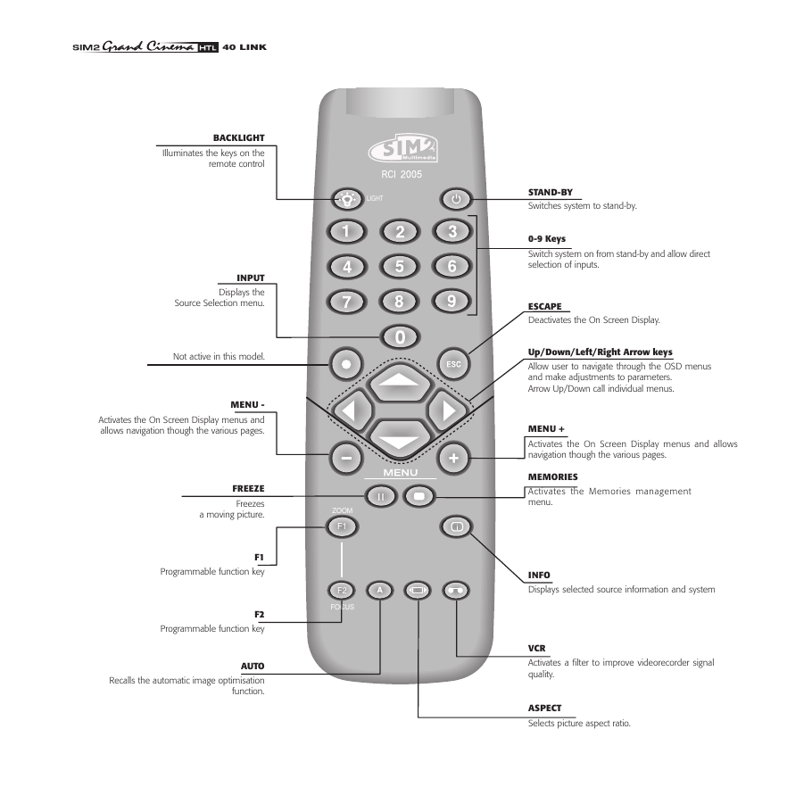
BACKLIGHT
Illuminates the keys on the
remote control
INPUT
Displays the
Source Selection menu.
Not active in this model.
MENU -
Activates the On Screen Display menus and
allows navigation though the various pages.
FREEZE
Freezes
a moving picture.
F1
Programmable function key
F2
Programmable function key
ZOOM
F1
F2
FOCUS
AUTO
Recalls the automatic image optimisation
function.
LIGHT
STAND-BY
Switches system to stand-by.
0-9 Keys
Switch system on from stand-by and allow direct
selection of inputs.
ESCAPE
Deactivates the On Screen Display.
Up/Down/Left/Right Arrow keys
Allow user to navigate through the OSD menus
and make adjustments to parameters.
Arrow Up/Down call individual menus.
MENU +
Activates the On Screen Display menus and allows
navigation though the various pages.
MEMORIES
Activates the Memories management
menu.
INFO
Displays selected source information and system
VCR
Activates a filter to improve videorecorder signal
quality.
ASPECT
Selects picture aspect ratio.
�
1 INTRODUCTION
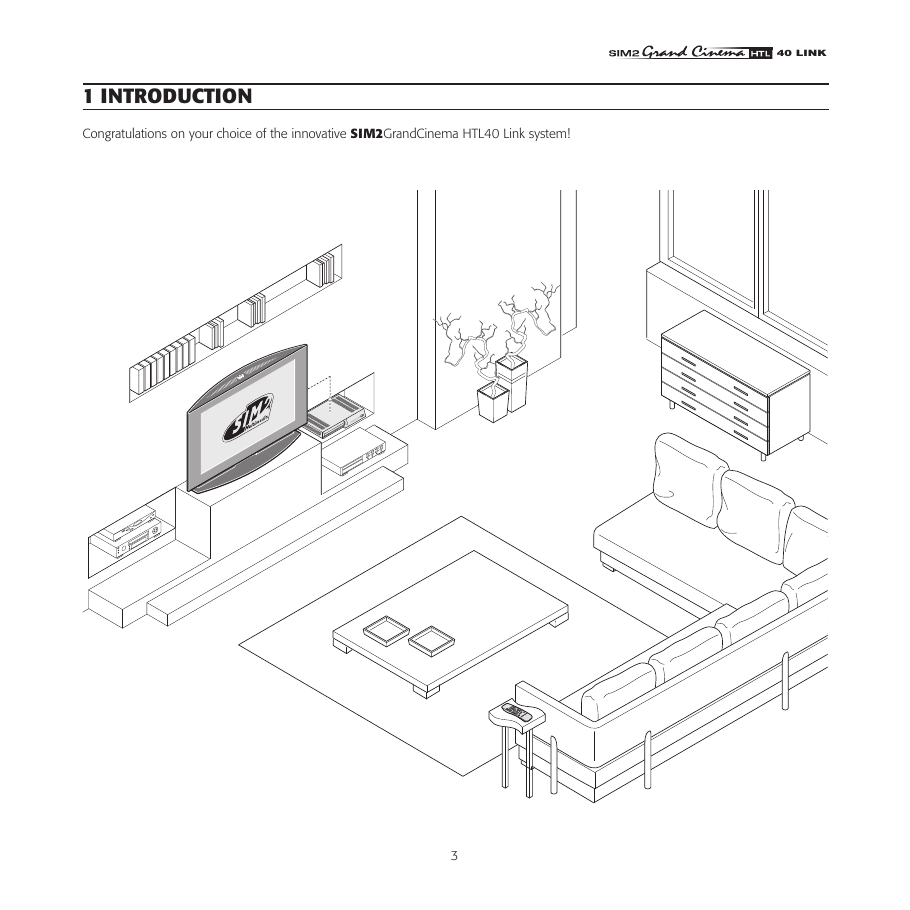
Congratulations on your choice of the innovative SIM2GrandCinema HTL40 Link system!
�������
DIGIOPTIC ™ IMAGE PROCESSOR
ON
OFF
3
�
�������
The new HTL40 LINK flat screen offers the ideal combination
between top TFT-LCD technology and an expert system for digital
processing of video signals.
The signal processing capabilities of the Image Processor ensure
optimum reproduction of a broad range of input signals, from in-
terlaced video to high definition and graphics.
Your HTL40 LINK system is composed of two refined and elegant
units. The 40’’ screen reflects the state of the art of TFT-LCD tech-
nology, with 1366x768 pixel resolution and the ability to display
up to 16.7 million colours. The DigiOpticTM Image Processor
video signal processing unit assures the acquisition of a very broad
range of different video signals, while simultaneously providing the
processing power needed to produce sharp, detailed pictures with
bright natural colours.
Conversion of interlaced video signals to progressive signals by
means of prestigious DCDi™ technology produces fluid, natural
images free of artifacts such as flicker and stairstepping on diago-
nals.
Faithful reproduction of signals at higher resolutions (such as high
definition video and graphics) occurs without loss of information or
reduction of image sharpness thanks to the processor’s high pixel
rate signal acquisition capabilities.
The two units are interconnected by means of a single cable con-
taining three fibre optic cores. The fibre optic cores allow the digital
signal to be transmitted from the DigiOptic™ Image Processor to the
screen and control signals to be transmitted in both directions.
Thanks to the flexibility and reduced diameter of the fibre optic cable,
the two units can be sited in the room in a totally independent man-
ner (distances of up to 500 metres), thereby ensuring that they will
fit perfectly into the layout of your home theatre room.
A very broad range of different video signals can be connected to
the DigiOptic™ Image Processor, which, since it is separate from the
screen, can be placed anywhere in your room without detracting
from the elegant styling and clean lines of the screen unit.
The large number of inputs available on the DigiOptic™ Image
Processor (2 Composite Video inputs, 2 S-Video inputs, up to 4
Component or RGB inputs, 2 graphic RGB inputs, 1 DVI-D input,
1 HDMI™ input), ensures the system supports and processes a
wide range of video signals from various sources: DVD players,
VCRs, satellite and terrestrial receivers, computers, game consoles,
video cameras, etc.
In addition, the specific type of signal processing makes it possible to
eliminate the swirl effects that can sometimes mar the performance
of LCD screens when displaying moving images.
All image adjustments can be performed from the remote control
with the aid of the On Screen Display; alternatively, the unit can be
controlled by from a home automation system through the serial
port.
Besides the usual checks, the Quality Control department
also runs additional statistical tests before shipment.
Therefore the packing may show signs of having been
opened.
DCDi is a registered trademark of Faroudja, a division of Genesis Microchip, Inc.
DigiOptic™ is a registered trademark of SIM2.
HDMI, the HDMI logo and the expression High-Definition Multimedia Interface are trade marks or registered marks of HDMI licensing
LLC
4
�
2 IMPORTANT SAFETY INSTRUCTIONS
�������
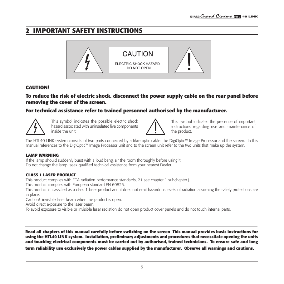
CAUTION!
To reduce the risk of electric shock, disconnect the power supply cable on the rear panel before
removing the cover of the screen.
For technical assistance refer to trained personnel authorised by the manufacturer.
This symbol indicates the possible electric shock
hazard associated with uninsulated live components
inside the unit.
This symbol indicates the presence of important
instructions regarding use and maintenance of
the product.
The HTL40 LINK system consists of two parts connected by a fibre optic cable: the DigiOptic™ Image Processor and the screen. In this
manual references to the DigiOptic™ Image Processor unit and to the screen unit refer to the two units that make up the system.
LAMP WARNING
If the lamp should suddenly burst with a loud bang, air the room thoroughly before using it.
Do not change the lamp: seek qualified technical assistance from your nearest Dealer.
CLASS 1 LASER PRODUCT
This product complies with FDA radiation performance standards, 21 see chapter 1 subchapter j.
This product complies with European standard EN 60825.
This product is classified as a class 1 laser product and it does not emit hazardous levels of radiation assuming the safety protections are
in place.
Caution! invisible laser beam when the product is open.
Avoid direct exposure to the laser beam.
To avoid exposure to visible or invisible laser radiation do not open product cover panels and do not touch internal parts.
Read all chapters of this manual carefully before switching on the screen This manual provides basic instructions for
using the HTL40 LINK system. Installation, preliminary adjustments and procedures that necessitate opening the units
and touching electrical components must be carried out by authorised, trained technicians. To ensure safe and long
term reliability use exclusively the power cables supplied by the manufacturer. Observe all warnings and cautions.
5
�
�
�������
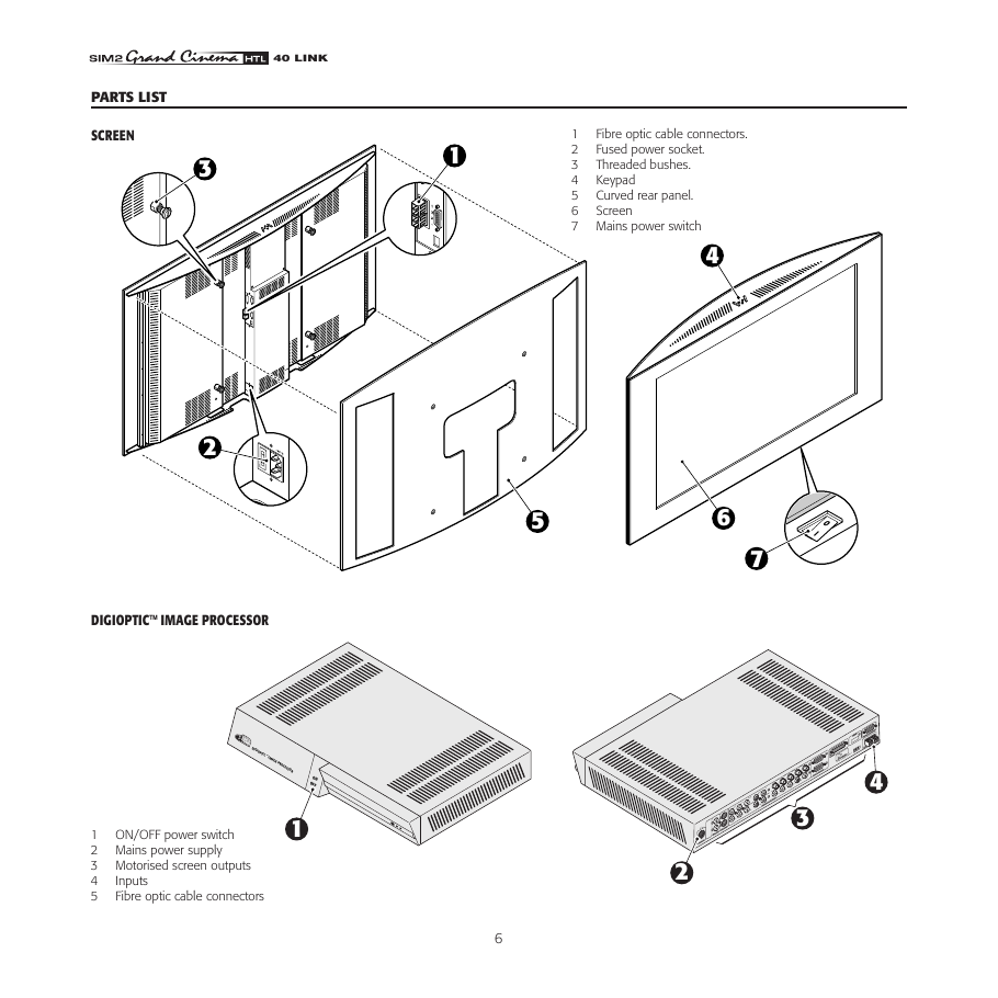
PARTS LIST
SCREEN
�
�
DIGIOPTIC™ IMAGE PROCESSOR
���������������������������
��
���
�
1 ON/OFF power switch
2 Mains power supply
3 Motorised screen outputs
4
5
Inputs
Fibre optic cable connectors
Fused power socket.
Threaded bushes.
1 Fibre optic cable connectors.
2
3
4 Keypad
5 Curved rear panel.
6
7 Mains power switch
Screen
�
�
�
�
�
�
�����
��
��
�
��
�����
������� �� ������ ������
���������
�
�
�
�
����
����
����
����
���������� ��
���
���
����
����
�
�
�
�
�
������������� ���
����
����
����
����
���
���
����
����
�
�
�������
�
�
�����
�����
�����
�
6
�
�
�
�
��������� �������
������������������
�
�
• Read this manual carefully and keep it in a safe place
for future consultation.
This manual contains important information on how to install
and use this equipment correctly. Before using the equipment,
read the safety prescriptions and instructions carefully. Keep the
manual for future consultation.
• Do not touch internal parts of the units.
The units contain electrical parts carrying high voltages and
operating at high temperatures. Do not remove the cover from
the units, refer to qualified service personnel for all repair and
maintenance requirements. The warranty will be automatically
invalidated if the cover is removed from the units.
• Power supply disconnect device.
The device for disconnecting the units from the mains power
supply is constituted by the power cable plug. Ensure that the
power cable plugs and the electrical mains socket outlets are
easily accessible during installation operations. To disconnect the
units from the electric power supply, pull the plug to remove it
from the socket outlet. Do not pull the power cable.
• Connect the unit only to the type of power supply indi-
cated.
Connect the units to a mains electrical supply with rated voltage of
between 120-240 Vac, 50/60 Hz and equipped with a protective
earth connection. If you are unsure of the type of mains power
supply in your home, consult a qualified electrician. Ensure that
the power draw of the units is commensurate with the rating of
the electrical socket outlets and any extension cables that are
used. For the DigiOptic™ Image Processor use exclusively the
power supply unit provided or an alternative power supply unit
expressly approved by SIM2.
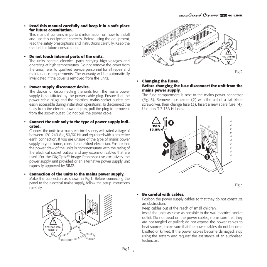
• Connection of the units to the mains power supply.
Make the connection as shown in Fig.1. Before connecting the
panel to the electrical mains supply, follow the setup instructions
carefully.
Fig.1
7
� �
�������
Fig.2
• Changing the fuses.
Before changing the fuse disconnect the unit from the
mains power supply.
The fuse compartment is next to the mains power connector
(Fig. 3). Remove fuse carrier (2) with the aid of a flat blade
screwdriver, then change fuse (3). Insert a new spare fuse (4).
Use only T 3.15A H fuses.
�
�����
���������
�
�
�
Fig.3
• Be careful with cables.
Position the power supply cables so that they do not constitute
an obstruction.
Keep cables out of the reach of small children.
Install the units as close as possible to the wall electrical socket
outlet. Do not tread on the power cables, make sure that they
are not tangled or pulled; do not expose the power cables to
heat sources; make sure that the power cables do not become
knotted or kinked. If the power cables become damaged, stop
using the system and request the assistance of an authorised
technician.
�
• Never look directly at the projection lamp.
Never look directly at the lamp through the ventilation opening
when the unit is switched on. Risk of eyesight impairment. Ensure
also that children do not look directly at the lamp.
• Position the unit on a stable surface.
The screen must be positioned on a suitable stable surface or
be installed using a bracket for fixed ceiling or wall installation.
Never use the screen by resting it on either of its sides or on the
rear panel.
• Do not insert objects through the openings in the
unit.
Make sure that no objects are inserted inside the units. If this
should occur, disconnect the unit from the power supply im-
mediately and call an authorised technician.
�������
• Disconnect the unit from the mains power supply in the
event of electrical storms and when not in use.
To avoid damage that could be caused by lightning striking in
the vicinity of your home, disconnect the units in the event of
electrical storms or when the system will remain unused for
prolonged periods.
• Avoid contact with liquids and exposure to humidity.
Do not use the units near water (sinks, tanks, etc.); do not place
objects containing liquids on top of or near the units and do not
expose then to rain, humidity, dripping water or spray; do not
use water or liquid detergents to clean the units.
• Prevent the units from overheating.
Do not obstruct ventilation openings. Do not place the units near
heat sources such as heaters, radiators or other devices that
generate heat (including amplifiers). Do not position the units
in confined, poorly ventilated places (bookcase, shelves, etc.).
8
�


 2023年江西萍乡中考道德与法治真题及答案.doc
 2012年重庆南川中考生物真题及答案.doc
 2013年江西师范大学地理学综合及文艺理论基础考研真题.doc
 2020年四川甘孜小升初语文真题及答案I卷.doc
 2020年注册岩土工程师专业基础考试真题及答案.doc
 2023-2024学年福建省厦门市九年级上学期数学月考试题及答案.doc
 2021-2022学年辽宁省沈阳市大东区九年级上学期语文期末试题及答案.doc
 2022-2023学年北京东城区初三第一学期物理期末试卷及答案.doc
 2018上半年江西教师资格初中地理学科知识与教学能力真题及答案.doc
 2012年河北国家公务员申论考试真题及答案-省级.doc
 2020-2021学年江苏省扬州市江都区邵樊片九年级上学期数学第一次质量检测试题及答案.doc
 2022下半年黑龙江教师资格证中学综合素质真题及答案.doc