ARllCLES
LEGGED ROBOTS
Research on legged machines can lead to the construction of useful legged
vehicles and help us to understand
legged locomotion
in animals.
MARC H. RAIBERT
LEGGED MACHINES?
run, there are two serious reasons for ex-
the use of legs for locomotion. One is mobil-
WHY STUDY
Aside from the sheer thrill of creating machines that
actually
ploring
ity: There is a need for vehicles that can travel in
difficult
terrain, where existing vehicles cannot go.
Wheels excel on prepared surfaces such as rails and
roads, but perform poorly where the terrain
is soft
or uneven. Because of these limitations, only about
half the earth’s landmass is accessible to existing
wheeled and tracked vehicles, whereas a much
greater area can be reached by animals on foot. It
should be possible to build
go to the places that animals can now reach.
legged vehicles that can
One reason legs provide better mobility
in rough
is that they can use isolated footholds that
terrain
optimize support and traction, whereas a wheel re-
quires a continuous path of support. As a conse-
quence, a legged system can choose among the best
footholds in the reachable terrain; a wheel must ne-
gotiate the worst terrain. A ladder illustrates
point: Rungs provide
footholds that enable the as-
cent of legged systems, but the spaces between the
rungs prohibit
the ascent of wheeled systems.
this
With the exception of a few modifications.
Legged Robofs
sion of the author and The MIT Press.
tl~of Balance. 0 1986 by Marc H. Raibert. Reprinted by permis-
this article
is excerpted
from
Another advantage of legs is that they provide an
active suspension that decouples the path of the
body from the paths of the feet. The payload is free
to travel smoothly despite pronounced variations
in
the terrain. A legged system can also step over obsta-
cles. In principle,
the performance of legged vehicles
can, to a great extent, be independent of the detailed
roughness of the ground.
footholds, sense the terrain
The construction of useful legged vehicles de-
pends on progress in several areas of engineering
and science. Legged vehicles will need systems that
control joint motions, sequence the use of legs, mon-
itor and manipulate balance, generate motions to use
known
to find good foot-
holds, and calculate negotiable foothold sequences.
Most of these tasks are not well understood yet, but
research is under way. If this research is successful,
it will
that travel efficiently and quickly
in terrain where
softness, grade, or obstacles make existing vehicles
ineffective. Such vehicles will be useful in indus-
trial, agricultural, and military applications.
lead to the development of legged vehicles
The second reason for exploring
legged machines
is to gain a better understanding of human and ani-
mal locomotion. Slow-motion
replays re-
veal to us the large variety and complexity of ways
athletes can carry, swing, toss, glide, and otherwise
television
june 1986 Volume 29 Number 6
Communications of the ACM
499
�
Articles
is equally
propel their bodies through space, maintaining
orientation, balance, and speed as they go. Such per-
to professional athletes; be-
formance is not limited
impressive
havior at the local playgroun’d
from a mechanical engineering, sensory-motor
inte-
gration, or computational point of view. Animals
also demonstrate g.reat mobihty and agility. They
use their legs to move quickly and reliably
through
forest, swamp, marsh, and jungle, and from tree to
tree. Sometimes thsey move with great speed, often
with great efficiency.
is to build
for animal
locomotion
locomotion
the control prmciples
Despite the skill we apply in using our own legs
for locomotion, we are still at a primitive stage in
understanding
that underlie
walking and running. What control mechanisms do
animals use? One way to learn more about plausible
mechanisms
legged
machines. To the extent that an animal and a ma-
chine perform similar
tasks, their control
systems and mecha.nical structures must solve simi-
lar problems. By building machines, we can gain
new insights
into these problems, and learn about
possible solutions. Of particul.ar value is the rigor
required
that actually
work. The concrete theories and algorithms devel-
oped for such machines can guide biological
search by suggesting specific models for experimen-
tal testing and verification. This sort of interdisci-
plinary approach is already becoming popular
in
other areas where biology and robotics have a com-
mon ground, such as vision, speech, and manipula-
tion.
to build p:hysical machines
re-
ON LEGGED MACHINES
RESEARCH
The scientific study of legged locomotion began just
over a century ago when Leland Stanford, then gov-
ernor of California, commissioned Eadweard Muy-
bridge to find out whether or not a trotting horse left
the ground with all four feet at the same time. See
Table I for milestones in the development of legged
robots. Stanford had wagered that it never did. After
Muybridge proved him wrong with a set of stop-
motion photographs
ican in 1878, Muybridge went on to document
walking and rurming behavior of over 40 mammals,
including humans
still of considerable value and survive as a landmark
in locomotion
that appeared in Scientific Amer-
[24, 251. His photographic data are
the
research.
The study of machines
that walk also had its ori-
gin in Muybridge’s
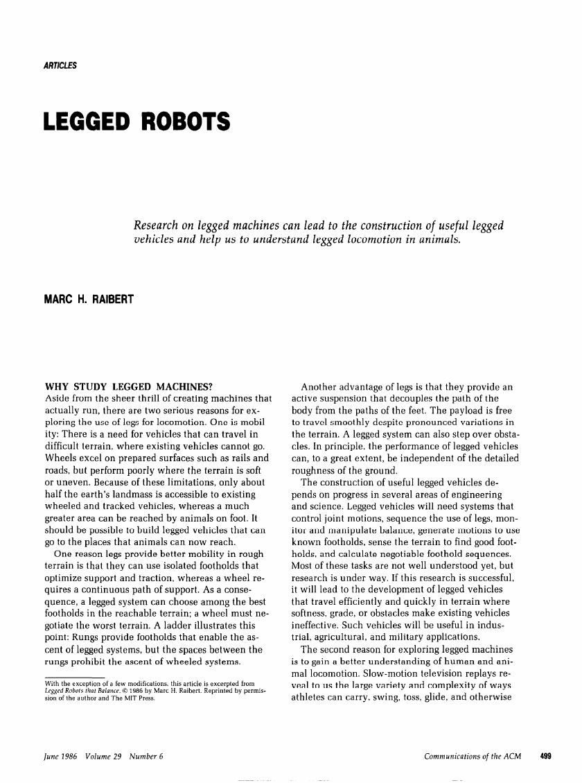
time. An early walking model
appeared in about 1870 [13]. It used a linkage to
move the body along a straight horizontal path while
the feet moved up and down to exchange support
during stepping (see Figure 1). The linkage was origi-
TABLE 1. Milestones in the Development of Legged Robots
1850 Chebyshev
1872 Muybridge
:
1893 Rygg
1946 ’ Wallace
1961 Space General
1963 Cannon, Higdon,
and Schaefer
Daaigns linkage usad in early
walking mechanism [13].
lkaS stop-motion photography to
document running animals.
Patents human-powered
mechanical horse.
Patents hopping tank with
reaction wheals that provide
: stability.
Eight-legged kinematic machine
walks in outdoor terrain [21].
i=ontrot system balances single,
j double, and limber inverted
-pendulums.
1968 Frank and h&Ghea simple digital logii controls
walking of Phony Pony.
1968 Mosher
1969 Bucyrus-Erie Co.
i977
kAcGhee
1977 Gurfinkel
1977 McMahon and
Greene
.
1980 Hfrose and
Vrnetani
1980 Kate
1980 Matsuoka
1981 Miura and
Shimoyama
1983 Gumerland
1983 Odetics
fSE quadruped truck climbs
railroad ties under control of
human driver.
Big Muskie, a 15,000-ton walking
dragline, is used for strip
mining. ft moves in soft terrain
at a speed of 900 ft./h. [35].
Digital computer coordinates leg
motions of hexapod walking
machine.
Hybrid computer controls
hexapod walker in USSR.
fluman runners set new speed
records on tuned track at
; Harvard. I& compliance is
; adjusted to mechanics of
.&
human leg.
&adrupad machina climbs stairs
and climbs over obstacles
[ using simple sensors. The leg
mechanism simplifies control.
fiydraulic biped walks with quasi-
‘
dynamic gait.
Mechanism balances in the plane
while hopping on one leg.
Walking biped balances actively in
three-dimensional space.
pexapod carries human rider.
Computer, hydraulics, and
human share computing task.
&alf-contained hexapod lifts and
moves back end of pickup
i +ruck [31].
the 80 or
nally designed by the famous Russian mathemati-
cian Chebyshev some years earlier. During
the task of
90 years that followed, workers viewed
building walking machines as the task of designing
linkages that would generate suitable stepping mo-
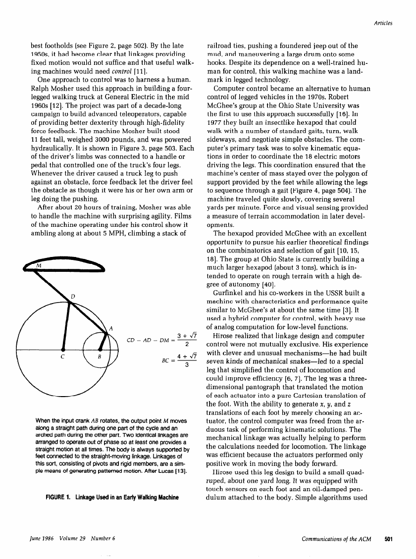
tions when driven by a source of power. Many de-
signs were proposed (e.g., [l, 21, 34, 36, 38]), but the
performance of such machines was limited by their
fixed patterns of motion, since they could not adjust
to variations
in the terrain by placing the feet on the
500
Communications of the ACM
lune 1986 Volume 29 Number 6
�
best footholds (see Figure 2, page 502). By the late
195Os, it had become clear that linkages providing
fixed motion would not suffice and that useful walk-
ing machines would need control [ll].
truck at General Electric
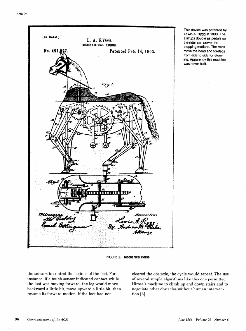
One approach to control was to harness a human.
Ralph Mosher used this approach in building a four-
legged walking
in the mid
1960s [12]. The project was part of a decade-long
campaign to build advanced teleoperators, capable
of providing better dexterity
through high-fidelity
force feedback. The machine Mosher built stood
11 feet tall, weighed 3000 pounds, and was powered
hydraulically.
It is shown in Figure 3, page 503. Each
of the driver’s
limbs was connected to a handle or
pedal that controlled one of the truck’s four legs.
Whenever
the driver caused a truck leg to push
against an obstacle, force feedback let the driver
feel
the obstacle as though it were his or her own arm or
leg doing the pushing.
After about 20 hours of training, Mosher was able
to handle the machine with surprising agility. Films
of the machine operating under his control show it
ambling along at about 5 MPH, climbing a stack of
CD=AD=DM=2
3 + v7
4+J7
Bc = 3
When the input crank AB rotates, the output point M moves
along a straight path during one part of the cycle and an
arched path during the other part. Two identical linkages are
arranged to operate out of phase so at least one provides a
straight motion at all times. The body is always supported by
feet connected to the straight-moving linkage. Linkages of
this sort, consisting of pivots and rigid members, are a sim-
ple means of generating patterned motion. After Lucas [ 131.
FIGURE 1. Linkage Used in an Early Walking Machine
Articles
ties, pushing a foundered
railroad
jeep out of the
mud, and maneuvering a large drum onto some
hooks. Despite its dependence on a well-trained
man for control,
mark in legged technology.
this walking machine was a land-
hu-
Computer control became an alternative
to human
in the 1970s. Robert
task was to solve kinematic equa-
the 18 electric motors
control of legged vehicles
McGhee’s group at the Ohio State University was
the first to use this approach successfully
[16]. In
1977 they built an insectlike hexapod that could
walk with a number of standard gaits, turn, walk
sideways, and negotiate simple obstacles. The com-
puter’s primary
tions in order to coordinate
driving
the legs. This coordination ensured that the
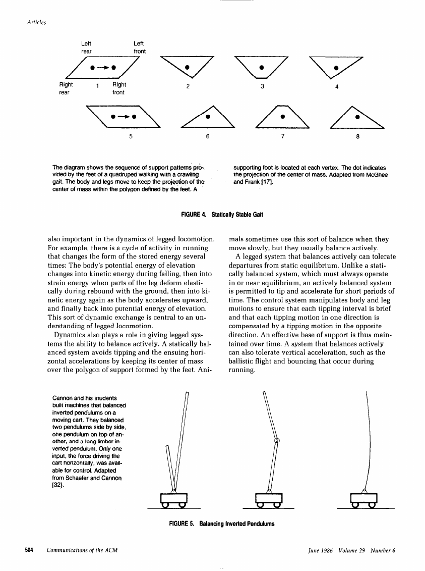
machine’s center of mass stayed over the polygon of
support provided by the feet while allowing
the legs
to sequence through a gait (Figure 4, page 504). The
machine traveled quite slowly, covering several
yards per minute. Force and visual sensing provided
a measure of terrain accommodation
in later devel-
opments.
to pursue his earlier
The hexapod provided McGhee with an excellent
findings
opportunity
on the combinatorics and selection of gait [lo, 15,
181. The group at Ohio State is currently building a
much larger hexapod (about 3 tons), which
tended to operate on rough terrain with a high de-
gree of autonomy
theoretical
is in-
[40].
Gurfinkel and his co-workers
in the USSR built a
machine with characteristics and performance quite
similar
used a hybrid computer
of analog computation
to McGhee’s at about the same time [3]. It
for control, with heavy use
for low-level
functions.
the control of locomotion and
[6, 71. The leg was a three-
that translated
Hirose realized that linkage design and computer
control were not mutually exclusive. His experience
had built
with clever and unusual mechanisms-he
seven kinds of mechanical snakes-led
to a special
leg that simplified
could improve efficiency
dimensional pantograph
of each actuator into a pure Cartesian translation of
the foot. With the ability
translations of each foot by merely choosing an ac-
tuator, the control computer was freed from the ar-
duous task of performing kinematic solutions. The
mechanical
to perform
the calculations needed for locomotion. The linkage
was efficient because the actuators performed only
positive work in moving the body forward.
linkage was actually helping
to generate x, y, and z
the motion
Hirose used this leg design to build a small quad-
ruped, about one yard long. It was equipped with
touch sensors on each foot and an oil-damped pen-
dulum attached to the body. Simple algorithms used
June 1986 Volume 29 Number 6
Communications of the ACM
501
�
This device was patented by
Lewis A. Rygg in 1893. The
stirrups double as pedak so
the rider can power the
stepping motions. The reins
move the head and forelegs
from side to side for steer-
ing. Apparently this machine
was never built.
Articles
110 Yew.)
-
L. A. BYQQ.
YEOEANIOAL H018E.
No. 49X,
7,
?A
Patented Feb. 14, L&n.
FIGURE 2. Mechanical Horse
the sensors to control
the actions of the feet. For
instance, if a touch sensor indicated contact while
the foot was moving forward,
the leg would move
backward a little b:it, move upward a little bit, then
resume its forward motion. If the foot had not
cleared the obstacle, the cycle would repeat. The use
of several simple algorithms
Hirose’s machine
negotiate other obstacles without human interven-
tion [6].
to climb up and down stairs and to
like this one permitted
502
Communications of the ACM
lune 1986 Volume 29 Number 6
�
These three walking machines, McGhee’s, Gurfin-
kel’s, and Hirose’s, represent a class called static
crawlers. Each differs in the details of construction
and in the computing
technology used for control,
but shares a common approach to balance and sta-
bility. Enough feet are kept on the ground to guaran-
tee a broad base of support at all times, and the body
and legs move to keep the center of mass over this
broad support base. The forward velocity
ficiently
ured into the stability calculation. Each of these ma-
chines has been used to study rough terrain
locomo-
tion in the laboratory
through experiments on ter-
rain sensing, gait selection, and selection of foothold
sequences. Several other machines that fall into this
class have been studied in the intervening
years, for
example, see [31] and [3i’].
low so that stored energy need not be fig-
is kept suf-
Articles
AND BALANCE
the behavior of a dynamic system, we
In order to predict
DYNAMICS
IMPROVE MOBILITY
We now consider the study of dynamic machines
that balance actively. This means that the legged
systems studied operate in a regime where the ve-
locities and kinetic energies of the masses are impor-
tant determinants of behavior.
and influence
must consider the energy stored in each mass and
spring as well as the geometric structure and config-
uration of the mechanism. Geometry and configura-
tion taken alone do not provide an adequate model
when a system moves with substantial speed or has
large mass. Consider, for example, a fast-moving ve-
hicle with
feet: It would
its center of mass too close to the front
tip over if it stopped suddenly.
The exchange of energy among its various forms is
This vehicle was developed
by Ralph Mosher at General
Electric in about 1966. The
human driver controlled the
machine with four handles
and pedals that were hy-
draulically connected to the
four legs. Photograph cour-
tesy of General Electric Re-
search and Development
Center.
FIGURE 3. Walking Truck
]une 1986 Volume 29 Number 6
Communications of the ACM
503
�
Articles
Left
rear
Left
front
Right
rear
1
Right
front
\--
\
\
0-o
\
5
6
7
a
The diagram shows the sequence of support patterns pr&
vided by the feet of a quadruped walking with a crawlfng
gait. The body and legs move to keep the projeotfon of the
center of mass within the polygon defined by the feet. A
supporting foot is located at each vertex. The dot indicates
the projection of the center of mass. Adapted from McGhee
and Frank [17].
FIGURE 4. Statically Stable Gait
mals sometimes use this sort of balance when they
move slowly, but they usually balance actively.
A legged system that balances actively can tolerate
departures from static equilibrium. Unlike a stati-
cally balanced system, which must always operate
in or near equilibrium,
an actively balanced system
is permitted
to tip and accelerate for short periods of
time. The control system manipulates body and leg
motions to ensure that each tipping
is brief
and that each tipping motion
compensated by a tipping motion
direction. An effective base of support is thus main-
tained over time. A system that balances actively
can also tolerate vertical acceleration, such as the
ballistic
running.
is
in the opposite
flight and bouncing
that occur during
interval
in one direction
in the dynamics of legged locomotion.
also important
For example, there is a cycle of activity
in running
that changes the form of the stored energy several
times: The body’s potential energy of elevation
changes into kinetic energy during
strain energy when parts of the leg deform elasti-
cally during rebound with
the ground, then into ki-
netic energy again as the body accelerates upward,
and finally back into potential energy of elevation.
This sort of dynamic exchange is central to an un-
derstanding of legged locomotion.
then into
falling,
Dynamics also plays a role in giving legged sys-
to balance actively. A statically bal-
tems the ability
anced system avoids tipping and the ensuing hori-
zontal accelerations by keeping its center of mass
over the polygon of support formed by the feet. Ani-
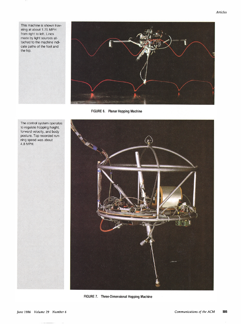
Cannon and his students
built machines that balanced
inverted pendulums on a
moving cart. They balanced
two pendulums side by side,
ohe pendulum on top of an-
other, and a long limber in-
verted pendulum. Only one
input, the force driving the
cart horizontally, was avail-
able for control. Adapted
from Schaefer and Cannon
1321.
FIGURE 5. Balancing Inverted Pendulums
504
Communications of the ,4CM
Iune 1986 Volume 29 Number 6
�
This machine
eling at about
ftom right to 11
made by light
tached to the
cate paths of
the hip.
is shown trav-
I .75 MPH
eft. Lines
sources at-
machine indi-
the foot and
The control s
to regulate hr
forward vekx
posture. Top
ning speed v\I
4.8 MPH.
)ystem operates
opping height,
:ity, and body
recorded run-
ras about
FIGURE 6. Planar Hopping Machine
FIGURE 7. Three-Dimensional Hopping Machine
]une 1986 Volume 29 Number 6
Communications of the ACM
505
�
Articles
Two hydraulic cylin-
ders at 90” control
hip angles; servo
-,
valves used for pre-
cise positroning
Springs augment 7
lifting force and min-
imize loading on
knee components
Hydraulic accumula-
tor reduces pres-
sure fluctuations
and minimizes re-
quired size of sup-
Ben Brown and 1 had this
early concept
for a one
legged hopping machine
that was to operate in three
dimensions. The design
never left the drawing
board.
cylin-
Hydraulic/air
der acts in series with
spring to extend
le
Valve for exten-
Pivot for lateral
Wires/cables hold knee “vertical”
Gears in knee joint keep angles
legs
ual for upper and lower
Tapered
for minimum weight
(stepped)
leg
FIGURE 8. Design for Three-Dimensional Hopping Machine
The ability of an actively balanced system to de-
relaxes the rules gov-
part from static equilibrium
erning how legs can be used for support, which
in
turn leads to improved mobihty. For example, if a
legged system can tolerate tipping,
then it can posi-
tion its feet far from the center of mass in order to
use widely separated or erratically placed footholds.
If it can remain upright with a small base of support,
then it can travel where obstructions are closely
spaced or where the path of firm support is narrow.
support also con-
The ability
tributes
to mobility by allowing a system to move all
its legs to new footholds at one time, to jump onto or
over obstacles, and to use short periods of ballistic
flight
narrow-base and intermittent
crease the types of terrain a legged system can nego-
tiate. Animals
travel quickly on di.fficult
will have to balance actively,
move with animallike mobility and speed.
routinely exploit active balance to
legged vehicles
to use
support generally
for increased speed. These abilities
to tolerate intermittent
too, if they are to
terrain;
in-
BALANCE
RESEARCH ON ACTIVE
The first machines that balanced actively were auto-
matically controlled
knows that a human can balance a broom on a
finger with relative ease. Why not use automatic
inverted pendulums. Everyone
the first to do so. In
to build a broom that can balance itself?
control
Claude Shannon was probably
1951 he used the parts from an erector set to build a
machine that balanced an inverted pendulum atop a
small powered truck. The truck drove back and
forth in response to the tipping movements of the
pendulum, as sensed by a pair of switches at its
base. In order to move from one place to another,
the truck first had to drive away from the goal to
unbalance
toward the goal; in order
to balance again at the destination,
past the destination until
upright with no forward velocity,
to the goal.
the pendulum was again
then moved back
the truck moved
the pendulum
At Shannon’s urging, Robert Cannon and two of
his students at Stanford University set about demon-
strating controllers
that balanced two pendulums at
once. In one case, the pendulums were mounted
side by side on the cart, and in the other, they
were mounted one on top of the other (Figure 5,
page 504). Cannon’s group was interested
in the
single-input multiple-output
problem and in the
limitations of achievable balance: How could they
use the single force that drove the cart’s motion to
control
the angles of two pendulums as well as the
position of the cart? How far from balance could the
system deviate before it was impossible
to
to return
Communications of the ACM
/we 1986 Volume 29 Number 6
�



 2023年江西萍乡中考道德与法治真题及答案.doc
 2012年重庆南川中考生物真题及答案.doc
 2013年江西师范大学地理学综合及文艺理论基础考研真题.doc
 2020年四川甘孜小升初语文真题及答案I卷.doc
 2020年注册岩土工程师专业基础考试真题及答案.doc
 2023-2024学年福建省厦门市九年级上学期数学月考试题及答案.doc
 2021-2022学年辽宁省沈阳市大东区九年级上学期语文期末试题及答案.doc
 2022-2023学年北京东城区初三第一学期物理期末试卷及答案.doc
 2018上半年江西教师资格初中地理学科知识与教学能力真题及答案.doc
 2012年河北国家公务员申论考试真题及答案-省级.doc
 2020-2021学年江苏省扬州市江都区邵樊片九年级上学期数学第一次质量检测试题及答案.doc
 2022下半年黑龙江教师资格证中学综合素质真题及答案.doc