COMSOL
Multiphysics ™
M
E
M
S
M
o
d
u
l
e
M
n
i
i
c
o
u
r
s
e
V E R S I O N 3 . 3
�
How to contact COMSOL:
Benelux
COMSOL BV
Röntgenlaan 19
2719 DX Zoetermeer
The Netherlands
Phone: +31 (0) 79 363 4230
Fax: +31 (0) 79 361 4212
info@femlab.nl
www.femlab.nl
Denmark
COMSOL A/S
Diplomvej 376
2800 Kgs. Lyngby
Phone: +45 88 70 82 00
Fax: +45 88 70 80 90
info@comsol.dk
www.comsol.dk
Finland
COMSOL OY
Lauttasaarentie 52
FIN-00200 Helsinki
Phone: +358 9 2510 400
Fax: +358 9 2510 4010
info@comsol.fi
www.comsol.fi
France
COMSOL France
WTC, 5 pl. Robert Schuman
F-38000 Grenoble
Phone: +33 (0)4 76 46 49 01
Fax: +33 (0)4 76 46 07 42
info@comsol.fr
www.comsol.fr
Germany
FEMLAB GmbH
Berliner Str. 4
D-37073 Göttingen
Phone: +49-551-99721-0
Fax: +49-551-99721-29
info@femlab.de
www.femlab.de
Italy
COMSOL S.r.l.
Via Vittorio Emanuele II, 22
25122 Brescia
Phone: +39-030-3793800
Fax: +39-030-3793899
info.it@comsol.com
www.it.comsol.com
Norway
COMSOL AS
Søndre gate 7
NO-7485 Trondheim
Phone: +47 73 84 24 00
Fax: +47 73 84 24 01
info@comsol.no
www.comsol.no
Sweden
COMSOL AB
Tegnérgatan 23
SE-111 40 Stockholm
Phone: +46 8 412 95 00
Fax: +46 8 412 95 10
info@comsol.se
www.comsol.se
Switzerland
FEMLAB GmbH
Technoparkstrasse 1
CH-8005 Zürich
Phone: +41 (0)44 445 2140
Fax: +41 (0)44 445 2141
info@femlab.ch
www.femlab.ch
United Kingdom
COMSOL Ltd.
Studio G8 Shepherds Building
Rockley Road
London W14 0DA
Phone:+44-(0)-20 7348 9000
Fax: +44-(0)-20 7348 9020
info.uk@comsol.com
www.uk.comsol.com
United States
COMSOL, Inc.
1 New England Executive Park
Suite 350
Burlington, MA 01803
Phone: +1-781-273-3322
Fax: +1-781-273-6603
COMSOL, Inc.
1100 Glendon Avenue, 17th Floor
Los Angeles, CA 90024
Phone: +1-310-689-7250
Fax: +1-310-689-7527
COMSOL, Inc.
744 Cowper Street
Palo Alto, CA 94301
Phone: +1-650-324-9935
Fax: +1-650-324-9936
info@comsol.com
www.comsol.com
For a complete list of international
representatives, visit
www.comsol.com/contact
Company home page
www.comsol.com
COMSOL user forums
www.comsol.com/support/forums
COMSOL Multiphysics MEMS Module Minicourse
© COPYRIGHT 1994–2006 by COMSOL AB. All rights reserved
Patent pending
The software described in this document is furnished under a license agreement. The software may be used
or copied only under the terms of the license agreement. No part of this manual may be photocopied or
reproduced in any form without prior written consent from COMSOL AB.
COMSOL, COMSOL Multiphysics, and COMSOL Script are trademarks of COMSOL AB.
Other product or brand names are trademarks or registered trademarks of their respective holders.
Version:
September 2006
COMSOL 3.3
�
C O N T E N T S
Preface
Solving Electro-Thermo-Mechanical Problems
2
3
Microresistor Beam
4
Introduction . . . . . . . . . . . . . . . . . . . . . . . . 4
Model Definition . . . . . . . . . . . . . . . . . . . . . . . 4
Results and Discussion. . . . . . . . . . . . . . . . . . . . . 5
Modeling in COMSOL Multiphysics . . . . . . . . . . . . . . . . 6
Modeling Using the Graphical User Interface . . . . . . . . . . . . 7
Solving Piezoelectric Problems
22
A Piezoelectric Shear Actuated Beam
23
Introduction . . . . . . . . . . . . . . . . . . . . . . . . 23
Model Definition . . . . . . . . . . . . . . . . . . . . . . . 23
Results. . . . . . . . . . . . . . . . . . . . . . . . . . . 25
Modeling in COMSOL Multiphysics . . . . . . . . . . . . . . . . 26
References . . . . . . . . . . . . . . . . . . . . . . . . . 27
Modeling Using the Graphical User Interface . . . . . . . . . . . . 27
Eigenfrequency Analysis . . . . . . . . . . . . . . . . . . . . 32
Frequency-Response Analysis . . . . . . . . . . . . . . . . . . 33
Appendix: Geometry Modeling . . . . . . . . . . . . . . . . . 35
Low-Voltage Electroosmotic Micropump
38
Introduction . . . . . . . . . . . . . . . . . . . . . . . . 38
Model Definition . . . . . . . . . . . . . . . . . . . . . . . 41
Results and Discussion. . . . . . . . . . . . . . . . . . . . . 42
Modeling in COMSOL Multiphysics . . . . . . . . . . . . . . . . 45
References . . . . . . . . . . . . . . . . . . . . . . . . . 46
Modeling Using the Graphical User Interface . . . . . . . . . . . . 46
Appendix—Geometry Modeling . . . . . . . . . . . . . . . . . 54
C O N T E N T S | i
�
ii | C O N T E N T S
�
M E M S M o d u l e M i n i c o u r s e
| 1
�
Preface
Mathematical modeling has become a very important part of the research and
development work in engineering and science. Retaining a competitive edge requires
a fast path between ideas and prototypes, and in this regard mathematical modeling
and simulation provide a valuable shortcut for understanding both qualitative and
quantitative aspects of scientific and engineering design.
This minicourse gives you an introduction into the modeling of microscale systems
using COMSOL Multiphysics and the MEMS Module. It takes you though several
fields of science commonly encountered when modeling MEMS: electrical and
structural problems, piezoelectricity, and microfluidics. You do not require any prior
expertise in mathematical modeling or COMSOL Multiphysics in order to find it
rewarding.
Enjoy your modeling!
The COMSOL team
2 | M E M S M O D U L E M I N I C O U R S E
�
Solving Electro-Thermo-Mechanical
Problems
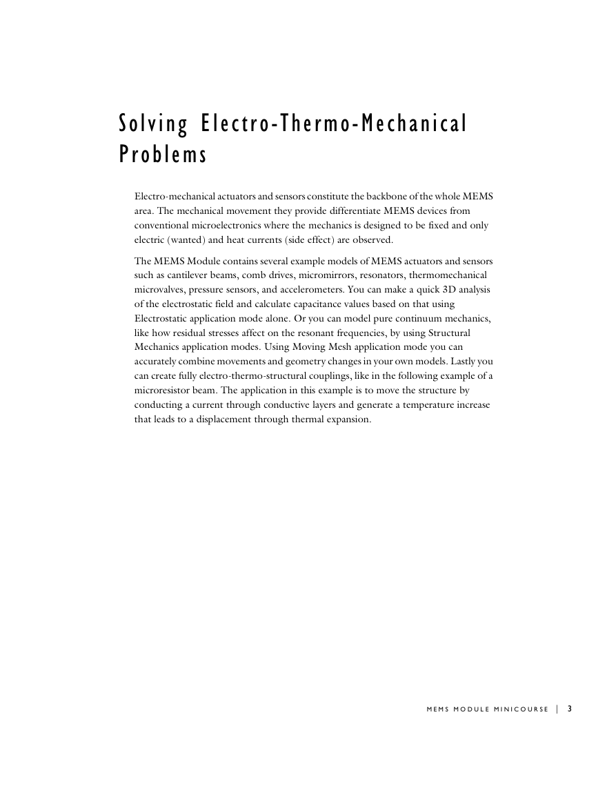
Electro-mechanical actuators and sensors constitute the backbone of the whole MEMS
area. The mechanical movement they provide differentiate MEMS devices from
conventional microelectronics where the mechanics is designed to be fixed and only
electric (wanted) and heat currents (side effect) are observed.
The MEMS Module contains several example models of MEMS actuators and sensors
such as cantilever beams, comb drives, micromirrors, resonators, thermomechanical
microvalves, pressure sensors, and accelerometers. You can make a quick 3D analysis
of the electrostatic field and calculate capacitance values based on that using
Electrostatic application mode alone. Or you can model pure continuum mechanics,
like how residual stresses affect on the resonant frequencies, by using Structural
Mechanics application modes. Using Moving Mesh application mode you can
accurately combine movements and geometry changes in your own models. Lastly you
can create fully electro-thermo-structural couplings, like in the following example of a
microresistor beam. The application in this example is to move the structure by
conducting a current through conductive layers and generate a temperature increase
that leads to a displacement through thermal expansion.
M E M S M O D U L E M I N I C O U R S E | 3
�
Microresistor Beam
Introduction
This example illustrates the ability to couple thermal, electrical, and structural analysis
in one model. This particular application moves a beam by passing a current through
it; the current generates heat, and the temperature increase leads to displacement
through thermal expansion. The model estimates how much current and increase in
temperature are necessary to displace the beam.
Although the model involves rather simple 3D geometry and straightforward physics,
it provides a good example of multiphysics modeling because it contains several appli-
cation modes added incrementally to the model. Note that this model of a microresis-
tor beam also appears in the companion MEMS Module Model Library in the
Actuators Models folder under the name micro_beam3d.
Model Definition
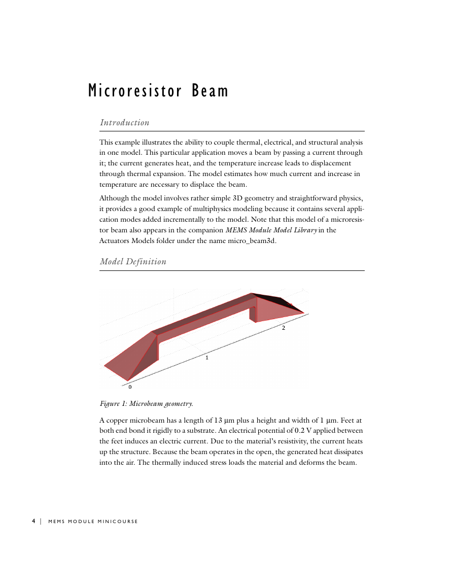
Figure 1: Microbeam geometry.
A copper microbeam has a length of 13 µm plus a height and width of 1 µm. Feet at
both end bond it rigidly to a substrate. An electrical potential of 0.2 V applied between
the feet induces an electric current. Due to the material’s resistivity, the current heats
up the structure. Because the beam operates in the open, the generated heat dissipates
into the air. The thermally induced stress loads the material and deforms the beam.
4 | M E M S M O D U L E M I N I C O U R S E
�




 2023年江西萍乡中考道德与法治真题及答案.doc
 2012年重庆南川中考生物真题及答案.doc
 2013年江西师范大学地理学综合及文艺理论基础考研真题.doc
 2020年四川甘孜小升初语文真题及答案I卷.doc
 2020年注册岩土工程师专业基础考试真题及答案.doc
 2023-2024学年福建省厦门市九年级上学期数学月考试题及答案.doc
 2021-2022学年辽宁省沈阳市大东区九年级上学期语文期末试题及答案.doc
 2022-2023学年北京东城区初三第一学期物理期末试卷及答案.doc
 2018上半年江西教师资格初中地理学科知识与教学能力真题及答案.doc
 2012年河北国家公务员申论考试真题及答案-省级.doc
 2020-2021学年江苏省扬州市江都区邵樊片九年级上学期数学第一次质量检测试题及答案.doc
 2022下半年黑龙江教师资格证中学综合素质真题及答案.doc