logo资料库

AMEsim液压库使用教程.pdf

第1页 / 共74页
第2页 / 共74页
第3页 / 共74页
第4页 / 共74页
第5页 / 共74页
第6页 / 共74页
第7页 / 共74页
第8页 / 共74页
资料共74页,剩余部分请下载后查看
Table of contents
1. Tutorial examples
1.1. Introduction
1.2. Example 1: A simple hydraulic system
Cavitation and air release
1.3. Example 2: Using more complex hydraulic properties
Using one of the special fluids
1.4. Example 3: Using more complex line submodels
1.5. Example 4: Valves with duty cycles
1.6. Example 5: Position control for a hydraulic actuator
1.7. Example 6: Simple design exercise for a hydraulic suspension
2. Theory of fluid properties
2.1. Density and compressibility coefficient
Entrapped air
Dissolved air
2.2. Air release and cavitation
2.3. Viscosity
Viscosity influence on the flow
Flow through orifices
Frictional drag
References
3. AMESim Fluid Properties
3.1. Introduction
FP04
3.2. Tutorial example
4. Hydraulic Line modeling
4.1. Introduction
Zero-dimensional line submodels
“Lumped” and “Lumped distributive” line submodels
Lax-Wendroff “CFD 1D3” line models
Choosing between Lumped/Distributive and CFD 1D Lax-Wendroff models
4.2. Line submodel selection
4.3. Three important quantities
Aspect ratio
Dissipation number
Print interval
4.4. The selection process
LMS Imagine.Lab AMESim Hydraulic Library Rev 12 User’s guide
How to contact LMS Imagine.Lab www.lmsintl.com www.lmsintl.com/support Web site Technical support See here for e-mail addresses for your local office: www.lmsintl.com/lmsworldwide Sales, pricing and general information Phone Fax Postal address +33 4 77 23 60 30 +33 4 77 23 60 31 LMS Imagine S.A. 7 place des Minimes 42300 Roanne - France AMESim® User’s Guides © Copyright LMS Imagine S.A. 1995-2013 The software described in this documentation is furnished under a license agreement. The software may be used or copied only under the terms of the license agreement. No part of this manual may be photo- copied or reproduced in any form without prior written consent from LMS Imagine S.A. Trademarks AMESim® is a registered trademark of LMS Imagine S.A. AMESet® is a registered trademark of LMS Imagine S.A. AMERun® is a registered trademark of LMS Imagine S.A. AMECustom® is a registered trademark of LMS Imagine S.A. LMS Imagine.Lab® is a registered trademark of LMS International N.V. LMS Virtual.Lab Motion® is a registered trademark of LMS International N.V. SysDM® is a registered trademark of LMS International N.V. System Synthesis® is a registered trademark of LMS International N.V. Other product or brand names are trademarks or registered trademarks of their respective holders.
Table of contents 1.Tutorial examples. . . . . . . . . . . . . . . . . . . . . . . . . . . . . . . . . . . . . . . . . . . . . . . . . . . . . . . . 1 1.1. Introduction . . . . . . . . . . . . . . . . . . . . . . . . . . . . . . . . . . . . . . . . . . . . . . . . . . . . . . . . 1 1.2. Example 1: A simple hydraulic system . . . . . . . . . . . . . . . . . . . . . . . . . . . . . . . . . . . 2 1.3. Example 2: Using more complex hydraulic properties . . . . . . . . . . . . . . . . . . . . . . 11 1.4. Example 3: Using more complex line submodels . . . . . . . . . . . . . . . . . . . . . . . . . . 16 1.5. Example 4: Valves with duty cycles . . . . . . . . . . . . . . . . . . . . . . . . . . . . . . . . . . . . 21 1.6. Example 5: Position control for a hydraulic actuator. . . . . . . . . . . . . . . . . . . . . . . . 26 1.7. Example 6: Simple design exercise for a hydraulic suspension . . . . . . . . . . . . . . . 30 2.Theory of fluid properties . . . . . . . . . . . . . . . . . . . . . . . . . . . . . . . . . . . . . . . . . . . . . . . . 39 2.1. Density and compressibility coefficient . . . . . . . . . . . . . . . . . . . . . . . . . . . . . . . . . . 39 2.2. Air release and cavitation . . . . . . . . . . . . . . . . . . . . . . . . . . . . . . . . . . . . . . . . . . . . 41 2.3. Viscosity . . . . . . . . . . . . . . . . . . . . . . . . . . . . . . . . . . . . . . . . . . . . . . . . . . . . . . . . . 43 3.AMESim Fluid Properties . . . . . . . . . . . . . . . . . . . . . . . . . . . . . . . . . . . . . . . . . . . . . . . . 53 3.1. Introduction . . . . . . . . . . . . . . . . . . . . . . . . . . . . . . . . . . . . . . . . . . . . . . . . . . . . . . . 53 3.2. Tutorial example . . . . . . . . . . . . . . . . . . . . . . . . . . . . . . . . . . . . . . . . . . . . . . . . . . . 56 4.Hydraulic Line modeling . . . . . . . . . . . . . . . . . . . . . . . . . . . . . . . . . . . . . . . . . . . . . . . . . 59 4.1. Introduction . . . . . . . . . . . . . . . . . . . . . . . . . . . . . . . . . . . . . . . . . . . . . . . . . . . . . . . 59 4.2. Line submodel selection . . . . . . . . . . . . . . . . . . . . . . . . . . . . . . . . . . . . . . . . . . . . . 62 4.3. Three important quantities . . . . . . . . . . . . . . . . . . . . . . . . . . . . . . . . . . . . . . . . . . . 63 4.4. The selection process. . . . . . . . . . . . . . . . . . . . . . . . . . . . . . . . . . . . . . . . . . . . . . . 65 March 2013 Table of Contents 1/2
March 2013 Table of Contents 2/2
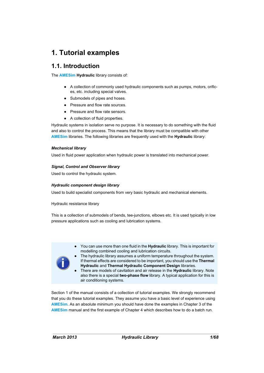
1. Tutorial examples 1.1. Introduction The AMESim Hydraulic library consists of: ● A collection of commonly used hydraulic components such as pumps, motors, orific- es, etc. including special valves. ● Submodels of pipes and hoses. ● Pressure and flow rate sources. ● Pressure and flow rate sensors. ● A collection of fluid properties. Hydraulic systems in isolation serve no purpose. It is necessary to do something with the fluid and also to control the process. This means that the library must be compatible with other AMESim libraries. The following libraries are frequently used with the Hydraulic library: Mechanical library Used in fluid power application when hydraulic power is translated into mechanical power. Signal, Control and Observer library Used to control the hydraulic system. Hydraulic component design library Used to build specialist components from very basic hydraulic and mechanical elements. Hydraulic resistance library This is a collection of submodels of bends, tee-junctions, elbows etc. It is used typically in low pressure applications such as cooling and lubrication systems. ● You can use more than one fluid in the Hydraulic library. This is important for modelling combined cooling and lubrication circuits. ● The hydraulic library assumes a uniform temperature throughout the system. If thermal effects are considered to be important, you should use the Thermal Hydraulic and Thermal Hydraulic Component Design libraries. ● There are models of cavitation and air release in the Hydraulic library. Note also there is a special two-phase flow library. A typical application for this is air conditioning systems. Section 1 of the manual consists of a collection of tutorial examples. We strongly recommend that you do these tutorial examples. They assume you have a basic level of experience using AMESim. As an absolute minimum you should have done the examples in Chapter 3 of the AMESim manual and the first example of Chapter 4 which describes how to do a batch run. March 2013 Hydraulic Library 1/68
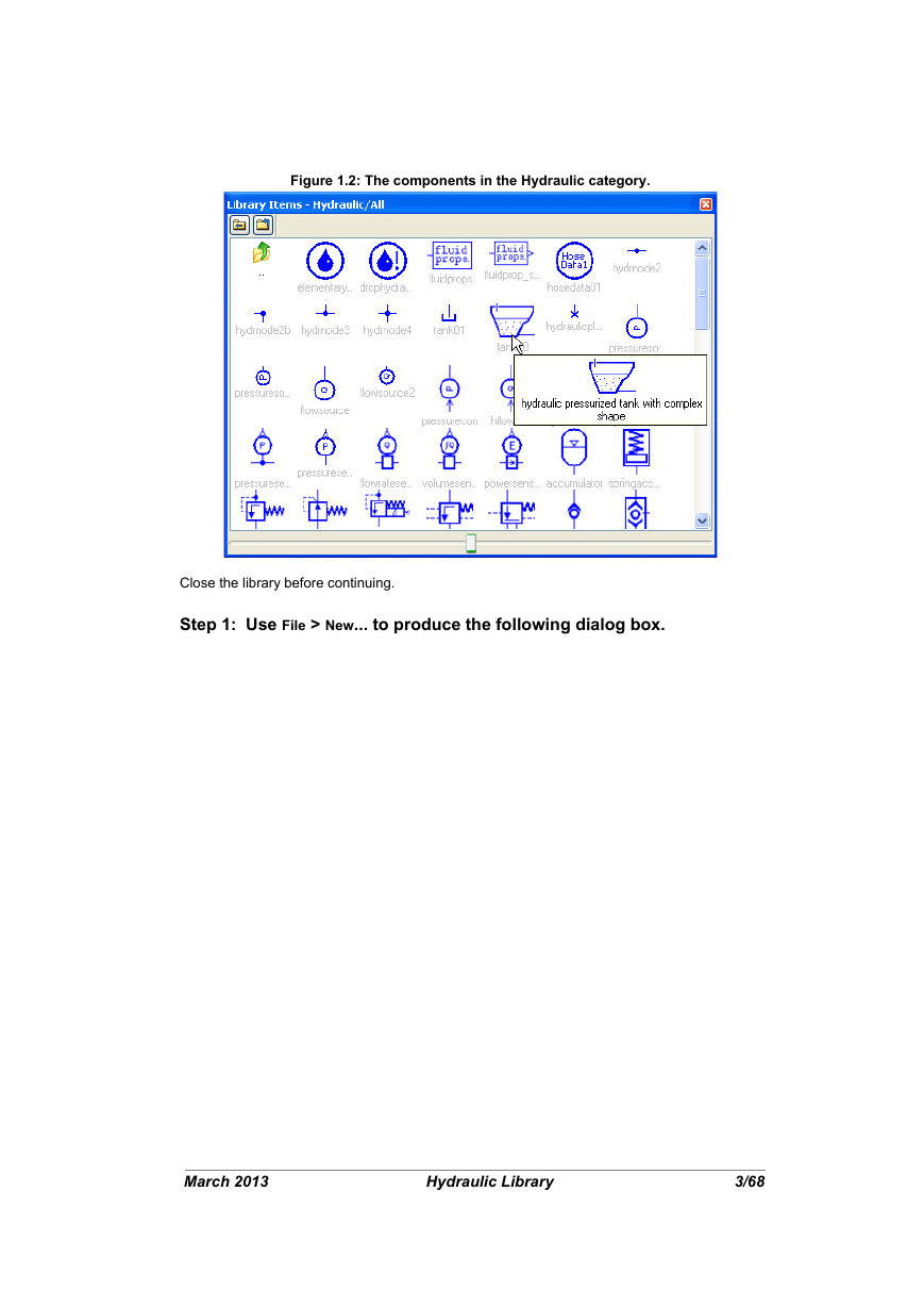
1.2. Example 1: A simple hydraulic system Objectives ● Construct a very simple hydraulic system ● Introduce the simplest pipe/hose submodels ● Interpret the results with a special reference to air release and cavitation Figure 1.1: A very simple hydraulic system In this exercise you will construct the system shown in Figure 1.1. This is perhaps the simplest possible meaningful hydraulic system. It is built partly from components from the Hydraulic category (which are normally blue) and partly from the Mechanical category (in green). The hydraulic section is built from standard symbols used for hydraulic systems. The prime mover supplies power to the pump, which draws hydraulic fluid from a tank. This fluid is supplied under pressure to a hydraulic motor, which drives a rotary load. A relief valve opens when the pressure reaches a certain value. The output from the motor and the relief valve returns to the tank. The diagram shows three tanks but it is quite likely that a single tank is employed. The first category contains general hydraulic components. The second contains special valves.The hydraulic components used in the model you will build can all be found in the first of these Hydraulic categories. If you click on this category icon, the dialog box shown in Figure 1.2 opens. First look at the components available in this library. Display the title of components by moving the pointer over the icons: March 2013 Hydraulic Library 2/68
Figure 1.2: The components in the Hydraulic category. Close the library before continuing. Step 1: Use File > New... to produce the following dialog box. March 2013 Hydraulic Library 3/68
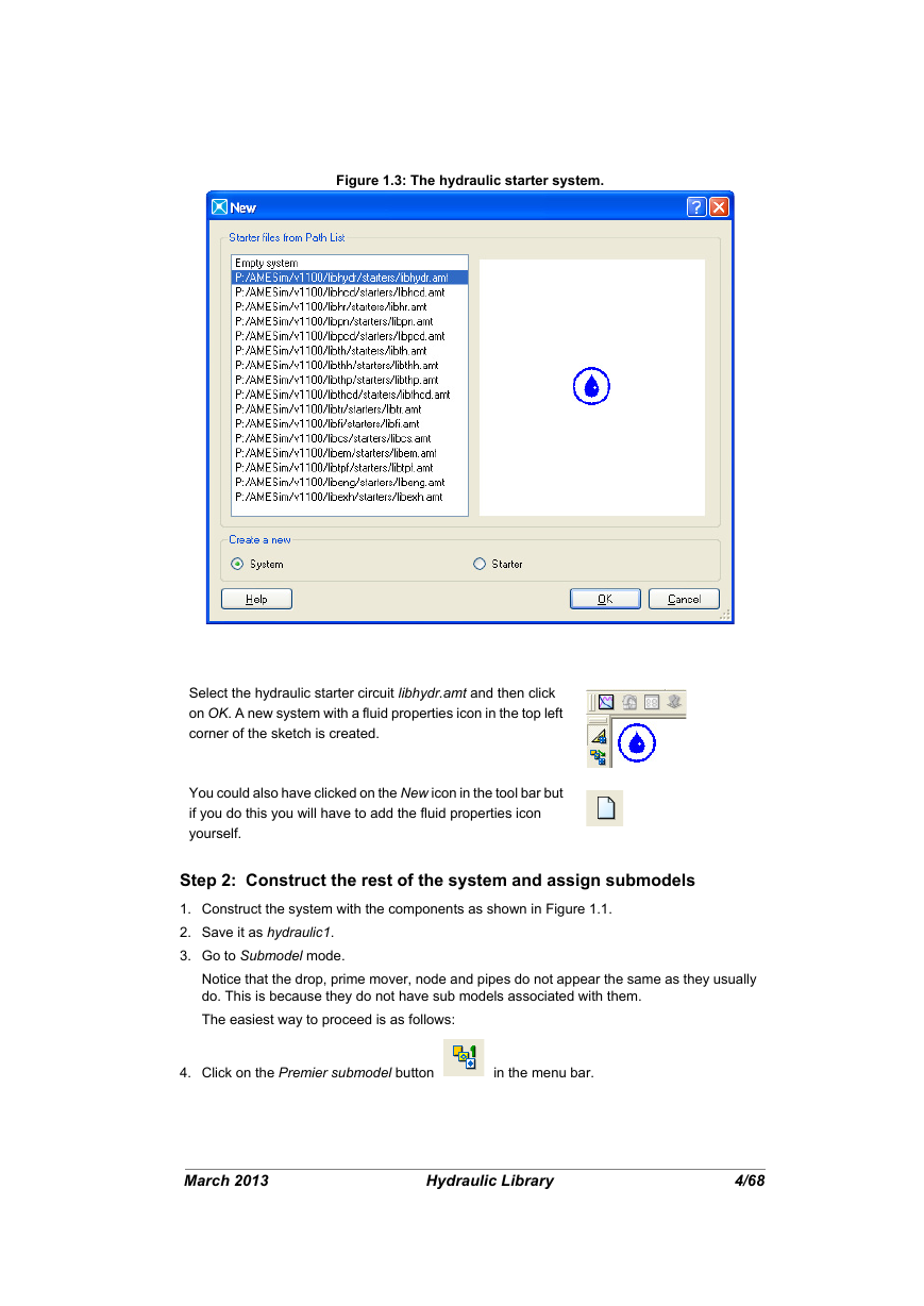
Figure 1.3: The hydraulic starter system. Select the hydraulic starter circuit libhydr.amt and then click on OK. A new system with a fluid properties icon in the top left corner of the sketch is created. You could also have clicked on the New icon in the tool bar but if you do this you will have to add the fluid properties icon yourself. Step 2: Construct the rest of the system and assign submodels 1. Construct the system with the components as shown in Figure 1.1. 2. Save it as hydraulic1. 3. Go to Submodel mode. Notice that the drop, prime mover, node and pipes do not appear the same as they usually do. This is because they do not have sub models associated with them. The easiest way to proceed is as follows: 4. Click on the Premier submodel button in the menu bar. March 2013 Hydraulic Library 4/68
分享到:
收藏