PCI Local Bus
Specification
Revision 2.2
December 18, 1998
�
Revision 2.2
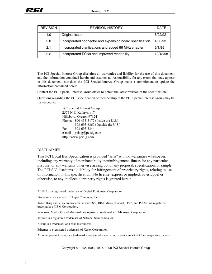
REVISION
REVISION HISTORY
Original issue
DATE
6/22/92
1.0
2.0
2.1
2.2
Incorporated connector and expansion board specification
4/30/93
Incorporated clarifications and added 66 MHz chapter
6/1/95
Incorporated ECNs and improved readability
12/18/98
7KH3&,6SHFLDO,QWHUHVW*URXSGLVFODLPVDOOZDUUDQWLHVDQGOLDELOLW\IRUWKHXVHRIWKLVGRFXPHQW
DQGWKHLQIRUPDWLRQFRQWDLQHGKHUHLQDQGDVVXPHVQRUHVSRQVLELOLW\IRUDQ\HUURUVWKDWPD\DSSHDU
LQ WKLV GRFXPHQW QRU GRHV WKH 3&, 6SHFLDO ,QWHUHVW *URXS PDNH D FRPPLWPHQW WR XSGDWH WKH
LQIRUPDWLRQFRQWDLQHGKHUHLQ
&RQWDFWWKH3&,6SHFLDO,QWHUHVW*URXSRIILFHWRREWDLQWKHODWHVWUHYLVLRQRIWKHVSHFLILFDWLRQ
4XHVWLRQVUHJDUGLQJWKH3&,VSHFLILFDWLRQRUPHPEHUVKLSLQWKH3&,6SHFLDO,QWHUHVW*URXSPD\EH
IRUZDUGHGWR
3&,6SHFLDO,QWHUHVW*URXS
1(.DWKU\Q
+LOOVERUR2UHJRQ
3KRQH ,QVLGHWKH86
2XWVLGHWKH86
SFLVLJ#SFLVLJFRP
)D[
HPDLO
http://www.pcisig.com
’,6&/$,0(5
7KLV3&,/RFDO%XV6SHFLILFDWLRQLVSURYLGHGDVLVZLWKQRZDUUDQWLHVZKDWVRHYHU
LQFOXGLQJDQ\ZDUUDQW\RIPHUFKDQWDELOLW\QRQLQIULQJHPHQWILWQHVVIRUDQ\SDUWLFXODU
SXUSRVHRUDQ\ZDUUDQW\RWKHUZLVHDULVLQJRXWRIDQ\SURSRVDOVSHFLILFDWLRQRUVDPSOH
7KH3&,6,*GLVFODLPVDOOOLDELOLW\IRULQIULQJHPHQWRISURSULHWDU\ULJKWVUHODWLQJWRXVH
RILQIRUPDWLRQLQWKLVVSHFLILFDWLRQ1ROLFHQVHH[SUHVVRULPSOLHGE\HVWRSSHORU
RWKHUZLVHWRDQ\LQWHOOHFWXDOSURSHUW\ULJKWVLVJUDQWHGKHUHLQ
$/3+$LVDUHJLVWHUHGWUDGHPDUNRI’LJLWDO(TXLSPHQW&RUSRUDWLRQ
)LUH:LUHLVDWUDGHPDUNRI$SSOH&RPSXWHU,QF
7RNHQ5LQJDQG9*$DUHWUDGHPDUNVDQG36,%00LFUR&KDQQHO26DQG3&$7DUHUHJLVWHUHG
WUDGHPDUNVRI,%0&RUSRUDWLRQ
:LQGRZV06’26DQG0LFURVRIWDUHUHJLVWHUHGWUDGHPDUNVRI0LFURVRIW&RUSRUDWLRQ
7ULVWDWHLVDUHJLVWHUHGWUDGHPDUNRI1DWLRQDO6HPLFRQGXFWRU
1X%XVLVDWUDGHPDUNRI7H[DV,QVWUXPHQWV
(WKHUQHWLVDUHJLVWHUHGWUDGHPDUNRI;HUR[&RUSRUDWLRQ
$OORWKHUSURGXFWQDPHVDUHWUDGHPDUNVUHJLVWHUHGWUDGHPDUNVRUVHUYLFHPDUNVRIWKHLUUHVSHFWLYHRZQHUV
Copyright © 1992, 1993, 1995, 1998 PCI Special Interest Group
ii
�
Revision 2.2
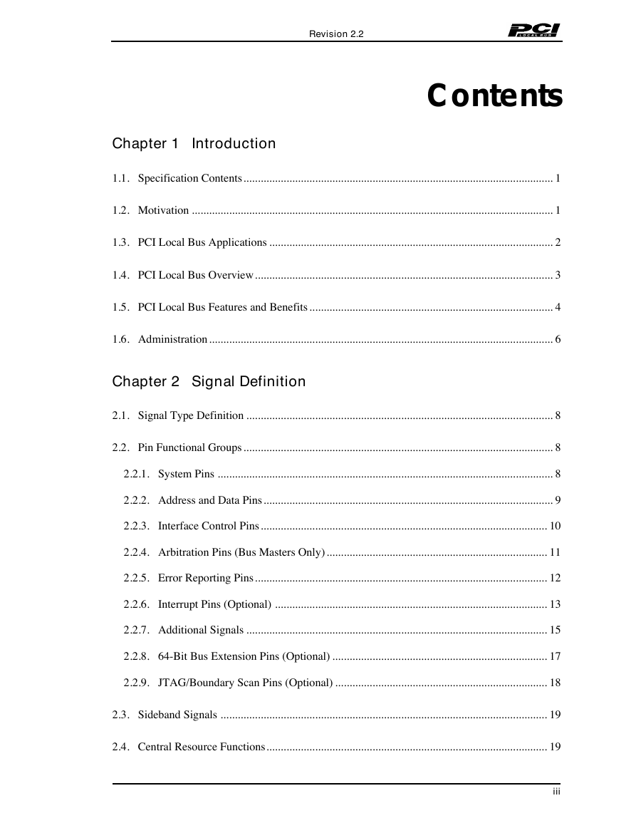
Contents
Chapter 1 Introduction
1.1. Specification Contents............................................................................................................ 1
1.2. Motivation .............................................................................................................................. 1
1.3. PCI Local Bus Applications ................................................................................................... 2
1.4. PCI Local Bus Overview........................................................................................................ 3
1.5. PCI Local Bus Features and Benefits..................................................................................... 4
1.6. Administration........................................................................................................................ 6
Chapter 2 Signal Definition
2.1. Signal Type Definition ........................................................................................................... 8
2.2. Pin Functional Groups............................................................................................................ 8
2.2.1. System Pins ..................................................................................................................... 8
2.2.2. Address and Data Pins..................................................................................................... 9
2.2.3. Interface Control Pins.................................................................................................... 10
2.2.4. Arbitration Pins (Bus Masters Only)............................................................................. 11
2.2.5. Error Reporting Pins...................................................................................................... 12
2.2.6. Interrupt Pins (Optional) ............................................................................................... 13
2.2.7. Additional Signals ......................................................................................................... 15
2.2.8. 64-Bit Bus Extension Pins (Optional) ........................................................................... 17
2.2.9. JTAG/Boundary Scan Pins (Optional) .......................................................................... 18
2.3. Sideband Signals .................................................................................................................. 19
2.4. Central Resource Functions.................................................................................................. 19
iii
�
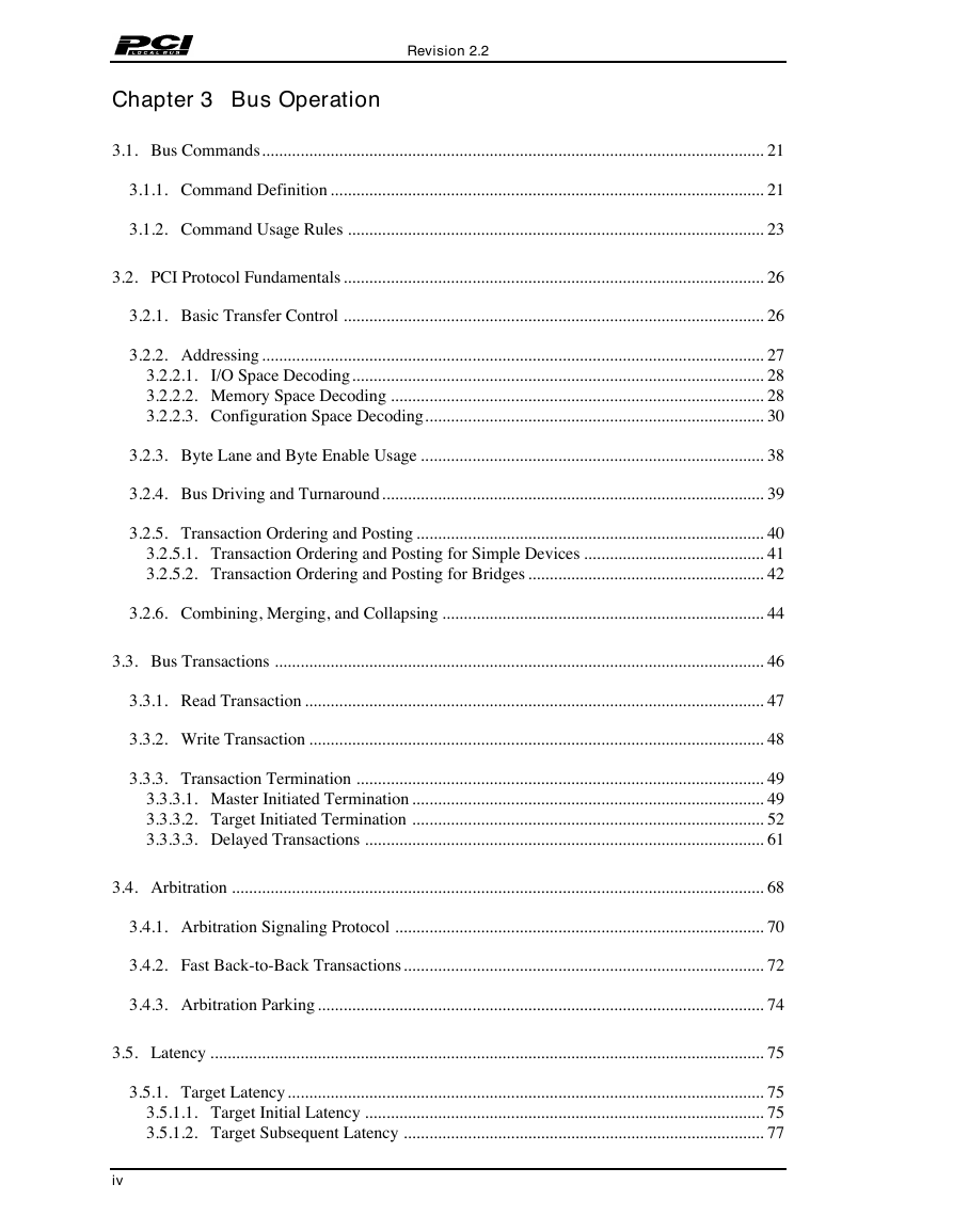
Chapter 3 Bus Operation
Revision 2.2
3.1. Bus Commands..................................................................................................................... 21
3.1.1. Command Definition ..................................................................................................... 21
3.1.2. Command Usage Rules ................................................................................................. 23
3.2. PCI Protocol Fundamentals .................................................................................................. 26
3.2.1. Basic Transfer Control .................................................................................................. 26
3.2.2. Addressing ..................................................................................................................... 27
3.2.2.1. I/O Space Decoding................................................................................................ 28
3.2.2.2. Memory Space Decoding ....................................................................................... 28
3.2.2.3. Configuration Space Decoding............................................................................... 30
3.2.3. Byte Lane and Byte Enable Usage ................................................................................ 38
3.2.4. Bus Driving and Turnaround......................................................................................... 39
3.2.5. Transaction Ordering and Posting ................................................................................. 40
3.2.5.1. Transaction Ordering and Posting for Simple Devices .......................................... 41
3.2.5.2. Transaction Ordering and Posting for Bridges ....................................................... 42
3.2.6. Combining, Merging, and Collapsing ........................................................................... 44
3.3. Bus Transactions .................................................................................................................. 46
3.3.1. Read Transaction ........................................................................................................... 47
3.3.2. Write Transaction .......................................................................................................... 48
3.3.3. Transaction Termination ............................................................................................... 49
3.3.3.1. Master Initiated Termination .................................................................................. 49
3.3.3.2. Target Initiated Termination .................................................................................. 52
3.3.3.3. Delayed Transactions ............................................................................................. 61
3.4. Arbitration ............................................................................................................................ 68
3.4.1. Arbitration Signaling Protocol ...................................................................................... 70
3.4.2. Fast Back-to-Back Transactions.................................................................................... 72
3.4.3. Arbitration Parking ........................................................................................................ 74
3.5. Latency ................................................................................................................................. 75
3.5.1. Target Latency............................................................................................................... 75
3.5.1.1. Target Initial Latency ............................................................................................. 75
3.5.1.2. Target Subsequent Latency .................................................................................... 77
iv
�
Revision 2.2
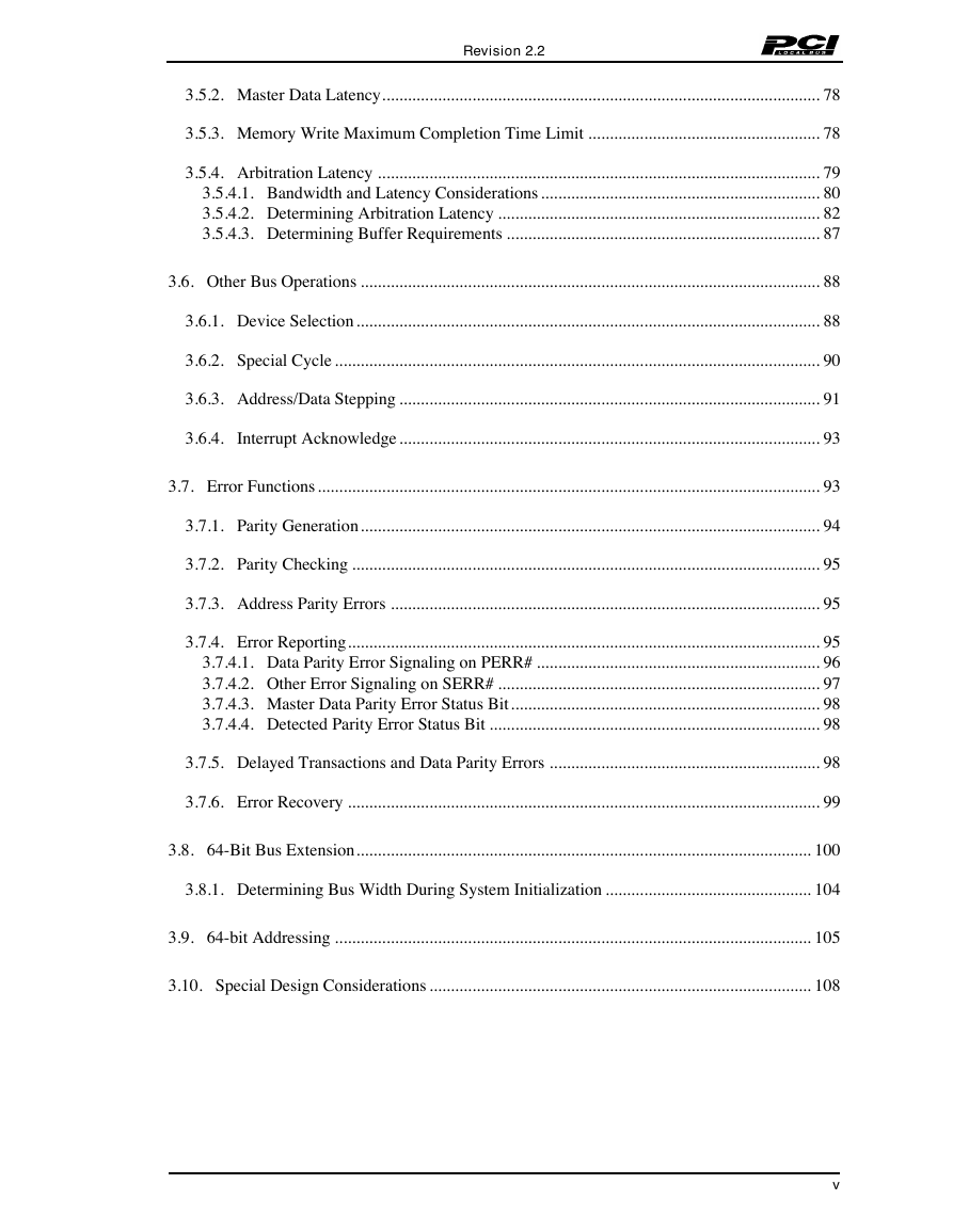
3.5.2. Master Data Latency...................................................................................................... 78
3.5.3. Memory Write Maximum Completion Time Limit ...................................................... 78
3.5.4. Arbitration Latency ....................................................................................................... 79
3.5.4.1. Bandwidth and Latency Considerations ................................................................. 80
3.5.4.2. Determining Arbitration Latency ........................................................................... 82
3.5.4.3. Determining Buffer Requirements ......................................................................... 87
3.6. Other Bus Operations ........................................................................................................... 88
3.6.1. Device Selection............................................................................................................ 88
3.6.2. Special Cycle ................................................................................................................. 90
3.6.3. Address/Data Stepping .................................................................................................. 91
3.6.4. Interrupt Acknowledge.................................................................................................. 93
3.7. Error Functions..................................................................................................................... 93
3.7.1. Parity Generation........................................................................................................... 94
3.7.2. Parity Checking ............................................................................................................. 95
3.7.3. Address Parity Errors .................................................................................................... 95
3.7.4. Error Reporting.............................................................................................................. 95
3.7.4.1. Data Parity Error Signaling on PERR# .................................................................. 96
3.7.4.2. Other Error Signaling on SERR# ........................................................................... 97
3.7.4.3. Master Data Parity Error Status Bit........................................................................ 98
3.7.4.4. Detected Parity Error Status Bit ............................................................................. 98
3.7.5. Delayed Transactions and Data Parity Errors ............................................................... 98
3.7.6. Error Recovery .............................................................................................................. 99
3.8. 64-Bit Bus Extension.......................................................................................................... 100
3.8.1. Determining Bus Width During System Initialization ................................................ 104
3.9. 64-bit Addressing ............................................................................................................... 105
3.10. Special Design Considerations ......................................................................................... 108
v
�
Revision 2.2
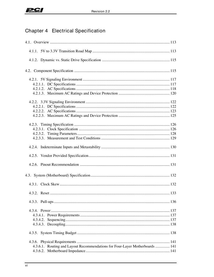
Chapter 4 Electrical Specification
4.1. Overview ............................................................................................................................ 113
4.1.1. 5V to 3.3V Transition Road Map ................................................................................ 113
4.1.2. Dynamic vs. Static Drive Specification ...................................................................... 115
4.2. Component Specification ................................................................................................... 115
4.2.1. 5V Signaling Environment .......................................................................................... 117
4.2.1.1. DC Specifications ................................................................................................. 117
4.2.1.2. AC Specifications ................................................................................................. 118
4.2.1.3. Maximum AC Ratings and Device Protection ..................................................... 120
4.2.2. 3.3V Signaling Environment ....................................................................................... 122
4.2.2.1. DC Specifications ................................................................................................. 122
4.2.2.2. AC Specifications ................................................................................................. 123
4.2.2.3. Maximum AC Ratings and Device Protection ..................................................... 125
4.2.3. Timing Specification ................................................................................................... 126
4.2.3.1. Clock Specification .............................................................................................. 126
4.2.3.2. Timing Parameters................................................................................................ 128
4.2.3.3. Measurement and Test Conditions ....................................................................... 129
4.2.4. Indeterminate Inputs and Metastability ....................................................................... 130
4.2.5. Vendor Provided Specification.................................................................................... 131
4.2.6. Pinout Recommendation ............................................................................................. 131
4.3. System (Motherboard) Specification.................................................................................. 132
4.3.1. Clock Skew.................................................................................................................. 132
4.3.2. Reset ............................................................................................................................ 133
4.3.3. Pull-ups........................................................................................................................ 136
4.3.4. Power ........................................................................................................................... 137
4.3.4.1. Power Requirements............................................................................................. 137
4.3.4.2. Sequencing............................................................................................................ 137
4.3.4.3. Decoupling............................................................................................................ 138
4.3.5. System Timing Budget ................................................................................................ 138
4.3.6. Physical Requirements ................................................................................................ 141
4.3.6.1. Routing and Layout Recommendations for Four-Layer Motherboards ............... 141
4.3.6.2. Motherboard Impedance....................................................................................... 141
vi
�
Revision 2.2
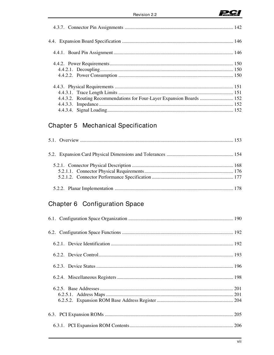
4.3.7. Connector Pin Assignments ........................................................................................ 142
4.4. Expansion Board Specification .......................................................................................... 146
4.4.1. Board Pin Assignment................................................................................................. 146
4.4.2. Power Requirements.................................................................................................... 150
4.4.2.1. Decoupling............................................................................................................ 150
4.4.2.2. Power Consumption ............................................................................................. 150
4.4.3. Physical Requirements ................................................................................................ 151
4.4.3.1. Trace Length Limits ............................................................................................. 151
4.4.3.2. Routing Recommendations for Four-Layer Expansion Boards ........................... 152
4.4.3.3. Impedance............................................................................................................. 152
4.4.3.4. Signal Loading...................................................................................................... 152
Chapter 5 Mechanical Specification
5.1. Overview ............................................................................................................................ 153
5.2. Expansion Card Physical Dimensions and Tolerances ...................................................... 154
5.2.1. Connector Physical Description .................................................................................. 168
5.2.1.1. Connector Physical Requirements........................................................................ 176
5.2.1.2. Connector Performance Specification .................................................................. 177
5.2.2. Planar Implementation ................................................................................................ 178
Chapter 6 Configuration Space
6.1. Configuration Space Organization ..................................................................................... 190
6.2. Configuration Space Functions .......................................................................................... 192
6.2.1. Device Identification ................................................................................................... 192
6.2.2. Device Control............................................................................................................. 193
6.2.3. Device Status ............................................................................................................... 196
6.2.4. Miscellaneous Registers .............................................................................................. 198
6.2.5. Base Addresses............................................................................................................ 201
6.2.5.1. Address Maps ....................................................................................................... 201
6.2.5.2. Expansion ROM Base Address Register .............................................................. 204
6.3. PCI Expansion ROMs ........................................................................................................ 205
6.3.1. PCI Expansion ROM Contents.................................................................................... 206
vii
�
Revision 2.2
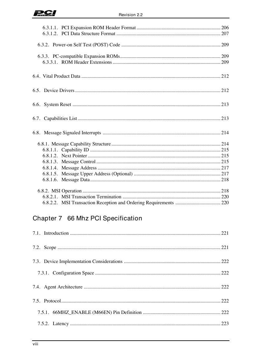
6.3.1.1. PCI Expansion ROM Header Format................................................................... 206
6.3.1.2. PCI Data Structure Format ................................................................................... 207
6.3.2. Power-on Self Test (POST) Code ............................................................................... 209
6.3.3. PC-compatible Expansion ROMs................................................................................ 209
6.3.3.1. ROM Header Extensions ...................................................................................... 209
6.4. Vital Product Data ............................................................................................................... 212
6.5. Device Drivers.................................................................................................................... 212
6.6. System Reset ...................................................................................................................... 213
6.7. Capabilities List.................................................................................................................. 213
6.8. Message Signaled Interrupts .............................................................................................. 214
6.8.1. Message Capability Structure....................................................................................... 214
6.8.1.1. Capability ID ........................................................................................................ 215
6.8.1.2. Next Pointer.......................................................................................................... 215
6.8.1.3. Message Control ................................................................................................... 215
6.8.1.4. Message Address .................................................................................................. 217
6.8.1.5. Message Upper Address (Optional) ..................................................................... 217
6.8.1.6. Message Data........................................................................................................ 218
6.8.2. MSI Operation .............................................................................................................. 218
6.8.2.1. MSI Transaction Termination .............................................................................. 220
6.8.2.2. MSI Transaction Reception and Ordering Requirements .................................... 220
Chapter 7 66 Mhz PCI Specification
7.1. Introduction ........................................................................................................................ 221
7.2. Scope .................................................................................................................................. 221
7.3. Device Implementation Considerations ............................................................................. 222
7.3.1. Configuration Space .................................................................................................... 222
7.4. Agent Architecture ............................................................................................................. 222
7.5. Protocol............................................................................................................................... 222
7.5.1. 66MHZ_ENABLE (M66EN) Pin Definition .............................................................. 222
7.5.2. Latency ........................................................................................................................ 223
viii
�


 2023年江西萍乡中考道德与法治真题及答案.doc
 2012年重庆南川中考生物真题及答案.doc
 2013年江西师范大学地理学综合及文艺理论基础考研真题.doc
 2020年四川甘孜小升初语文真题及答案I卷.doc
 2020年注册岩土工程师专业基础考试真题及答案.doc
 2023-2024学年福建省厦门市九年级上学期数学月考试题及答案.doc
 2021-2022学年辽宁省沈阳市大东区九年级上学期语文期末试题及答案.doc
 2022-2023学年北京东城区初三第一学期物理期末试卷及答案.doc
 2018上半年江西教师资格初中地理学科知识与教学能力真题及答案.doc
 2012年河北国家公务员申论考试真题及答案-省级.doc
 2020-2021学年江苏省扬州市江都区邵樊片九年级上学期数学第一次质量检测试题及答案.doc
 2022下半年黑龙江教师资格证中学综合素质真题及答案.doc