logo资料库

SigFit帮助文档v2019r1b.pdf

第1页 / 共178页
第2页 / 共178页
第3页 / 共178页
第4页 / 共178页
第5页 / 共178页
第6页 / 共178页
第7页 / 共178页
第8页 / 共178页
资料共178页,剩余部分请下载后查看
1 Surface Fitting Example
1.1 Tutorial Format
1.2 Features Demonstrated
1.3 Example Model Description
1.4 Load Cases
1.5 Finite Element Model Files
1.5.1 NASTRAN Model and Punch File
1.5.2 ANSYS Mechanical APDL Model and .asig File
1.5.3 ANSYS Workbench Model and .asig File
1.5.4 ABAQUS Model and .odb File
1.5.5 SolidWorks Model
1.6 SigFit Input Files (.sig)
1.7 SigFit Output File (.fit)
1.8 Contour Plots from Nodal File
1.8.1 Making Plots in MSC.Patran
1.8.2 Making Plots in ANSYS Mechanical APDL
1.8.3 Making Plots in ABAQUS CAE
1.8.4 Contour Plotting Observations
1.9 SigFit Polynomial Coefficient Output File
1.10 Optical Analysis Files
1.10.1 Optical Analysis Model
1.10.2 CODEV .seq Macro File
1.10.3 ZEMAX .zpl Macro File
1.10.4 OSLO .scp Macro File
1.10.5 Zernike INT (.int) Output File
1.11 Performing the Optical Analysis
1.11.1 Applying the Disturbances in CODEV
1.11.2 Applying the Disturbances in ZEMAX
2 Active Control Example
2.1 Tutorial Format
2.2 Features Illustrated
2.3 Model Description
2.4 Load Cases
2.5 FE Model File
2.5.1 NASTRAN Model and Punch File
2.5.2 ANSYS Mechanical APDL Model and .asig File
2.5.3 ABAQUS Model and .odb File
2.6 SigFit Input Files (.sig)
2.7 SigFit Active Control Output File (.fit)
2.8 Contour Plots from Nodal File
2.9 SigFit Air Bag Analysis Output File
3 Random Response Example
3.1 Features Displayed
3.2 Model Description
3.3 Load Condition
3.4 Two Methods of Dynamic Analysis in SigFit
3.5 FE Model File
3.5.1 NASTRAN Model and Punch File
3.5.2 ANSYS Mechanical APDL Model and .asig File
3.5.3 ANSYS Workbench Model and .asig File
3.5.4 ABAQUS Model and .odb File
3.6 SigFit Input File
3.7 SigFit Output File
3.8 SigFit Comparison to Random Response in MSC.Nastran
3.9 Discussion
4 Interpolation Example - Interferogram I/O
4.1 Features Displayed
4.2 Model Description
4.3 Load Condition
4.4 FE Model File
4.4.1 NASTRAN Model and Punch File
4.4.2 ANSYS Mechanical APDL Model and .asig File
4.5 SigFit Input File
4.5.1 Interferogram Output Files
4.5.2 Interferogram Input Files
4.6 Array File Formats
4.6.1 Rectangular Array Interpolation in GRD INT Format
4.6.2 Rectangular Array Interpolation in ZEMAX Format
4.7 Optional files for visualization
5 Interpolation Example - Cookie (Sub-aperture)
5.1 Features Displayed
5.2 Model Description
5.3 Load Condition
5.4 FE Model Files
5.4.1 NASTRAN Model and Punch File
5.4.2 ANSYS Mechanical APDL Model and .asig File
5.5 SigFit Interpolation Run to Output Displacements on a Cookie
5.6 Zernike Fitting on Cookie
5.7 Applications
6 Equation Generation: Zernike MPC Example
6.1 Features Displayed
6.2 Model Description
6.3 NASTRAN FE Model File
6.4 SigFit Input File
6.5 SigFit Output Files
6.6 Using the Equation File
6.7 Results Comparison
7 Equation Generation: Optimization Example
7.1 Features Displayed
7.2 Model Description
7.3 NASTRAN FE Model File
7.4 SigFit Input File
7.5 SigFit Output Files
7.6 MSC/NASTRAN Input File
7.7 Results Comparison
8 System Analysis: LoS,Telescope
8.1 Tutorial Format
8.2 Features Demonstrated
8.3 Model Descriptions
8.3.1 FE Model for NASTRAN and ANSYS Mechanical APDL
8.3.2 FE Model for ANSYS Workbench
8.4 Load Cases
8.5 Finite Element Model Files
8.5.1 NASTRAN Model and Punch File
8.5.2 ANSYS Mechanical APDL Model and .asig File
8.5.3 ANSYS Workbench Model and .asig File
8.6 SigFit Input Files (.sig)
8.6.1 Analysis of Static Deformations
8.6.2 Analysis of Random Response Deformation
8.6.3 Generation of State Space Matrices
8.6.4 Generation of Surface RMS and LoS Error Equations
8.7 Performing the Optical Analysis
9 Refractive Effects Example
9.1 Tutorial Format
9.2 Features Demonstrated
9.3 Model Description
9.4 Load Cases
9.5 Finite Element Model Files
9.5.1 NASTRAN Model and Punch File
9.5.2 ANSYS Mechanical APDL Model and .asig File
9.5.3 ANSYS Workbench Model and .asig File
9.5.4 Abaqus Model and ODB File
9.5.5 SolidWorks Simulation Model File
9.6 Optical Analysis Files
9.6.1 CODEV Optical Analysis Model
9.6.2 ZEMAX Optical Analysis Models
9.7 SigFit Input Files (.sig)
9.7.1 Thermo-Optic Analysis
9.7.2 Stress-Optic and Stress-Induced Birefringence Analysis
9.8 SigFit Output Files
9.8.1 Thermo-Optic Analysis
9.8.2 Stress-Induced Birefringence Analysis
10 Polynomial Conversion Example
10.1 Features Displayed
10.2 Model Description
10.3 Polynomial conversion
10.4 SigFit input file
10.5 SigFit output file (note: 1 wave = 1 micron)
11 Off-Axis Asphere Polynomial Example
11.1 Features Displayed
11.2 Model Description
11.3 SigFit input file
11.4 SigFit output file
12 Aero-Optic Analysis
12.1 Features Displayed
12.2 Model Description
12.3 Finite Element Model Files
12.4 SigFit Input Files (.sig)
12.4.1 Solution Module Settings
12.4.2 Geometry Module Settings
12.4.3 Defining Material Properties
12.5 SigFit Output Files
13 Diffractive Optics
13.1 Features Displayed
13.2 Model Description
13.3 Finite Element Model Files
13.3.1 NASTRAN Model and Punch File
13.3.2 ANSYS Mechanical APDL Model and .asig File
13.3.3 ABAQUS Model and .odb File
13.4 SigFit Input and Corresponding Nominal Optical Model Files
13.4.1 Settings in SigFit for Linear Gratings
13.4.2 Settings in SigFit for Phase Surfaces
13.4.3 Settings in SigFit for Polynomial Fitting of Diffractive Phase
13.5 SigFit Output Files for Diffractive Optic Analysis
14 Segmented Mirror Example
14.1 Features Displayed
14.2 Model Description
14.3 Load Condition
14.4 FE Model File
14.4.1 NASTRAN Model and Punch File
14.5 Surface Deformation Analysis with Segments
14.5.1 Analysis Definition for Surface Deformation Analysis with Segments
14.5.2 Output for Surface Deformation Analysis with Segments
14.6 Racking Analysis with Segments
14.6.1 Analysis Definition of Racking Analysis
14.7 Line-of-Sight Error in Random Response Analysis with Segments
14.7.1 Analysis Definition for Line-of-Sight Error Analysis With Segments
14.7.2 Output of Line-of-Sight Error Analysis with Segments
___________________________________________________________________________________________________ SigFit Examples Manual Version 2019R1b ___________________________________________________________________________________________________ July 23, 2019 Sigmadyne, Inc. 803 West Avenue Rochester, NY 14611 www.sigmadyne.com
Warning: Use of this program is subject to the terms of the Demo Software Agreement or the Software Agreement agreed upon in writing with the User's authorized representative(s). Installation of this software indicates acceptance of the Software Agreement. Technical Support IMPORTANT: When contacting technical support please provide the following: 1. Your .sig file defining your SigFit analysis. 2. All files referenced by the .sig file. This includes FEA model files, FEA results files, OLOAD files, VECTOR files, etc. 3. The nature of the problem and the error you are seeing, if any. Licensing Issues Gregory Michels (585) 235-6892 michels@sigmadyne.com Visual SigFit Gregory Michels (585) 235-6892 michels@sigmadyne.com SigFit Engine Victor Genberg (585) 235-7460 genberg@sigmadyne.com Gregory Michels (585) 235-6892 michels@sigmadyne.com For more information about Sigmadyne visit our website at: www.sigmadyne.com. The background theory used in SigFit is discussed in the following book & short courses: Doyle, K., Genberg, V., Michels, G., Integrated Optomechanical Analysis, Second Edition, SPIE Press, November, 2012. Integrated Optomechanical Analysis short course available from Sigmadyne, Inc. SigFit short course available from Sigmadyne, Inc. Copyright © 2019 Sigmadyne, Inc. All rights reserved. No part of this publication may be reproduced or distributed in any form or by any means without written permission from Sigmadyne, Inc. i
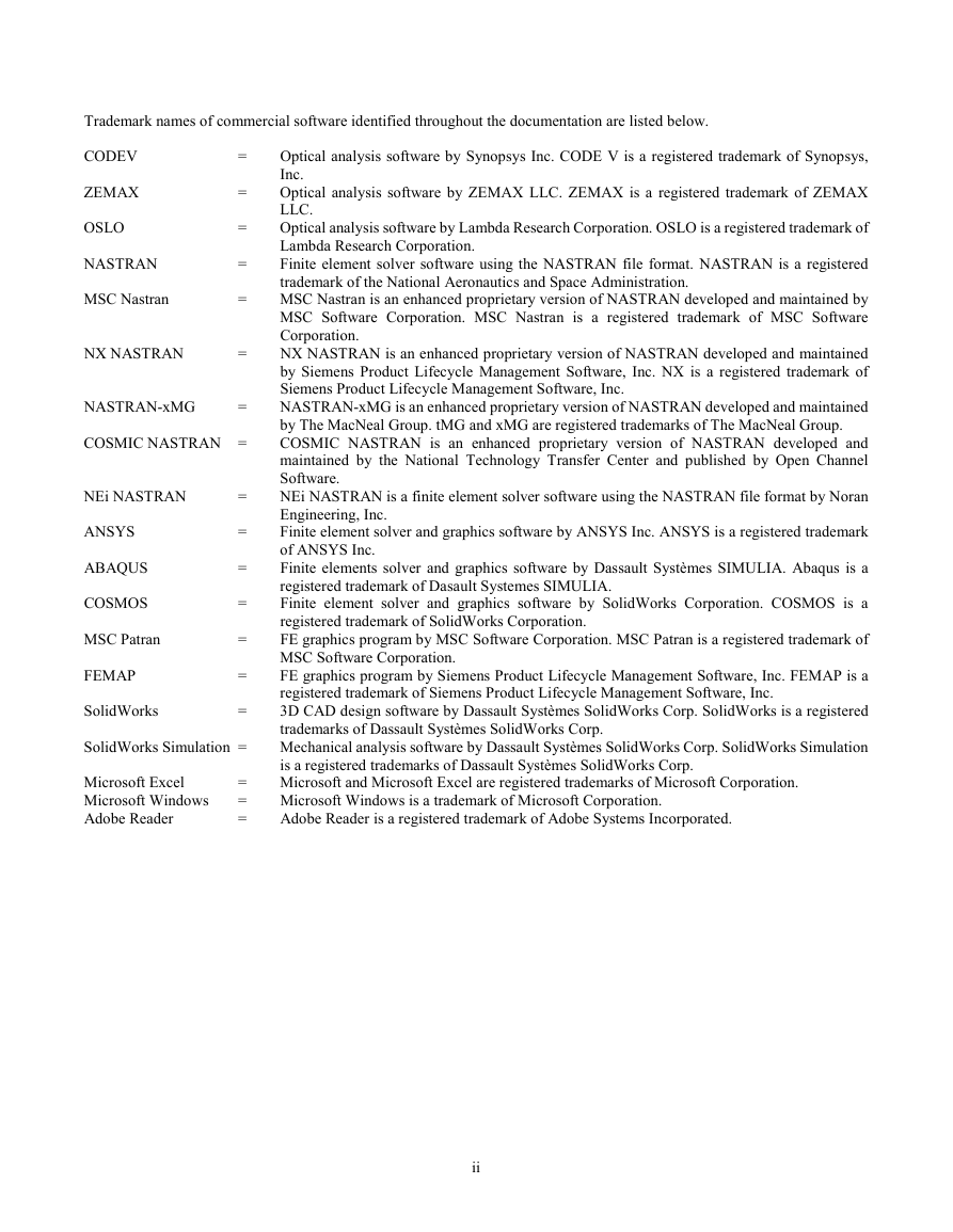
ZEMAX OSLO NASTRAN MSC Nastran NX NASTRAN NASTRAN-xMG = = = = = = COSMIC NASTRAN = NEi NASTRAN ANSYS ABAQUS COSMOS MSC Patran FEMAP SolidWorks = = = = = = = SolidWorks Simulation = Microsoft Excel Microsoft Windows Adobe Reader = = = Trademark names of commercial software identified throughout the documentation are listed below. CODEV = Optical analysis software by Synopsys Inc. CODE V is a registered trademark of Synopsys, Inc. Optical analysis software by ZEMAX LLC. ZEMAX is a registered trademark of ZEMAX LLC. Optical analysis software by Lambda Research Corporation. OSLO is a registered trademark of Lambda Research Corporation. Finite element solver software using the NASTRAN file format. NASTRAN is a registered trademark of the National Aeronautics and Space Administration. MSC Nastran is an enhanced proprietary version of NASTRAN developed and maintained by MSC Software Corporation. MSC Nastran is a registered trademark of MSC Software Corporation. NX NASTRAN is an enhanced proprietary version of NASTRAN developed and maintained by Siemens Product Lifecycle Management Software, Inc. NX is a registered trademark of Siemens Product Lifecycle Management Software, Inc. NASTRAN-xMG is an enhanced proprietary version of NASTRAN developed and maintained by The MacNeal Group. tMG and xMG are registered trademarks of The MacNeal Group. COSMIC NASTRAN is an enhanced proprietary version of NASTRAN developed and maintained by the National Technology Transfer Center and published by Open Channel Software. NEi NASTRAN is a finite element solver software using the NASTRAN file format by Noran Engineering, Inc. Finite element solver and graphics software by ANSYS Inc. ANSYS is a registered trademark of ANSYS Inc. Finite elements solver and graphics software by Dassault Systèmes SIMULIA. Abaqus is a registered trademark of Dasault Systemes SIMULIA. Finite element solver and graphics software by SolidWorks Corporation. COSMOS is a registered trademark of SolidWorks Corporation. FE graphics program by MSC Software Corporation. MSC Patran is a registered trademark of MSC Software Corporation. FE graphics program by Siemens Product Lifecycle Management Software, Inc. FEMAP is a registered trademark of Siemens Product Lifecycle Management Software, Inc. 3D CAD design software by Dassault Systèmes SolidWorks Corp. SolidWorks is a registered trademarks of Dassault Systèmes SolidWorks Corp. Mechanical analysis software by Dassault Systèmes SolidWorks Corp. SolidWorks Simulation is a registered trademarks of Dassault Systèmes SolidWorks Corp. Microsoft and Microsoft Excel are registered trademarks of Microsoft Corporation. Microsoft Windows is a trademark of Microsoft Corporation. Adobe Reader is a registered trademark of Adobe Systems Incorporated. ii
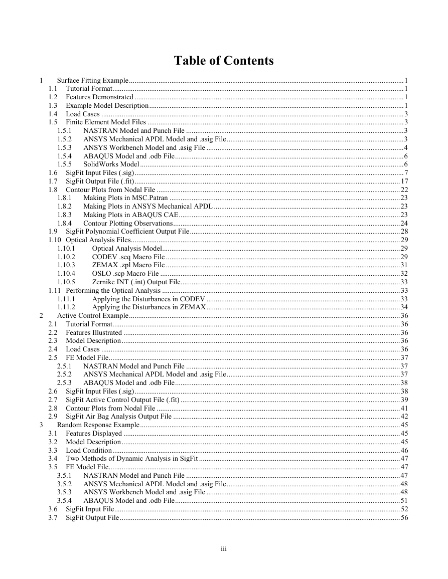
1 2 3 Table of Contents 1.10.1 1.10.2 1.10.3 1.10.4 1.10.5 Surface Fitting Example ..................................................................................................................................................... 1 1.1 Tutorial Format .............................................................................................................................................................. 1 1.2 Features Demonstrated .................................................................................................................................................. 1 1.3 Example Model Description .......................................................................................................................................... 1 1.4 Load Cases .................................................................................................................................................................... 3 1.5 Finite Element Model Files ........................................................................................................................................... 3 1.5.1 NASTRAN Model and Punch File ...................................................................................................................... 3 1.5.2 ANSYS Mechanical APDL Model and .asig File ................................................................................................ 3 1.5.3 ANSYS Workbench Model and .asig File ........................................................................................................... 4 1.5.4 ABAQUS Model and .odb File ............................................................................................................................ 6 1.5.5 SolidWorks Model ............................................................................................................................................... 6 1.6 SigFit Input Files (.sig) .................................................................................................................................................. 7 1.7 SigFit Output File (.fit) ................................................................................................................................................ 17 1.8 Contour Plots from Nodal File .................................................................................................................................... 22 1.8.1 Making Plots in MSC.Patran ............................................................................................................................. 23 1.8.2 Making Plots in ANSYS Mechanical APDL ..................................................................................................... 23 1.8.3 Making Plots in ABAQUS CAE ........................................................................................................................ 23 1.8.4 Contour Plotting Observations ........................................................................................................................... 24 1.9 SigFit Polynomial Coefficient Output File .................................................................................................................. 28 1.10 Optical Analysis Files.................................................................................................................................................. 29 Optical Analysis Model ................................................................................................................................. 29 CODEV .seq Macro File ............................................................................................................................... 29 ZEMAX .zpl Macro File ............................................................................................................................... 31 OSLO .scp Macro File .................................................................................................................................. 32 Zernike INT (.int) Output File ....................................................................................................................... 33 1.11 Performing the Optical Analysis ................................................................................................................................. 33 Applying the Disturbances in CODEV ......................................................................................................... 33 1.11.1 1.11.2 Applying the Disturbances in ZEMAX ......................................................................................................... 34 Active Control Example ................................................................................................................................................... 36 2.1 Tutorial Format ............................................................................................................................................................ 36 2.2 Features Illustrated ...................................................................................................................................................... 36 2.3 Model Description ....................................................................................................................................................... 36 2.4 Load Cases .................................................................................................................................................................. 36 2.5 FE Model File .............................................................................................................................................................. 37 2.5.1 NASTRAN Model and Punch File .................................................................................................................... 37 2.5.2 ANSYS Mechanical APDL Model and .asig File .............................................................................................. 37 2.5.3 ABAQUS Model and .odb File .......................................................................................................................... 38 2.6 SigFit Input Files (.sig) ................................................................................................................................................ 38 2.7 SigFit Active Control Output File (.fit) ....................................................................................................................... 39 2.8 Contour Plots from Nodal File .................................................................................................................................... 41 2.9 SigFit Air Bag Analysis Output File ........................................................................................................................... 42 Random Response Example ............................................................................................................................................. 45 3.1 Features Displayed ...................................................................................................................................................... 45 3.2 Model Description ....................................................................................................................................................... 45 3.3 Load Condition ............................................................................................................................................................ 46 3.4 Two Methods of Dynamic Analysis in SigFit ............................................................................................................. 47 3.5 FE Model File .............................................................................................................................................................. 47 3.5.1 NASTRAN Model and Punch File .................................................................................................................... 47 3.5.2 ANSYS Mechanical APDL Model and .asig File .............................................................................................. 48 3.5.3 ANSYS Workbench Model and .asig File ......................................................................................................... 48 3.5.4 ABAQUS Model and .odb File .......................................................................................................................... 51 3.6 SigFit Input File ........................................................................................................................................................... 52 3.7 SigFit Output File ........................................................................................................................................................ 56 iii
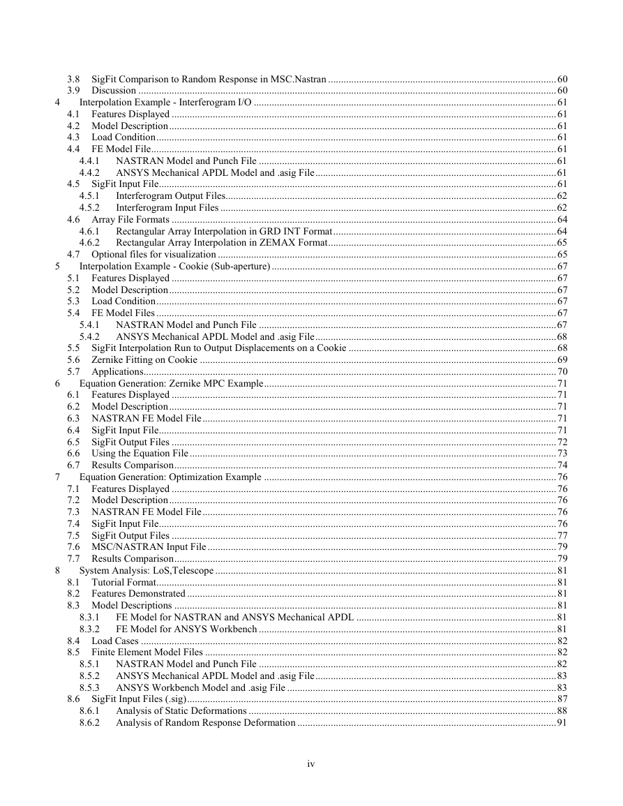
4 5 6 7 8 4.5.1 4.5.2 3.8 SigFit Comparison to Random Response in MSC.Nastran ......................................................................................... 60 3.9 Discussion ................................................................................................................................................................... 60 Interpolation Example - Interferogram I/O ...................................................................................................................... 61 4.1 Features Displayed ...................................................................................................................................................... 61 4.2 Model Description ....................................................................................................................................................... 61 4.3 Load Condition ............................................................................................................................................................ 61 4.4 FE Model File .............................................................................................................................................................. 61 4.4.1 NASTRAN Model and Punch File .................................................................................................................... 61 4.4.2 ANSYS Mechanical APDL Model and .asig File .............................................................................................. 61 4.5 SigFit Input File ........................................................................................................................................................... 61 Interferogram Output Files................................................................................................................................. 62 Interferogram Input Files ................................................................................................................................... 62 4.6 Array File Formats ...................................................................................................................................................... 64 Rectangular Array Interpolation in GRD INT Format ....................................................................................... 64 Rectangular Array Interpolation in ZEMAX Format ......................................................................................... 65 4.7 Optional files for visualization .................................................................................................................................... 65 Interpolation Example - Cookie (Sub-aperture) ............................................................................................................... 67 5.1 Features Displayed ...................................................................................................................................................... 67 5.2 Model Description ....................................................................................................................................................... 67 5.3 Load Condition ............................................................................................................................................................ 67 5.4 FE Model Files ............................................................................................................................................................ 67 5.4.1 NASTRAN Model and Punch File .................................................................................................................... 67 5.4.2 ANSYS Mechanical APDL Model and .asig File .............................................................................................. 68 5.5 SigFit Interpolation Run to Output Displacements on a Cookie ................................................................................. 68 5.6 Zernike Fitting on Cookie ........................................................................................................................................... 69 5.7 Applications................................................................................................................................................................. 70 Equation Generation: Zernike MPC Example .................................................................................................................. 71 6.1 Features Displayed ...................................................................................................................................................... 71 6.2 Model Description ....................................................................................................................................................... 71 6.3 NASTRAN FE Model File .......................................................................................................................................... 71 6.4 SigFit Input File ........................................................................................................................................................... 71 6.5 SigFit Output Files ...................................................................................................................................................... 72 6.6 Using the Equation File ............................................................................................................................................... 73 6.7 Results Comparison ..................................................................................................................................................... 74 Equation Generation: Optimization Example .................................................................................................................. 76 7.1 Features Displayed ...................................................................................................................................................... 76 7.2 Model Description ....................................................................................................................................................... 76 7.3 NASTRAN FE Model File .......................................................................................................................................... 76 7.4 SigFit Input File ........................................................................................................................................................... 76 7.5 SigFit Output Files ...................................................................................................................................................... 77 7.6 MSC/NASTRAN Input File ........................................................................................................................................ 79 7.7 Results Comparison ..................................................................................................................................................... 79 System Analysis: LoS,Telescope ..................................................................................................................................... 81 8.1 Tutorial Format ............................................................................................................................................................ 81 8.2 Features Demonstrated ................................................................................................................................................ 81 8.3 Model Descriptions ..................................................................................................................................................... 81 FE Model for NASTRAN and ANSYS Mechanical APDL .............................................................................. 81 FE Model for ANSYS Workbench .................................................................................................................... 81 8.4 Load Cases .................................................................................................................................................................. 82 8.5 Finite Element Model Files ......................................................................................................................................... 82 8.5.1 NASTRAN Model and Punch File .................................................................................................................... 82 8.5.2 ANSYS Mechanical APDL Model and .asig File .............................................................................................. 83 8.5.3 ANSYS Workbench Model and .asig File ......................................................................................................... 83 8.6 SigFit Input Files (.sig) ................................................................................................................................................ 87 8.6.1 Analysis of Static Deformations ........................................................................................................................ 88 8.6.2 Analysis of Random Response Deformation ..................................................................................................... 91 4.6.1 4.6.2 8.3.1 8.3.2 iv
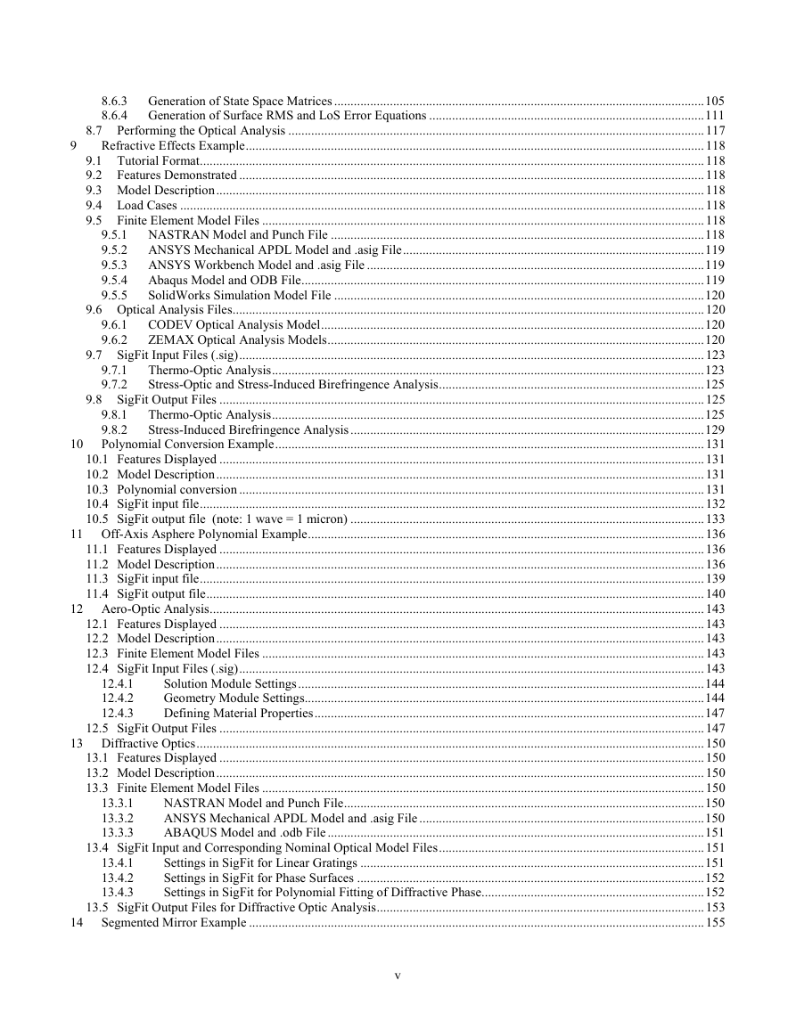
9 10 14 9.6.1 9.6.2 9.7.1 9.7.2 8.6.3 Generation of State Space Matrices ................................................................................................................. 105 8.6.4 Generation of Surface RMS and LoS Error Equations .................................................................................... 111 8.7 Performing the Optical Analysis ............................................................................................................................... 117 Refractive Effects Example ............................................................................................................................................ 118 9.1 Tutorial Format .......................................................................................................................................................... 118 9.2 Features Demonstrated .............................................................................................................................................. 118 9.3 Model Description ..................................................................................................................................................... 118 9.4 Load Cases ................................................................................................................................................................ 118 9.5 Finite Element Model Files ....................................................................................................................................... 118 9.5.1 NASTRAN Model and Punch File .................................................................................................................. 118 9.5.2 ANSYS Mechanical APDL Model and .asig File ............................................................................................ 119 9.5.3 ANSYS Workbench Model and .asig File ....................................................................................................... 119 9.5.4 Abaqus Model and ODB File ........................................................................................................................... 119 9.5.5 SolidWorks Simulation Model File ................................................................................................................. 120 9.6 Optical Analysis Files................................................................................................................................................ 120 CODEV Optical Analysis Model ..................................................................................................................... 120 ZEMAX Optical Analysis Models ................................................................................................................... 120 9.7 SigFit Input Files (.sig) .............................................................................................................................................. 123 Thermo-Optic Analysis .................................................................................................................................... 123 Stress-Optic and Stress-Induced Birefringence Analysis ................................................................................. 125 9.8 SigFit Output Files .................................................................................................................................................... 125 9.8.1 Thermo-Optic Analysis .................................................................................................................................... 125 9.8.2 Stress-Induced Birefringence Analysis ............................................................................................................ 129 Polynomial Conversion Example ................................................................................................................................... 131 10.1 Features Displayed .................................................................................................................................................... 131 10.2 Model Description ..................................................................................................................................................... 131 10.3 Polynomial conversion .............................................................................................................................................. 131 10.4 SigFit input file .......................................................................................................................................................... 132 10.5 SigFit output file (note: 1 wave = 1 micron) ............................................................................................................ 133 11 Off-Axis Asphere Polynomial Example ......................................................................................................................... 136 11.1 Features Displayed .................................................................................................................................................... 136 11.2 Model Description ..................................................................................................................................................... 136 11.3 SigFit input file .......................................................................................................................................................... 139 11.4 SigFit output file ........................................................................................................................................................ 140 12 Aero-Optic Analysis ....................................................................................................................................................... 143 12.1 Features Displayed .................................................................................................................................................... 143 12.2 Model Description ..................................................................................................................................................... 143 12.3 Finite Element Model Files ....................................................................................................................................... 143 12.4 SigFit Input Files (.sig) .............................................................................................................................................. 143 Solution Module Settings ............................................................................................................................ 144 Geometry Module Settings.......................................................................................................................... 144 Defining Material Properties ....................................................................................................................... 147 12.5 SigFit Output Files .................................................................................................................................................... 147 13 Diffractive Optics ........................................................................................................................................................... 150 13.1 Features Displayed .................................................................................................................................................... 150 13.2 Model Description ..................................................................................................................................................... 150 13.3 Finite Element Model Files ....................................................................................................................................... 150 NASTRAN Model and Punch File .............................................................................................................. 150 ANSYS Mechanical APDL Model and .asig File ....................................................................................... 150 ABAQUS Model and .odb File ................................................................................................................... 151 13.4 SigFit Input and Corresponding Nominal Optical Model Files ................................................................................. 151 Settings in SigFit for Linear Gratings ......................................................................................................... 151 Settings in SigFit for Phase Surfaces .......................................................................................................... 152 Settings in SigFit for Polynomial Fitting of Diffractive Phase.................................................................... 152 13.5 SigFit Output Files for Diffractive Optic Analysis .................................................................................................... 153 Segmented Mirror Example ........................................................................................................................................... 155 13.4.1 13.4.2 13.4.3 12.4.1 12.4.2 12.4.3 13.3.1 13.3.2 13.3.3 v
14.4.1 14.1 Features Displayed .................................................................................................................................................... 155 14.2 Model Description ..................................................................................................................................................... 155 14.3 Load Condition .......................................................................................................................................................... 156 14.4 FE Model File ............................................................................................................................................................ 156 NASTRAN Model and Punch File .............................................................................................................. 156 14.5 Surface Deformation Analysis with Segments .......................................................................................................... 156 Analysis Definition for Surface Deformation Analysis with Segments ...................................................... 156 Output for Surface Deformation Analysis with Segments .......................................................................... 157 14.6 Racking Analysis with Segments .............................................................................................................................. 162 Analysis Definition of Racking Analysis .................................................................................................... 162 14.7 Line-of-Sight Error in Random Response Analysis with Segments .......................................................................... 167 Analysis Definition for Line-of-Sight Error Analysis With Segments........................................................ 167 Output of Line-of-Sight Error Analysis with Segments .............................................................................. 168 14.5.1 14.5.2 14.6.1 14.7.1 14.7.2 vi
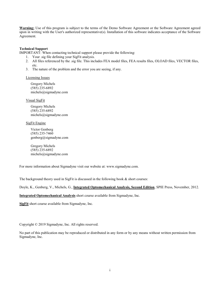
Example 1 SigFit 2019R1b 1 Surface Fitting Example 1.1 Tutorial Format This example is also in a SigFit Workshop tutorial format with PDF presentation charts guiding the user through the example. Please find this alternative form in a separate download. Finite Element Software NASTRAN ANSYS Workbench SIMULIA ABAQUS Path To Tutorial Files EX_1PolynomialFittingExample folder in SigFit_Tutorials_NASTRAN.zip EX_1PolynomialFittingExample folder in SigFit_Tutorials_ANSYSWB.zip EX_1PolynomialFittingExample folder in SigFit_Tutorials_SIMULIAAbaqus.zip 1.2 Features Demonstrated This example shows the application of SigFit to polynomial fitting of deformed surfaces. This example shows the basic manner in which SigFit interfaces with the finite element model and how the user may request various output results. Other key features emphasized are: 1. Finite Element Model Output Requirements: Requests and definitions which must be made within the finite element software to support surface deformation analysis in SigFit are shown. 2. Deformed Surface Output: Various forms of output from surface fitting are illustrated. These include best fit rigid body motions, best fit polynomial coefficients, and best fit radius of curvature. 3. Coordinate Systems: Nodal locations and displacements are expressed in a local cylindrical coordinate system requiring SigFit to transform data to another local vertex coordinate system. 4. Polynomial Fitting: Polynomial fitting of the surface displacement is performed with various sets of polynomials including Zernike polynomials. 5. Result Files for Optical Analysis: Generation of files importable to CODEV, OSLO, and ZEMAX are illustrated. 1.3 Example Model Description A parabolic mirror supported on 3 points is analyzed for common load conditions. The geometry of the mirror and mounting layout are shown in Figure 1-1. The mounts are constrained only in the directions parallel to the parent optical axis of the mirror and in the circumferential directions around this axis. 1
分享到:
收藏