Voltage-fed permanent-magnet stepper motor
control via position-only feedback
P. Krishnamurthy and F. Khorrami
Abstract: A robust adaptive nonlinear dynamic controller is designed to achieve practical
stabilisation for position tracking error of a voltage-fed permanent-magnet stepper motor. The
control design is an output-feedback design that utilises only rotor position measurements. Rotor
velocity and stator phase currents are not available for feedback. Furthermore, the only motor
parameter that is required to be known is the time constant of the electrical subsystem. Adaptations
are utilised so that no other knowledge of motor parameters is required. The proposed controller is a
fourth-order dynamic compensator and is robust to load torques, friction, cogging forces and other
disturbances satisfying certain bounds. Practical stabilisation of the tracking error is achieved with
global boundedness of all closed-loop signals. Furthermore, under the condition that the torque
disturbances are locally linearly bounded by a function of rotor position, the designed controller
achieves asymptotic stabilisation of the rotor position. These results can also be extended to other
classes of motors.
1 Introduction
Closed-loop control schemes for permanent-magnet (PM)
stepper motors have been extensively investigated [1 – 3].
The majority of results utilise full state feedback. Position
control was achieved in [4, 5] using feedback linearisation
relying on an exact knowledge of motor dynamics and
parameters. To handle certain parametric uncertainties,
adaptations were introduced with a feedback linearising
control
law in [6]. Adaptive state feedback was also
addressed in [7]. An adaptive controller robust to parametric
and dynamic uncertainties such as nonsinusoidal flux
density due to geometric imperfections of the motors was
presented in [8].
Partial state feedback designs utilising measurement of
various subsets of the state are also of interest. We will
consider the case where only the rotor position is measured.
Although current sensors are usually part of the inner
current loop in the motor amplifiers, their outputs are not
easily accessible to the user without tapping and possibly
modifying the amplifier circuitry. The tachometer signals
are usually noisy and it is desirable to eliminate velocity
measurement. These considerations have fuelled interest in
the output-feedback control problem eliminating rotor
velocity and stator current measurements. To obviate rotor
velocity measurement, a nonlinear speed observer utilising
position and current measurements with linear error
dynamics was constructed in [9, 10]. These results were
extended to the adaptive case in [11] with the rotor position
and stator winding currents being measured. In [12], a
current-level output
to
parametric and dynamic uncertainties such as friction,
load torque and cogging torque was designed.
feedback controller
robust
q IEE, 2004
IEE Proceedings online no. 20040622
doi: 10.1049/ip-cta:20040622
Paper first received 27th August 2003 and in revised form 1st April 2004
The authors are with the Control/Robotics Research Laboratory (CRRL),
Department of Electrical and Computer Engineering, Polytechnic
University, Six Metrotech Center, Brooklyn, NY 11201, USA
the electromechanical parameters of
The output-feedback control problem without current
measurements has been investigated in recent years. In [13],
under the assumption that lower and upper bounds for all
motor parameters are known, a controller utilising the rotor
position and velocity was proposed. In [14], a robust
adaptive controller was designed utilising the rotor position
and velocity for feedback without requiring any knowledge
of
the motor.
This design was extended to the nonsinusoidal flux
distribution case in [15]. However, in this more general
case, it was necessary to assume knowledge of upper and
lower bounds on the time constant of the electrical
subsystem. A controller which requires only position
measurements was designed in [16] assuming exact
knowledge of all motor parameters. In [17], a robust
controller was designed using only position measurements
and assuming that upper and lower bounds for all motor
parameters are known.
We will address the problem of designing a robust
adaptive controller for voltage-fed PM stepper motors.
Only rotor position measurements are used for feedback.
This extends our earlier results in [14] where the rotor
position and velocity needed to be measured. Further-
more, the only motor parameter that is required in the
controller design is the time constant of the electrical
the other parameters is
subsystem. No knowledge of
in [14] does not need this
required. The controller
parameter to be known. However,
in the position-only
feedback case, there are no techniques currently available
results with this parameter being
to obtain global
completely unknown.
interesting to note that
extending the design of [14] to the nonsinusoidal flux
distribution case [15] required assuming that upper and
lower bounds were available on the electrical
time
It appears that uncertainty in the electrical
constant.
time constant
is a fundamental obstacle in achieving
global output-feedback results for this class of systems.
The control design is complicated by the lack of
theoretical tools in the nonlinear control literature that can
be applied to this system since it is not transformable to
any adaptive nonlinear output-feedback canonical form.
Therefore, an essentially different design methodology has
is
It
IEE Proc.-Control Theory Appl., Vol. 151, No. 4, July 2004
499
�
to be explored. Techniques developed here can be utilised to
generalise the standard nonlinear output-feedback canonical
form along the lines in our work in [18, 19]. These
techniques can be extended to the control design for other
types of motors. The controller proposed is a fourth-order
dynamic compensator and achieves global stability with
practical stabilisation of the tracking error. Furthermore, if
the torque disturbances can be bounded by a function of the
rotor position that is locally linearly bounded around the
origin,
the designed controller guarantees asymptotic
stabilisation.
2 Electromechanical model and problem
statement
The mechanical dynamics of a PM stepper with two phases
may be modelled in the state space as follows [20, 21]:
_yy ¼ o
_oo ¼ 1
J
ðt � Do � tlÞ
ð1Þ
where y is the rotor position, o the rotor speed, t the
electromagnetic torque, D the viscous damping factor, and
tl the sum of all load torques, cogging forces, and other
modelling uncertainties. J is the rotor inertia. t is a function
of currents and rotor position given by
iT @L
@y
i
ð2Þ
with the symmetric positive definite inductance matrix L
and current vector i defined as
For simplicity, assume R1 ¼ R2 ¼ R: The flux linkages
are given by:
f¼ ½ f1 f2 ff T ¼ Li
ð10Þ
Using (2) – (10), the torque and the current dynamics are
obtained as (note that the last term involving i2
in the
f
torque equation represents the disturbance torque due to
cogging):
t ¼ �i1ifLm1Nr sinðNryÞ þ i2ifLm1Nr cosðNryÞ
� 2Lf4Nr sinð4NryÞi2
f
_ii1 ¼ 1
L0
_ii2 ¼ 1
L0
fu1 � i1R þ ifoNrLm1 sinðNryÞg
fu2 � i2R � ifoNrLm1 cosðNryÞg
It will be convenient to define the state variables:
x2 ¼ o
x1 ¼ y
x3 ¼ L0i1
x4 ¼ L0i2
ð11Þ
ð12Þ
ð13Þ
ð14Þ
The dynamics of the PM stepper motor can be written
as:
_xx1 ¼ x2
_xx2 ¼ k1½�x3 sinðNrx1Þ þ x4 cosðNrx1Þ � k2x2 � tn
_xx3 ¼ �gx3 þ k3x2 sinðNrx1Þ þ u1
_xx4 ¼ �gx4 � k3x2 cosðNrx1Þ þ u2
where
ð3Þ
k1 ¼ ifNrLm1
JL0
k3 ¼ ifLm1Nr
tn ¼ 1
J
k2 ¼ D
J
g ¼ R
L0
ðtl þ 2Lf4Nri2
f sinð4Nrx1ÞÞ
ð15Þ
ð16Þ
the
t ¼ 1
2
2
4
3
5
L ¼ L11 L12 L1f
L12 L22 L2f
L1f
Lff
i ¼ i1
½
L2f
if
i2
T
ð4Þ
where i1 and i2 are the stator phase currents and if is the
fictitious constant rotor current provided by the permanent
magnet. Ljj; j ¼ 1; 2;
is the self-inductance of the jth
winding, j ¼ 1; 2: L12 is the mutual inductance between
the two windings. Ljf; j ¼ 1; 2; is the mutual inductance
between the jth phase and the fictitious rotor winding. Lff is
the self-inductance of the fictitious rotor winding. Under the
usual assumptions of sinusoidal flux distribution and that
the variations of the stator self-inductance with position
and the mutual inductance between the stator windings are
negligible, the terms in the inductance matrix are:
L11 ¼ L22 ¼ L0 L12 ¼ 0
L1f ¼ Lm0 þ Lm1 cosðNryÞ
L2f ¼ Lm0 þ Lm1 sinðNryÞ
Lff ¼ Lf0 þ Lf4 cosð4NryÞ
ð5Þ
ð6Þ
ð7Þ
ð8Þ
where Nr is the integer number of rotor teeth. The electrical
subsystem is modelled as:
uj ¼ Rjij þ dfj
dt
j ¼ 1; 2
ð9Þ
where uj; fj and Rj are the voltage, flux linkage and
resistance in the jth phase, respectively.
The control design will be carried out under
following assumptions:
Assumption 1: g is a known positive constant. k1; k2 and
k3 are unknown constants.
Assumption 2: tn can be bounded as:
jtnj2 � kðr0 þ rðy2ÞÞ ¼ kðr0 þ rðx2
1ÞÞ
ð17Þ
where k and r0 are unknown constants and r is a known
class K1 function. Note that a continuous function a :
½0; aÞ ! ½0;1Þ is said to belong to class K if it is strictly
increasing and að0Þ ¼ 0: It is said to belong to class K1
if a ¼ 1 and aðrÞ ! 1 as r ! 1:
Remark 1: From the definition of tn in (16), it is seen that tn
satisfies the bound in (17) if tl does. This implies that
position-dependent load torques (which can also depend on
velocity in a bounded manner) can be handled, e.g. a load
depending on gravity such as N sinðyÞ: The proposed
controller design also compensates for friction torques Do
with unknown friction coefficient D. Furthermore, any load
torque component of form q fðy; oÞ with f being a known
function and q an unknown parameter can also be handled
500
IEE Proc.-Control Theory Appl., Vol. 151, No. 4, July 2004
�
through a straightforward modification of the advocated
design.
We now intend to address the problem of controller
design with the control objective being to make y practically
track a given thrice-differentiable bounded reference signal
yrefðtÞ with bounded derivatives up to third-order while
keeping all closed-loop signals bounded given that only y is
available for feedback and only parameter g is known, i.e. we
seek to design dynamic control laws for u1 and u2 utilising
measurement of x1 to make the tracking error ðx1 � yrefÞ
converge to ½��e; �e for any arbitrary prespecified �e; while
keeping all closed-loop signals bounded.
3 Observer design
Since the system, (15), is not transformable to any output
feedback canonical form,
the standard observer design
techniques cannot be used. A reduced-order observer is
now proposed which generates estimates of the unmea-
sured states, x2; x3 and x4: The observer structure is
given by:
_^xx^xx2 ¼ �a1 ^xx2 � ^xx3 sinðNrx1Þ þ ^xx4 cosðNrx1Þ
_^xx^xx3 ¼ �g^xx3 þ u1
_^xx^xx4 ¼ �g^xx4 þ u2
ð18Þ
where a1 is a positive design parameter. The observer
errors are defined as:
x2 þ a2x1
e2 ¼ ^xx2 � 1
k1
e3 ¼ ^xx3 � x3 � k3
Nr
e4 ¼ ^xx4 � x4 � k3
Nr
cosðNrx1Þ
sinðNrx1Þ
ð19Þ
where a2 ¼ ða1 � k2Þ=k1 is a (not necessarily positive)
constant.
Remark 2: It is seen from the observer error definitions in
(19) that the actual estimates for x2; x3 and x4 are k1ð^xx2 þ
a2x1Þ; ^xx3 � ðk3=NrÞ cosðNrx1Þ; and ^xx4 � ðk3=NrÞ sinðNrx1Þ;
respectively. These
cannot be
implemented since they depend on the unknown parameters.
However, since our main objective is controller design, we
do not need to actually realise estimates for the unmeasured
states. It will be shown that the dynamic signals that are
generated from the dynamics in (18) are sufficient to achieve
the control objective.
estimates
‘virtual’
The observer error dynamics are:
_ee2 ¼ � a1e2 � e3 sinðNrx1Þ þ e4 cosðNrx1Þ
tn
þ a1a2x1 þ 1
k1
_ee3 ¼ � ge3 � gk3
cosðNrx1Þ
Nr
_ee4 ¼ � ge4 � gk3
sinðNrx1Þ
Nr
�
e3 þ k3
Nr
2 þ 6
e2
ga1
Vo ¼ 1
2
�
Differentiating (21):
The stability of this observer can be analysed using the
Lyapunov function:
�
�
ð20Þ
2þe2
4
ð21Þ
�
tn
�
k3
Nr
� k3
Nr
cosðNrx1Þ
ð22Þ
e2
2
2þ2a1a2
2x2
e2
1
h
½1�cosðNrx1Þ2
�
þ c minðl;1Þ
�
ð23Þ
ð24Þ
_VVo¼e2 �a1e2�e3sinðNrx1Þþe4cosðNrx1Þþa1a2x1þ 1
k1
�
�
cosðNrx1Þ
4
�
�
tn
�
þ12
a1
�
þ12
a1
�
�
�
e3þ k3
þ 12
ga1
Nr
�
�
þe4 �ge4�gk3
Nr
e3þ k3
�
Nr
�
��
�ge3�gk3
Nr
�
�
sinðNrx1Þ
2þe2
¼�a1e2
2�12
�
�
a1
þe2½�e3sinðNrx1Þþe4cosðNrx1Þ
�
e3þ k3
þe2 a1a2x1þ 1
k1
Nr
sinðNrx1Þ
e4 �k3
�
�
�
Nr
�
�
e3þ k3
Nr
2þe2
�
�
��a1e2
2�12
a1
e3þ k3
Nr
sin2ðNrx1Þþa1
2þ 2k2
e2
a1N2
�
�
�
2þ 2
t2
e2
n
a1k2
8
i
2þe2
e3þ k3
þ 6
a1
Nr
�
�
þsin2ðNrx1Þ
� �
�
��a1
2� 2
e2
a1
2
£ x2
1þr x2
þ 6k2
a1N2
�
2þe2
þ 4
a1
þa1
þa1
2þe2
�
�
8
8
1
4
3
r
4
3
r
1
4
�
e3þ k3
Nr
þr0
�
þ a1
8
4
where
3
1
c ¼
minðl; 1Þ max 2a1a2
2 þ 8k2
;
a1
with l � 1 being a positive design freedom.
the observer error
states ðe2; e3 þ ðk3=NrÞ; e4Þ are rendered input-to-state-
practically-stable [22] with respect to x1:
From (24),
seen that
2k
a1k2
ð25Þ
is
it
1
4 Controller design
In this Section, the control inputs, u1 and u2; are designed
using robust adaptive observer backstepping technique [23]
applied to the subsystem:
_xx1 ¼ k1ð^xx2 þ a2x1 � e2Þ
_^xx^xx2 ¼ �a1 ^xx2 � ^xx3 sinðNrx1Þ þ ^xx4 cosðNrx1Þ
_^xx^xx3 ¼ �g^xx3 þ u1
_^xx^xx4 ¼ �g^xx4 þ u2
ð26Þ
The backstepping design proceeds by considering lower-
dimensional subsystems and designing virtual control inputs
(or equivalently, state transformations). The virtual control
input in the first step is ^xx2: In the second step, both ^xx3 and ^xx4
appear in the derivative of ^xx2 and are used as virtual control
inputs. The virtual control law designed in the second step
can be interpreted as a virtual control law for (scaled) torque
IEE Proc.-Control Theory Appl., Vol. 151, No. 4, July 2004
501
�
1 þ y2
z2
ref
where
_VV2 � � �0
1z1n1 � z2n2 þðb1 þ b2 � ^bb� b4Þb2 þð _^bb^bbþ s ^bbÞb4
þ z2fb3 � ^xx3 sinðNrx1Þþ ^xx4 cosðNrx1Þgþ 2lz2
þ ln2
¼ � �0
1ðz1Þþ 2�e2
1z1n1 � z2n2 þðb1 þ b2 � ^bb� b4Þb2 þð _^bb^bbþ s ^bbÞb4
2 þ d2
1
þ z2 cosðNrx1Þðb3 cosðNrx1Þþ ^xx4Þþ 2�e2
þ z2 sinðNrx1Þðb3 sinðNrx1Þ� ^xx3Þþ 2lz2
2 þ d2
1 þ ln2
1ðz1Þ
¼ � �0
1z1n1 � z2n2 þðb1 þ b2 � ^bb� b4Þb2 þð _^bb^bbþ s ^bbÞb4
� z2 sinðNrx1Þz3 þ z2 cosðNrx1Þz4 þ 2lz2
þ 2�e2
2 þ d2
1 þ ln2
1ðz1Þ
ð35Þ
i
1Þ2z3
1
1Þ2
z2
2
1ð1 þ �0
i
1Þ2
b3ð ^bb; z1; z2; ^xx2; _yyrefÞ ¼ �0
1
2
ref
1
2l
þ k2
1
4�
1a2
þ k2
2l
b2 ¼ k1 þ k2
ref þ _yy2
d2 ¼ 2y2
h
1 þ �02
b2ð ^bb; z1; z2Þ ¼ ð�0
1Þz2
^bb2ð1 þ �0
þ b1 þ b2
1 þ b2
_yyref þ �0
1z1 � a1 ^xx2 � b1
h
þ z2½ ^bb þ ð1 þ �0
1Þz1z2
^bb2ð1 þ �0
1 þ b2
� b1 þ b2
� s ^bbð1 þ �0
1Þz1 þ n2ðz2Þ
1Þz1
b4ðz1; z2Þ ¼ z2ð1 þ �0
1
1
z3 ¼ ^xx3 � b3 sinðNrx1Þ
z4 ¼ ^xx4 þ b3 cosðNrx1Þ
where
the control
estimate along with a commutation scheme. In the third
inputs u1 and u2 appear and can be
step,
designed.
Step 1: For the first step, a Lyapunov function:
� �
�1 z2
1
V1 ¼ 1
2k1
ð27Þ
is used where z1 ¼ x1 � yref and �1 is a class K1 function to
� �
be chosen later in the design process. Differentiating (27)
(note that in the following, f 0ðsÞ denotes @fðsÞ=@sÞ :
� �
z1ð^xx2 þ a2x1 � e2Þ � 1
k1
1 z2
1
z1
ð28Þ
Straightforward algebra yields the inequalities:
_yyref�0
� �
� �
� �
1 þ a2
�02
2
1 z2
z2
1
4
� �
1 þ �e2
z2
1 þ _yy2
z2
� �
�
2
1 z2
1
1 z2
1
a2�0
��0
1 z2
1
_yyref�0
� �
_VV1 ¼ �0
� �
� �
z1x1 � �aa2�0
1 z2
1
� �
�02
z1e2 � 1
1 z2
1
4�
�02
z1 � 1
1 z2
1
4k2
1
�
� �
z1 ^xx2 þ b1 �0
�
b1 ¼ max �aa2;
1 z2
1
1 z2
1
� 1
ð29Þ
k1
where �aa2 ¼ ða1 þ k2Þ=k1 and � ¼ ½a1=ð16cÞ: Thus, (28)
reduces to:
_VV1 � �0
2 þ d1 ð30Þ
1 þ �e2
z2
1 z2
1
1 z2
1
ref
a2
2
4
ref
z1z2
�
� �
z1n1ðz1Þ þ �0
þ ðb1 � ^bbÞ �0
1 z2
1
ref þ _yy2
d1 ¼ y2
þ 1
þ 1
ð31Þ
4k2
4�
1
1ÞÞz1 þ n1ðz1Þ where ^bb is a
Define z2 ¼ ^xx2 þ ^bbð1 þ �0
1ðz2
dynamic
in counteracting the
� �
effect of the unknown b1 and n1 is a function which satisfies
sn1ðsÞ � 08s 2 R: Therefore, (30) may be rewritten as:
� �
signal which aids
_VV1 � � �0
� �
�
1 z2
1
1 z2
1
2 þ d1
1 þ �e2
z2
� �
n
ð32Þ
Step 2: A new Lyapunov function is defined as V2 ¼
V1 þ ð1=2Þz2
_VV2 � � �0
þ z2
þ ^xx4 cosðNrx1Þ � a1 ^xx2 þ b1ð ^bb; z1Þ
�
� �
� ½k1ð^xx2 þ a2x1 � e2Þ � _yyref
�
�
� �
þ _^bb^bb 1 þ �0
1 z2
1
þ ðb1 � ^bbÞ �0
2 which satisfies:
z1n1ðz1Þ þ �0
�^xx3 sinðNrx1Þ
o
�
� �
z1z2 þ �e2
2 þ d1
þ �02
ð33Þ
1 z2
1
1 z2
1
1 z2
1
1 z2
1
þ �02
1 z2
1
� �
z2
1
z1
þ �02
�
where, for notational convenience, we have introduced:
�
� �
� �
�
b1ð ^bb; z1Þ ¼ ^bb 1 þ �0
1 z2
1
þ 2z2
1�00
1 z2
1
þ n0
1ðz1Þ
ð34Þ
We shall also drop the arguments of b1; �1; etc. for ease and
clarity of notation.
Remark 3: b1 is non-negative if ^bb; �0
1 are non-
negative. The final choice of the design freedoms will
ensure that b1 � 0:
1 and n0
1; �00
Rearranging terms and overbounding, (33) reduces to
(for notational convenience, we drop arguments of
functions whenever no confusion will result):
502
ð36Þ
s is a positive design parameter, and n2 ¼ c2z2 with c2
being a positive design parameter.
Step 3: This is the last step of backstepping. In this step, the
control inputs, u1 and u2; will be designed. For this step, a
new Lyapunov function is defined as:
3 þ 1
z2
2
ð37Þ
z2
4
Before differentiating this Lyapunov function, it will be
useful to find _bb3:
V3 ¼ V2 þ 1
2
�
k1ð^xx2 þ a2x1 � e2Þ
n
@b3
@z2
þ b1
�
_bb3 ¼ b5 þ @b3
@z1
where
b5 ¼ @b3
@ ^bb
þ^xx4 cosðNrx1Þ þ _^bb^bbð1 þ �0
_yyref þ @b3
@z2
_^bb^bb � @b3
@z1
�a1 ^xx2 � ^xx3 sinðNrx1Þ
o
1Þz1 � b1
þ @b3
@ _yyref
f�a1 ^xx2 � ^xx3 sinðNrx1Þ þ ^xx4 cosðNrx1Þg
_yyref
þ @b3
@ ^xx2
ð38Þ
€yyref
ð39Þ
The partial derivatives of b3 in (38) and (39) are evaluated
with b1 and b3 interpreted as symbolic functions of the
indicated arguments, i.e. algebraic relationships between the
arguments such as the one between z2 and ^xx2 are not utilised
IEE Proc.-Control Theory Appl., Vol. 151, No. 4, July 2004
�
in evaluating the partial derivatives. Differentiating (37):
_VV3 � � �0
1z1n1 � z2n2 þ ðb1 þ b2 � ^bb � b4Þb2 þ ð _^bb^bb þ s ^bbÞb4
�
1ðz1Þ
k1
�
�
þ b1
�
� ð^xx2 þ a2x1 � e2Þ
�
�
1 þ ln2
� z2 sinðNrx1Þz3 þ z2 cosðNrx1Þz4 þ 2lz2
þ z3 �g^xx3 þ u1 � b5 þ @b3
@b3
@z1
@z2
sinðNrx1Þ
�
�
þ z4 �g^xx4 þ u2 þ b5 þ @b3
@z1
cosðNrx1Þ
þ b1
�
�b3Nr sinðNrx1Þk1ð^xx2 þ a2x1 � e2Þ
�b3Nr cosðNrx1Þk1ð^xx2 þ a2x1 � e2Þ
� k1ð^xx2 þ a2x1 � e2Þ
@b3
@z2
�
�
�
þ 2�e2
2 þ d2
ð40Þ
Defining
�
�
b6 ¼ @b3
@z1
b7 ¼ @b3
@z1
þ b1
þ b1
@b3
@z2
@b3
@z2
�
�
�
1a2
þ k2
2l
h
þ k2
þ k2
b3 ¼ k2
1
1
1
4�
2l
c2
6 1þ ^bb2 1þ �02
b8 ¼ z2
3b2
2
1
�
i
d3 ¼ 4y2
þ z2
h
ref þ _yy2
7 1þ ^bb2 1þ �02
4b2
�
ref
1
�
i
ð43Þ
Note that bi; i¼ 1; . . . ; 8 depend only on the states that are
available and do not involve any unknown parameters. The
control inputs, u1 and u2; are now specified as:
u1 ¼ z2 sinðNrx1Þþ gb3 sinðNrx1Þþ b5 sinðNrx1Þ
� n3ðz3Þ
�ð ^bbþ b4Þz3b2
1
u2 ¼ � z2 cosðNrx1Þ� gb3 cosðNrx1Þ� b5 cosðNrx1Þ
�
�
h
6 1þ ^bb2 1þ �02
h
7 1þ ^bb2 1þ �02
�
i
�
i
1
� n4ðz4Þ
�ð ^bbþ b4Þz4b2
ð44Þ
where n3 and n4 are functions such that sniðsÞ� cis28s2R;
i¼ 3; 4 with c3 and c4 being positive design freedoms.
�
�
Using (44), (42) simplifies to:
�
�
_VV3 � � �0
1z1v1 � 1
z2v2 � z3v3 � z4v4 � g z2
2
b4 þ ðb1 þ b2 þ b3 � ^bb � b4Þðb2 þ b8Þ
þ _^bb^bb þ s ^bb
þ 6lz2
1ðz1Þ þ 4�e2
1 þ 3lv2
2 þ d3
3 þ z2
4
ð45Þ
_^bb^bb ¼ �s ^bb þ b2 þ b8
ð46Þ
5 Stability analysis
Stability of the closed-loop system is analysed using the
composite Lyapunov function:
whose derivative satisfies
_VV � � �0
4
Vo
�
�
ð47Þ
3 þ z2
1z1n1 � 1
2
V ¼ V3 þ 1
2
ð ^bb � b1 � b2 � b3Þ2 þ 16�
a1
�
z2n2 � z3n3 � z4n4 � g z2
þ ðb1 þ b2 þ b3 � ^bb � b4Þðb2 þ b8Þ þ ð _^bb^bb þ s ^bbÞb4
�
�
�
� �
þ 6lz2
2 þ d3 þ ð ^bb � b1 � b2 � b3Þ _^bb^bb
1ðz1Þ þ 4�e2
�
�
þ lx2
� 8�e2
e3 þ k3
1 þ r0 þ lr x2
Nr
�
�
�
� 4�e2
3 þ z2
z2n2 � z3n3 � z4n4 � g z2
2þe2
e3 þ k3
Nr
1 þ 3ln2
2 � 32�
a2
1
1z1n1 � 1
2
�
ð ^bb � b1 � b2 � b3Þ2 � 32�
a2
1
þ d4
1 þ 3ln2
�
ref þ r 4y2
�
1ðz1Þ þ lr 4z2
�
ðb1 þ b2 þ b3Þ2
ð48Þ
ð49Þ
ref þ r0 þ s
2þe2
þ _yy2
�
ref
4
1
4
2
4
1
� � �0
� s
þ 8lz2
2
where
d4 ¼ 6y2
2
Before proceeding, we need the following lemma.
Lemma 1: Given any class K1 function, FðsÞ;
possible to find a class K1 function,
s ! 0þ; and a constant, s � 0; to satisfy:
is
~FFðsÞ ¼ O½s as
it
sinðNrx1Þ þ b3Nr cosðNrx1Þ
cosðNrx1Þ � b3Nr sinðNrx1Þ
ð41Þ
The dynamics for ^bb are designed as:
and overbounding, (40) reduces to:
1
1
�
�
þ z4
�
i
h
6 1þ ^bb2 1þ �02
3b2
z2
_VV3 � � �0
z2n2 þðb1 þ b2 � ^bb� b4Þb2 þð _^bb^bbþ s ^bbÞb4
1z1n1 � 1
�
2
2 þ d3
1 þ 3ln2
1ðz1Þþ 4�e2
þ 6lz2
i�
�
�
h
þ z3
�z2 sinðNrx1Þ� g^xx3 þ u1 � b5 sinðNrx1Þ
�
6 1þ ^bb2 1þ �02
þ ^bbz3b2
i�
�
h
z2 cosðNrx1Þ� g^xx4 þ u2 þ b5 cosðNrx1Þ
�
7 1þ ^bb2 1þ �02
þ ^bbz4b2
i�
�
h
þðb3 � ^bbÞ
7 1þ ^bb2 1þ �02
4b2
n
� � �0
z2n2 þðb1 þ b2 þ b3 � ^bb� b4Þðb2 þ b8Þ
1z1n1 � 1
h
2
þ z3
6 1þ ^bb2 1þ �02
þð ^bbþ b4Þz3b2
h
þ z4
z2 cosðNrx1Þ� g^xx4 þ u2
7 1þ ^bb2 1þ �02
þb5 cosðNrx1Þþð ^bbþ b4Þz4b2
þ 6lz2
�z2 sinðNrx1Þ� g^xx3 þ u1 � b5 sinðNrx1Þ
2 þ d3 þð _^bb^bbþ s ^bbÞb4
1ðz1Þþ 4�e2
1 þ 3ln2
�
io
io
þz2
n
�
�
�
�
1
1
1
1
ð42Þ
where
IEE Proc.-Control Theory Appl., Vol. 151, No. 4, July 2004
503
�
FðsÞ � ~FFðsÞ þ s 8s > 0
�
Proof: s ¼ sups�1 FðsÞ and:
~FFðsÞ ¼ Fð1Þs
FðsÞ
for s � 1
for s > 1
ð50Þ
ð51Þ
satisfy (50)
A
Applying lemma 1, we find a class K1 function, ~rrðsÞ; and
a positive constant, cr; such that ~rrðsÞ ¼ O½s as s ! 0þ and
ð52Þ
rðsÞ � ~rrðsÞ þ cr
1
2
�
Thus, (48) reduces to:
_VV � � �0
� s
þ 8lz2
�
1ðz1Þ þ l ~rr 4z2
�
1z1n1 � 1
2
�
ð ^bb � b1 � b2 � b3Þ2 � 32�
a2
1
1 þ 3ln2
þ d5
�
where
d5 ¼ 6y2
ref þ r 4y2
� �
ref þ r0 þ s
� �
�
z1n1ðz1Þ � c1�1 z2
� 2l 8z2
1 þ 3n2
with a constant c1 > 0 and with �0
being non-negative for all z1 2 R:
�0
1 z2
1
þ _yy2
ref
2
1
Finally, �1 and n1 are chosen to ensure that:
ðb1 þ b2 þ b3Þ2 þ cr
ð54Þ
�
�
�
1ðz1Þ þ ~rr 4z2
1ðz2
1ðz2
1Þ; �00
1
1Þ; and n0
ð55Þ
1ðz1Þ
�
z2n2 � z3n3 � z4n4 � g z2
�
�
�
3 þ z2
e3 þ k3
Nr
4
�
� 4�e2
2þe2
2
4
ð53Þ
1
1
�
�
�
1 z2
1
m z2
1
c1�0
1ðz2
ð56Þ
1Þ; �00
(55) reduces to:
¼ 2l 8 þ 3c2
Remark 4: In this remark, we provide a proof
that
functions �1 2 K1 and n1 can be chosen such that (55)
is satisfied with c1 being a positive constant, and with
1Þ and n0
1ðz1Þ being non-negative for all
1ðz2
�0
z1 2 R: Choosing, for instance, n1ðz1Þ ¼ c1z1 with c1 > 0;
� �
�
�
and defining:
� �
�
1 þ ~rr 4z2
z2
� �
1 � m z2
z2
ð57Þ
Note that mðsÞ is continuous and mðsÞ ¼ O½s as s ! 0þ:
Hence, a smooth positive nondecreasing function ~mm can
s 2 ½0;1Þ: A
R
be chosen such that
smooth positive nondecreasing function ~mmc can be chosen
such that ~mmcðsÞ � ~mm0ðsÞ for s 2 ½0;1Þ: Choosing �1ðsÞ ¼
0 ~mmcðwÞdw; the inequalities c1�1ðsÞ � mðsÞ
ðs=c1Þ½ ~mmð0Þ þ
1ðsÞs ¼ c1�1ðsÞ þ s2 ~mmcðsÞ � c1�1ðsÞ are satisfied
and c1�0
1ðsÞ
for s 2 ½0;1Þ: With this choice of �1; the function �0
is positive for all s 2 ½0;1Þ: Moreover, since �0
1 is a
1ðsÞ is positive for
monotonically increasing function, �00
positive s. Furthermore, note that with this choice of �0
1Þz1n1ðz1Þ ¼ c1�0
1ðz2
1Þz2
and n1; the term �0
1
1 is a class K1
function of z2
1:
s ~mmðsÞ � mðsÞ
1ðz2
for
1
s
Remark 5: The parameter estimate ^bb is initialised as a
positive real number. From remark 3 and remark 4, b1 is
seen to be positive. Also, b2 and b8 are positive which
implies that ^bb and hence b1 remain positive.
With �1 and n1 chosen to satisfy (55), (53) reduces to:
�
_VV � � 1
� 4�e2
2
� s
�
z2n2 � z3n3 � z4n4 � g z2
e3 þ k3
Nr
�0
1z1n1 � 1
2
ð ^bb� b1 � b2 � b3Þ2 � 32�
a2
1
�
3 þ z2
2þe2
�
�
�
2
4
2
4
þ d5
ð58Þ
Theorem 1: The proposed dynamic controller guarantees
the global boundedness of all closed-loop signals and
achieves practical stabilisation of the tracking error.
4
2
4
2
�
Proof: Equation (58) can be written as:
_VV � �UðwÞ þ d5
ð59Þ
where w¼ðz1; z2; z3; z4; ^bb� b1 � b2 � b3; e2; e3 þ k3=Nr; e4Þ
and
�
UðwÞ¼ 1
þ 4�e2
2
2þe2
�
�
�
�
3 þ z2
z2n2 þ z3n3 þ z4n4 þ g z2
e3 þ k3
Nr
�0
1z1n1 þ 1
2
þ s
ð ^bb� b1 � b2 � b3Þ2 þ 32�
a2
1
ð60Þ
is a smooth positive-definite and radially unbounded
function of w: Note that V is also a smooth positive-definite
and radially unbounded function of w: From (47) and (55), it
follows that UðwÞ� PV where P¼ minðk1c1; c2; 2c3 þ 2g;
2c4 þ 2g;s;a1=2;g=3Þ: Applying the comparison lemma [24]:
ð61Þ
From (54) and (61), using the boundedness of yrefðtÞ and its
derivative, it follows that V and hence w are bounded along
the trajectories of the solutions of the system. By routine
signal-chasing, it is seen that the boundedness of w implies
the boundedness of all closed-loop signals. Furthermore,
solutions tend to the compact set in which:
VðtÞ� Vð0Þe
d5ðsÞds
�Pt þ
�Pðt�sÞ
Z
e
0
t
ð62Þ
where �dd5 ¼ lim supt!1 d5 is a positive constant since d5 is
bounded. In the set (62), the tracking error z1 satisfies the
inequality:
V � P�1 �dd5
� �
1
2
�1 z2
1
� P�1k1
�dd5
ð63Þ
The practical tracking property can be inferred from (63). Let
an arbitrary �e > 0 be given. �1 will be designed to regulate
the tracking error z1 to ½��e; �e: First, c1 >0 and a smooth
class K1 function GðsÞ
� �
�
are
chosen
satisfy
1ðz1Þþ ~rrð4z2
1Þ: The discus-
c1G0ðsÞs� c1GðsÞ� 2l½8z2
1 þ 3n2
sion in remark 4 guarantees that such a choice is
possible. Choose ~cc1 ¼ max 1;2P�1k1
;n1ðsÞ¼ c1s
�dd5=G �2
and �1ðsÞ ¼ ~cc1GðsÞ: With this choice of c1 and �1; (55) is
satisfied which ensures, as proved by the Lyapunov analysis
presented above, that the solutions tend asymptotically to a
compact set in which (62) and (63) are satisfied. From (63):
�
to
e
s
�
ffiffiffiffiffiffiffiffiffiffiffiffiffiffiffiffiffiffiffiffiffiffiffiffiffiffiffiffiffiffiffiffiffiffi
�
G�1 2P�1k1
�dd5
~cc1
jz1j �
� �e
ð64Þ
A
Theorem 2: If yref � 0; r0 ¼ 0 and rðsÞ ¼ O½s as s ! 0þ;
the proposed dynamic controller with s ¼ 0 achieves
asymptotic stabilisation of the rotor position to zero.
504
IEE Proc.-Control Theory Appl., Vol. 151, No. 4, July 2004
�
Proof: Under the hypothesis of the theorem, r0 ¼ cr ¼ s ¼
d5 ¼ 0: Hence,
reduces to
z1 ¼ x1 ¼ 0:
A
the compact set
in (62)
The control design procedure can be summarised as
1ðs2Þ; �00
follows:
1. Find ~rr to satisfy (52) with ~rrðsÞ ¼ O½s as s ! 0þ:
2. Pick a positive constant l and functions �1 2 K1 and n1
1ðsÞ being non-
to satisfy (55) with �0
negative for all s 2 R:
3. Pick a positive constant c2 and define function n2ðsÞ ¼
c2s: Pick positive constants c3 and c4 and define functions n3
and n4 such that sniðsÞ � cis2 8s 2 R; i ¼ 3; 4:
4. Pick positive numbers a1 and s:
5. Implement the observer dynamics:
1ðs2Þ and n0
_^xx^xx2 ¼ �a1 ^xx2 � ^xx3 sinðNrx1Þ þ ^xx4 cosðNrx1Þ
_^xx^xx3 ¼ �g^xx3 þ u1
_^xx^xx4 ¼ �g^xx4 þ u2
ð65Þ
6. Compute the control inputs as
u1 ¼ z2 sinðNrx1Þ þ gb3 sinðNrx1Þ þ b5 sinðNrx1Þ
� n3ðz3Þ
� ð ^bb þ b4Þz3b2
1
u2 ¼ � z2 cosðNrx1Þ � gb3 cosðNrx1Þ � b5 cosðNrx1Þ
�
�
h
6 1 þ ^bb2 1 þ �02
h
7 1 þ ^bb2 1 þ �02
1
�
�
i
i
� ð ^bb þ b4Þz4b2
� n4ðz4Þ
ð66Þ
i
�
2
z2
2
i
�
1ðz1Þ
^bb2 1 þ �0
1Þ2z3
1 þ b2
1
1
1
^bb2ð1 þ �0
1Þ2
1
1
�
z1 þ n1ðz1Þ
�
� �
� �
�
where
z1 ¼ x1 � yref
z2 ¼ ^xx2 þ ^bb 1 þ �0
1 z2
1
z3 ¼ ^xx3 � b3 sinðNrx1Þ
� �
�
z4 ¼ ^xx4 þ b3 cosðNrx1Þ
�
�
h
þ n0
b1 ¼ ^bb 1 þ �0
1�00
þ 2z2
1 z2
1 z2
1
1
b2 ¼ �0
1 þ �02
1 þ b2
1 þ b1 þ b2
z2
h
_yyref þ �0
1ð1 þ �0
b3 ¼ �0
1z1 � a1 ^xx2 � b1
þ z2½ ^bb þ ð1 þ �0
1Þz1z2 b1 þ b2
� s ^bbð1 þ �0
1Þz1
_^bb^bb � @b3
@z1
n
b4 ¼ z2ð1 þ �0
b5 ¼ @b3
@ ^bb
þ^xx4 cosðNrx1Þ þ _^bb^bbð1 þ �0
�
þ @b3
@ ^xx2
�
b6 ¼ @b3
@z1
�
þ b1
b7 ¼ @b3
@z1
b8 ¼ z2
6 þ z2
4b2
3b2
7
1Þz1 þ n2ðz2Þ
n
_yyref þ @b3
@z2
�
�
þ b1
�
h
�
1
_yyref
1Þz1 � b1
o
þ @b3
@ _yyref
� a1 ^xx2 � ^xx3 sinðNrx1Þ þ ^xx4 cosðNrx1Þ
sinðNrx1Þ þ b3Nr cosðNrx1Þ
@b3
@z2
@b3
@z2
cosðNrx1Þ � b3Nr sinðNrx1Þ
1 þ ^bb2 1 þ �02
�
i
�a1 ^xx2 � ^xx3 sinðNrx1Þ
o
€yyref
7. Implement the parameter update law:
_^bb^bb ¼ �s ^bb þ b2 þ b8
ð67Þ
ð68Þ
^bb serves as a dynamic estimate for b ¼
Remark 6:
b1 þ b2 þ b3: Alternatively, separate parameter estimators
could be built for b1; b2 and b3 (or indeed for any of the
components of these terms). The approach followed here of
only estimating ðb1 þ b2 þ b3Þ has the advantage of
resulting in a lower-dimensional controller. Thus, we only
estimate the size of total uncertainties and not the individual
uncertain parameters themselves. Attempting to estimate all
the uncertain parameters would result in a controller of
higher order. However, in some cases, it might be desirable
to separately estimate some of the parameters in an attempt
to improve performance at the expense of an increased
dynamic order of the controller. Such an extension would be
straightforward with the controller developed here. Instead
of overbounding all terms involving uncertain parameters
during the Lyapunov analysis, the relevant terms could be
retained and parameter estimators built using the approach
described here. In particular, further performance improve-
ment can be obtained (as illustrated using simulations in
Section 6) by utilising additional adaptations to compensate
for
the friction torque and to provide an adaptive
feedforward term. In this case, steps 1-5 of the control
design summarised above remain unchanged and steps 6
and 7 are modified to steps 6’ and 7’ provided below. The
stability of the resulting closed-loop system can be proved
using the Lyapunov function:
V ¼ 1
2k1
þ 1
2g2
�
ð ^bb � b1 � b2 � b3Þ2
4 þ 1
z2
2
2þ 16�
a1
2 þ 1
z2
2
ð^aa2 � a2Þ2 þ 1
2gz
�
3 þ 1
z2
2
^zz � 1
k1
� �
þ 1
2
�1 z2
1
Vo
6’. Choose positive constant g2 and gz: Choose non-negative
constants s2 and sz: Compute the control inputs as:
u1 ¼ z2 sinðNrx1Þ þ gb3 sinðNrx1Þ þ b5 sinðNrx1Þ
2 þ ^zz2
i
i
u2 ¼ � z2 cosðNrx1Þ � gb3 cosðNrx1Þ � b5 cosðNrx1Þ
h
6 1 þ ^bb2 1 þ �02
h
7 1 þ ^bb2 1 þ �02
� ð ^bb þ b4Þz4b2
� ð ^bb þ b4Þz3b2
� n3ðz3Þ
�
�
�
�
þ ^aa2
1
1
þ ^aa2
2 þ ^zz2
� n4ðz4Þ
ð69Þ
�
z1 þ n1ðz1Þ þ ^aa2x1 � ^zz_yyref
� �
�
þ n0
1ðz1Þ þ ^aa2
i
^zz2
z2
2
i
^zz2
1Þ2 þ b2
2 þ b2
1 ^aa2
1ð1 þ �0
1Þ2z3
1
1
1Þ2 þ b2
2 þ b2
1 ^aa2
1
1 z2
1
1�00
1 z2
1
� �
where
�
z1 ¼ x1 � yref
z2 ¼ ^xx2 þ ^bb 1 þ �0
1 z2
1
z3 ¼ ^xx3 � b3 sinðNrx1Þ
� �
�
z4 ¼ ^xx4 þ b3 cosðNrx1Þ
�
�
b1 ¼ ^bb 1 þ �0
þ 2z2
h
b2 ¼ �0
1 þ �02
z2
1
þ b1 þ b2
1 þ b2
1z1 � a1 ^xx2 � b1
h
þ z2½ ^bb þ ð1 þ �0
� b1 þ b2
1 þ b2
� s ^bbð1 þ �0
1Þz1 þ n2ðz2Þ þ ^aa2
þ sz ^zz_yyref þ g2�0
1 þ gz�0
1z1
^bb2ð1 þ �0
_yyref þ �0
1Þz1z2
^bb2ð1 þ �0
b3 ¼ �0
1z1x2
1
1
1
_yyref � ^zz€yyref � s2 ^aa2x1
_yy2
ref
IEE Proc.-Control Theory Appl., Vol. 151, No. 4, July 2004
505
�
_^aa^aa2 þ @b3
@ ^zz
b4 ¼ z2ð1þ �0
1Þz1
n
_^bb^bbþ @b3
b5 ¼ @b3
@ ^aa2
@ ^bb
�a1 ^xx2 � ^xx3 sinðNrx1Þþ ^xx4 cosðNrx1Þ
þ @b3
@z2
1Þz1 þ _^aa^aa2x1 � _^zz^zz_yyref � ^zz€yyref � b1
_^zz^zz� @b3
@z1
þ _^bb^bbð1þ �0
_yyref
n
�
o
€yyref þ @b3
@ €yyref
þ @b3
@ _yyref
�
þ ^xx4 cosðNrx1Þ
�
b6 ¼ @b3
þ @b3
@z1
@x1
�
b7 ¼ @b3
þ @b3
@z1
@x1
b8 ¼ z2
6 þ z2
4b2
3b2
7
þ b1
h
�
þ b1
yð3Þ
ref þ @b3
@ ^xx2
�
�
�
@b3
@z2
@b3
@z2
sinðNrx1Þþ b3Nr cosðNrx1Þ
cosðNrx1Þ� b3Nr sinðNrx1Þ
i
_yyref þ ^aa2
_yyref
� a1 ^xx2 � ^xx3 sinðNrx1Þ
1þ ^bb2 1þ �02
1
þ ^aa2
2 þ ^zz2
7’. Implement the parameter update laws:
_^bb^bb ¼ �s ^bb þ b2 þ b8
_^aa^aa2 ¼ �s2 ^aa2 þ g2�0
_^zz^zz ¼ �sz ^zz � gz�0
1z1
1z1x1
_yyref
ð70Þ
ð71Þ
Remark 7: While the condition (55) imposes a constraint
on the form of �1 and n1; these functions can be scaled
by multiplication with arbitrary constants by choosing l
appropriately. This freedom can be exploited to avoid
unwanted high gains in the controller. Furthermore, l can
be made a function of c1 such that the choice of �1 to
satisfy (57) is independent of c1: This simplifies the
tuning of the parameter c1:
Remark 8: The above stability analysis and theorems
provide global results under the assumption that
the
electrical time constant is exactly known. If this parameter
is only approximately known, semiglobal stability is
achieved by the designed observer=controller (using the
available estimate for g) in the following sense.
The designed observer=controller with g replaced every-
where by an estimate ^gg ensures stability and practical
tracking if j^gg � gj=g < g" with g" being a positive constant
depending on the initial condition, i.e. V(0).
A mismatch between the actual and estimated values of
the electrical time constant results in the introduction of
additional terms ðg � ^ggÞ^xx3 and ðg � ^ggÞ^xx4 in the observer
error dynamics. Thus:
_VVo � � a1
2 � 1
e2
a1
�
�
�
�
�
� �
�
2þe2
e3 þ k3
�
�
Nr
þ r0
þ c minðl; 1Þ x2
1 þ r x2
3 þ ^xx2
ð^gg � gÞ2 ^xx2
þ 36
g2a1
2
4
1
4
and
506
_VV � �P2V þ �dd5a þ d6
ð^gg � gÞ2
g2
�
3 þ ^xx2
^xx2
4
where P2 ¼ minðk1c1; c2; 2c3 þ 2g; 2c4 þ 2g; s; a1=2; g=6Þ;
�dd5a ¼ supt2½0;1Þ d5ðtÞ and d6 ¼ 576"=a2
1:
2 ð �dd5a þ �dd6Þ
4Þ: An upper bound for M can be
and M ¼ supV� �ddð^xx2
ffiffiffiffiffiffiffiffiffiffiffiffiffiffiffiffiffiffiffiffi
p
ffiffiffiffiffi
p
1 ð2k1
�ddÞ
��1
Let �dd6 be a positive constant. Define �dd ¼ P�1
q
obtained through the relations below:
�zz1 ¼
�zz2 ¼ �zz3 ¼ �zz4 ¼
3 þ ^xx2
ffiffiffiffiffi
2 �dd
o
�^bb^bb ¼ b1 þ b2 þ b3 þ
�0
1 ¼ sup
1ðs2Þ
1 ¼ sup
�0
�00
jsj��zz1
jsj��zz1
�
�
n0
1 ¼ sup
1ðsÞ
n0
jsj��zz1
�zz1 þ �nn1
�^xx^xx2 ¼ �zz2 þ �^bb^bb 1 þ �0
�
�
�bb3 ¼ �0
�^xx^xx2 þ �bb1 sup
t2½0;1Þ
1
h
1�zz1 þ a1
�
�
�^bb^bb þ 1 þ �0
þ �zz2
þ s �^bb^bb 1 þ �0
3 þ 2�zz2
4 þ 2�bb2
1
3
1
�zz1�zz2
�zz1 þ c2�zz2
M � 2�zz2
jn1ðsÞj
�
2 �dd
�00
1ðs2Þ
�nn1 ¼ sup
jsj��zz1
�
�
�
�bb1 ¼ �^bb^bb 1 þ �0
1 þ 2�zz2
1�00
i
h
�
1 1 þ �0
_yyrefðtÞ þ �0
�zz3
1
1 þ �0
1 þ �bb2
�bb1 þ �bb2
�^bb^bb2
1
1
2
1
1
1
þ n0
i
�
2
ð74Þ
If Vð0Þ � �dd and
s
ffiffiffiffiffiffiffiffiffi
�dd6
d6M
j^gg � gj=g < g" ¼
then the set fwjV � �ddg is forward-invariant under the
closed-loop dynamics. Hence, for all time t, we have _VVðtÞ �
�P2VðtÞ þ �dd5a þ �dd6 and the above claims follow easily.
6 Simulation results
The efficacy of the proposed controller is demonstrated
using simulation for a PM stepper motor with the following
parameters:
Nr ¼ 50 J ¼ 0:0733 kg m2 L0 ¼ 0:7 mH
Lm1 ¼ 5 mH Lf4 ¼ 1:766 mH R ¼ 1 O
if ¼ 1 A D ¼ 0:002 kg m2=s
tl ¼ 1:7201 sinðx1Þ
The desired trajectory for the rotor position is a smooth-start
sinusoid, ð1 � e�0:2t2Þ sinð4tÞ: Initial conditions for all states
including the parameter estimates are zero. A bounding
function for the torque uncertainties is assumed to be
1Þ ¼ x2
available as rðx2
1: The design parameters in the
controller are chosen as:
a1 ¼ 400 s ¼ 2000
c1 ¼ 10
� �
c2 ¼ 800 c3 ¼ c4 ¼ 1500 l ¼ 10
¼ 18z2
niðsÞ ¼ cis 1 � i � 4
ð75Þ
�5
�5
�1 z2
1
1
�
ð72Þ
ð73Þ
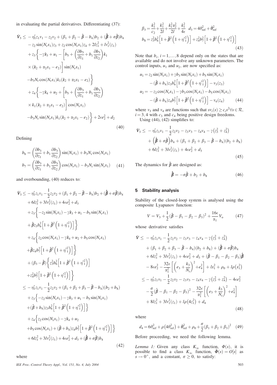
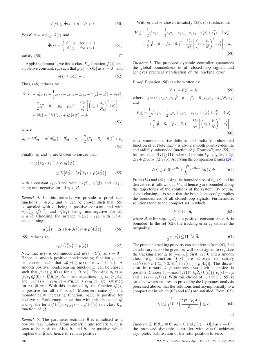
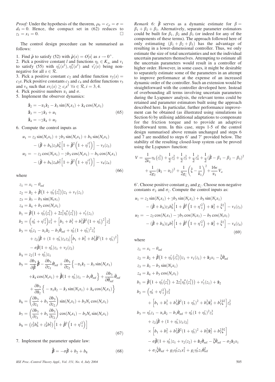
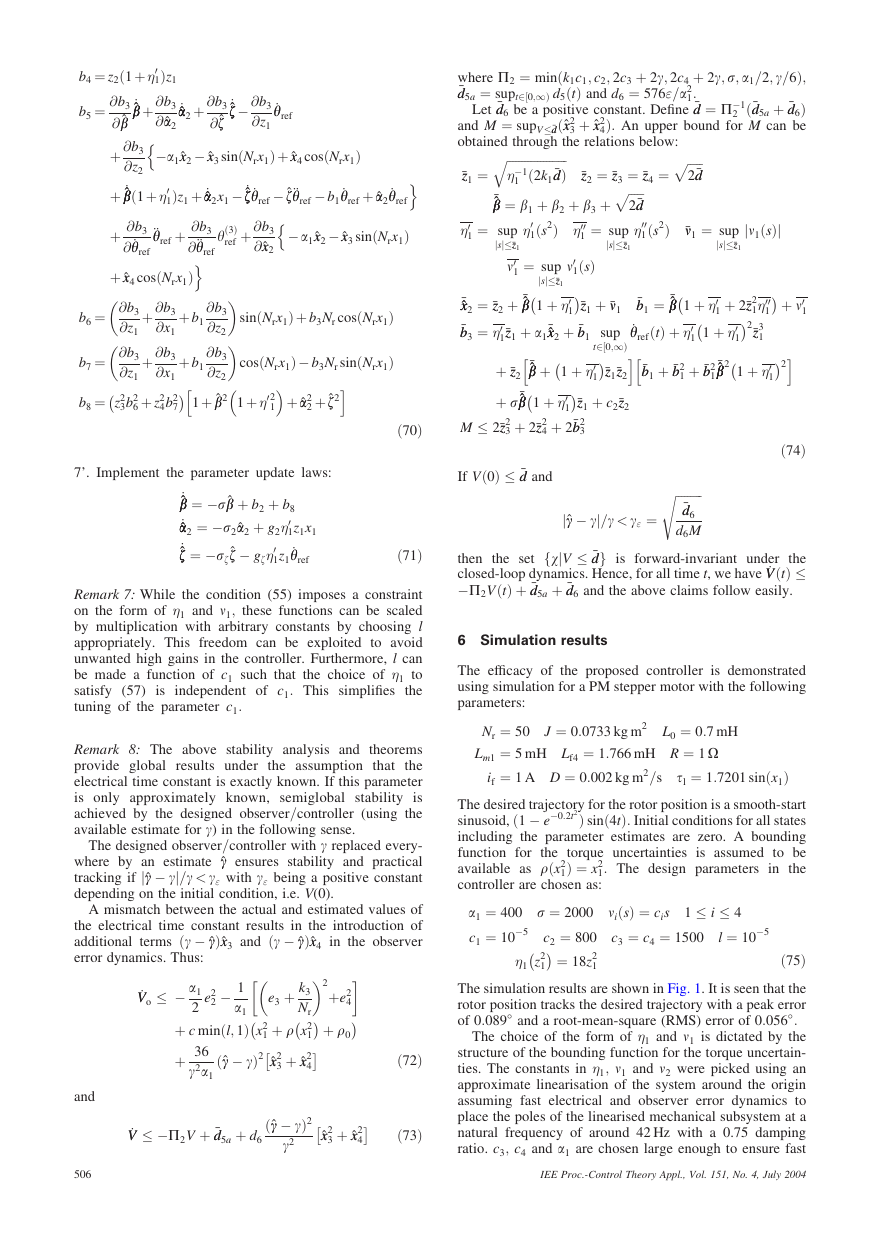
The simulation results are shown in Fig. 1. It is seen that the
rotor position tracks the desired trajectory with a peak error
of 0:089� and a root-mean-square (RMS) error of 0:056�:
The choice of the form of �1 and n1 is dictated by the
structure of the bounding function for the torque uncertain-
ties. The constants in �1; n1 and n2 were picked using an
approximate linearisation of the system around the origin
assuming fast electrical and observer error dynamics to
place the poles of the linearised mechanical subsystem at a
natural frequency of around 42 Hz with a 0.75 damping
ratio. c3; c4 and a1 are chosen large enough to ensure fast
IEE Proc.-Control Theory Appl., Vol. 151, No. 4, July 2004
�


 2023年江西萍乡中考道德与法治真题及答案.doc
 2012年重庆南川中考生物真题及答案.doc
 2013年江西师范大学地理学综合及文艺理论基础考研真题.doc
 2020年四川甘孜小升初语文真题及答案I卷.doc
 2020年注册岩土工程师专业基础考试真题及答案.doc
 2023-2024学年福建省厦门市九年级上学期数学月考试题及答案.doc
 2021-2022学年辽宁省沈阳市大东区九年级上学期语文期末试题及答案.doc
 2022-2023学年北京东城区初三第一学期物理期末试卷及答案.doc
 2018上半年江西教师资格初中地理学科知识与教学能力真题及答案.doc
 2012年河北国家公务员申论考试真题及答案-省级.doc
 2020-2021学年江苏省扬州市江都区邵樊片九年级上学期数学第一次质量检测试题及答案.doc
 2022下半年黑龙江教师资格证中学综合素质真题及答案.doc