ILI9163C
a-Si TFT LCD Single Chip Driver
132RGBx162 Resolution and 262K color
Specification
Version: V0.10
Document No.: ILI9163C_DS_V010.pdf
ILI TECHNOLOGY CORP.
8F, No.38, Taiyuan St., Jhubei City, Hsinchu County,
Taiwan 302, R.O.C.
Tel.886-3-5600099; Fax.886-3-5600585
http://www.ilitek.com
�
a-Si TFT LCD Single Chip Driver
132RGBx162 Resolution and 262K color
ILI9163C
1.
2.
3.
4.
5.
6.
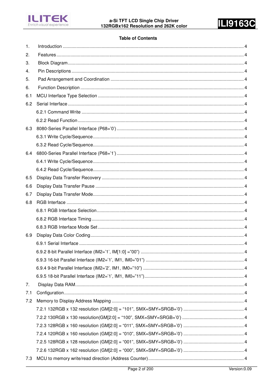
Table of Contents
Introduction ................................................................................................................................................ 4
Features ..................................................................................................................................................... 4
Block Diagram............................................................................................................................................ 4
Pin Descriptions ......................................................................................................................................... 4
Pad Arrangement and Coordination .......................................................................................................... 4
Function Description .................................................................................................................................. 4
6.1 MCU Interface Type Selection .................................................................................................................... 4
6.2 Serial Interface ............................................................................................................................................ 4
6.2.1 Command Write ................................................................................................................................. 4
6.2.2 Read Function .................................................................................................................................... 4
6.3 8080-Series Parallel Interface (P68=’0’) ..................................................................................................... 4
6.3.1 Write Cycle/Sequence........................................................................................................................ 4
6.3.2 Read Cycle/Sequence........................................................................................................................ 4
6.4 6800-Series Parallel Interface (P68=’1’) ..................................................................................................... 4
6.4.1 Write Cycle/Sequence........................................................................................................................ 4
6.4.2 Read Cycle/Sequence........................................................................................................................ 4
6.5 Display Data Transfer Recovery ................................................................................................................. 4
6.6 Display Data Transfer Pause ...................................................................................................................... 4
6.7 Display Data Transfer Mode........................................................................................................................ 4
6.8 RGB Interface ............................................................................................................................................. 4
6.8.1 RGB Interface Selection..................................................................................................................... 4
6.8.2 RGB Interface Timing ......................................................................................................................... 4
6.8.3 RGB Interface Mode Set .................................................................................................................... 4
6.9 Display Data Color Coding.......................................................................................................................... 4
6.9.1 Serial Interface ................................................................................................................................... 4
6.9.2 8-bit Parallel Interface (IM2=’1’, IM[1:0] =”00”) .................................................................................. 4
6.9.3 16-bit Parallel Interface (IM2=’1’, IM1, IM0=”01”) .............................................................................. 4
6.9.4 9-bit Parallel Interface (IM2=’2’, IM1, IM0=”10”) ................................................................................ 4
6.9.5 18-bit Parallel Interface (IM2=’1’, IM1, IM0=”11”)............................................................................... 4
7.
Display Data RAM...................................................................................................................................... 4
7.1 Configuration............................................................................................................................................... 4
7.2 Memory to Display Address Mapping ......................................................................................................... 4
7.2.1 132RGB x 132 resolution (GM[2:0] = “101”, SMX=SMY=SRGB=’0’) ................................................ 4
7.2.2 130RGB x 130 resolution(GM[2:0] = “100”, SMX=SMY=SRGB=’0’) ................................................. 4
7.2.3 128RGB x 160 resolution (GM[2:0] = “011”, SMX=SMY=SRGB=’0’) ................................................ 4
7.2.4 120RGB x 160 resolution (GM[2:0] = “010”, SMX=SMY=SRGB=’0’) ................................................ 4
7.2.5 128RGB x 128 resolution (GM[2:0] = “001”, SMX=SMY=SRGB=’0’) ................................................ 4
7.2.6 132RGB x 162 resolution (GM[2:0] = “000”, SMX=SMY=SRGB=’0’) ................................................ 4
7.3 MCU to memory write/read direction (Address Counter)............................................................................ 4
Page 2 of 200
Version:0.09
�
a-Si TFT LCD Single Chip Driver
132RGBx162 Resolution and 262K color
ILI9163C
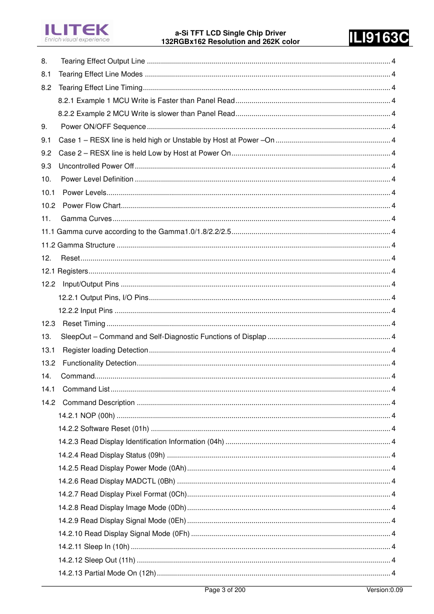
8.
Tearing Effect Output Line ......................................................................................................................... 4
8.1 Tearing Effect Line Modes .......................................................................................................................... 4
8.2 Tearing Effect Line Timing........................................................................................................................... 4
8.2.1 Example 1 MCU Write is Faster than Panel Read............................................................................. 4
8.2.2 Example 2 MCU Write is slower than Panel Read............................................................................. 4
9.
Power ON/OFF Sequence ......................................................................................................................... 4
9.1 Case 1 – RESX line is held high or Unstable by Host at Power –On ......................................................... 4
9.2 Case 2 – RESX line is held Low by Host at Power On............................................................................... 4
9.3 Uncontrolled Power Off ............................................................................................................................... 4
10. Power Level Definition ............................................................................................................................... 4
10.1 Power Levels............................................................................................................................................. 4
10.2 Power Flow Chart...................................................................................................................................... 4
11. Gamma Curves .......................................................................................................................................... 4
11.1 Gamma curve according to the Gamma1.0/1.8/2.2/2.5............................................................................... 4
11.2 Gamma Structure ........................................................................................................................................ 4
12. Reset.......................................................................................................................................................... 4
12.1 Registers...................................................................................................................................................... 4
12.2 Input/Output Pins ...................................................................................................................................... 4
12.2.1 Output Pins, I/O Pins........................................................................................................................ 4
12.2.2 Input Pins ......................................................................................................................................... 4
12.3 Reset Timing ............................................................................................................................................. 4
13. SleepOut – Command and Self-Diagnostic Functions of Displap ............................................................. 4
13.1 Register loading Detection........................................................................................................................ 4
13.2 Functionality Detection.............................................................................................................................. 4
14. Command................................................................................................................................................... 4
14.1 Command List ........................................................................................................................................... 4
14.2 Command Description .............................................................................................................................. 4
14.2.1 NOP (00h) ........................................................................................................................................ 4
14.2.2 Software Reset (01h) ....................................................................................................................... 4
14.2.3 Read Display Identification Information (04h) .................................................................................. 4
14.2.4 Read Display Status (09h) ............................................................................................................... 4
14.2.5 Read Display Power Mode (0Ah)..................................................................................................... 4
14.2.6 Read Display MADCTL (0Bh) .......................................................................................................... 4
14.2.7 Read Display Pixel Format (0Ch)..................................................................................................... 4
14.2.8 Read Display Image Mode (0Dh)..................................................................................................... 4
14.2.9 Read Display Signal Mode (0Eh) ..................................................................................................... 4
14.2.10 Read Display Signal Mode (0Fh) ................................................................................................... 4
14.2.11 Sleep In (10h) ................................................................................................................................. 4
14.2.12 Sleep Out (11h) .............................................................................................................................. 4
14.2.13 Partial Mode On (12h).................................................................................................................... 4
Page 3 of 200
Version:0.09
�
a-Si TFT LCD Single Chip Driver
132RGBx162 Resolution and 262K color
ILI9163C
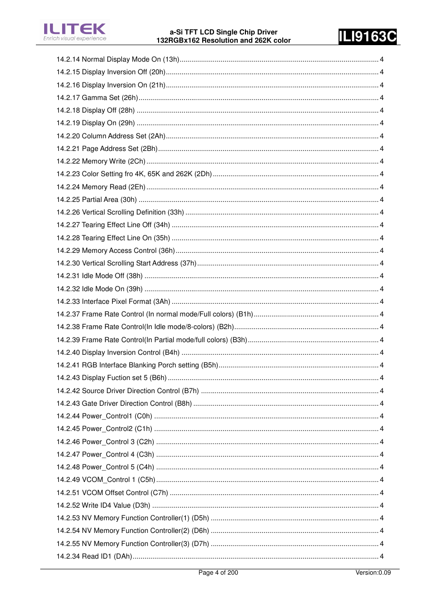
14.2.14 Normal Display Mode On (13h)...................................................................................................... 4
14.2.15 Display Inversion Off (20h)............................................................................................................. 4
14.2.16 Display Inversion On (21h)............................................................................................................. 4
14.2.17 Gamma Set (26h)........................................................................................................................... 4
14.2.18 Display Off (28h) ............................................................................................................................ 4
14.2.19 Display On (29h) ............................................................................................................................ 4
14.2.20 Column Address Set (2Ah)............................................................................................................. 4
14.2.21 Page Address Set (2Bh)................................................................................................................. 4
14.2.22 Memory Write (2Ch) ....................................................................................................................... 4
14.2.23 Color Setting fro 4K, 65K and 262K (2Dh)..................................................................................... 4
14.2.24 Memory Read (2Eh) ....................................................................................................................... 4
14.2.25 Partial Area (30h) ........................................................................................................................... 4
14.2.26 Vertical Scrolling Definition (33h) ................................................................................................... 4
14.2.27 Tearing Effect Line Off (34h) .......................................................................................................... 4
14.2.28 Tearing Effect Line On (35h) .......................................................................................................... 4
14.2.29 Memory Access Control (36h)........................................................................................................ 4
14.2.30 Vertical Scrolling Start Address (37h)............................................................................................. 4
14.2.31 Idle Mode Off (38h) ........................................................................................................................ 4
14.2.32 Idle Mode On (39h) ........................................................................................................................ 4
14.2.33 Interface Pixel Format (3Ah) .......................................................................................................... 4
14.2.37 Frame Rate Control (In normal mode/Full colors) (B1h)................................................................ 4
14.2.38 Frame Rate Control(In Idle mode/8-colors) (B2h).......................................................................... 4
14.2.39 Frame Rate Control(In Partial mode/full colors) (B3h)................................................................... 4
14.2.40 Display Inversion Control (B4h) ..................................................................................................... 4
14.2.41 RGB Interface Blanking Porch setting (B5h).................................................................................. 4
14.2.43 Display Fuction set 5 (B6h) ............................................................................................................ 4
14.2.42 Source Driver Direction Control (B7h) ........................................................................................... 4
14.2.43 Gate Driver Direction Control (B8h) ............................................................................................... 4
14.2.44 Power_Control1 (C0h) ................................................................................................................... 4
14.2.45 Power_Control2 (C1h) ................................................................................................................... 4
14.2.46 Power_Control 3 (C2h) .................................................................................................................. 4
14.2.47 Power_Control 4 (C3h) .................................................................................................................. 4
14.2.48 Power_Control 5 (C4h) .................................................................................................................. 4
14.2.49 VCOM_Control 1 (C5h).................................................................................................................. 4
14.2.51 VCOM Offset Control (C7h) ........................................................................................................... 4
14.2.52 Write ID4 Value (D3h) .................................................................................................................... 4
14.2.53 NV Memory Function Controller(1) (D5h) ...................................................................................... 4
14.2.54 NV Memory Function Controller(2) (D6h) ...................................................................................... 4
14.2.55 NV Memory Function Controller(3) (D7h) ...................................................................................... 4
14.2.34 Read ID1 (DAh).............................................................................................................................. 4
Page 4 of 200
Version:0.09
�
a-Si TFT LCD Single Chip Driver
132RGBx162 Resolution and 262K color
ILI9163C
14.2.35 Read ID2 (DBh).............................................................................................................................. 4
14.2.36 Read ID3 (DCh).............................................................................................................................. 4
14.2.56 Positive Gamma Correction Setting (E0h) ..................................................................................... 4
14.2.57 Negative Gamma Correction Setting (E1h) ................................................................................... 4
14.2.58 GAM_R_SEL (F2h) ........................................................................................................................ 4
15. Example Connection with Panel direction and Different Resolution.......................................................... 4
15.1 Application of connect with panel direction (when GM=’011’) .................................................................. 4
15.2 Application of connection with Different resolution ................................................................................... 4
16. OTP Programming Flow ............................................................................................................................ 4
17. Electrical Characteristics............................................................................................................................ 4
17.1 Absolute Maximum Ratings ...................................................................................................................... 4
17.2 DC Characteristics .................................................................................................................................... 4
17.3 AC Characteristics .................................................................................................................................... 4
17.3.1. Parallel CPU 18/16/9/8-bit Bus ....................................................................................................... 4
17.3.2. Display Serial Interface (SPI) .......................................................................................................... 4
17.3.2.1 3-pin Serial Interface .................................................................................................................. 4
17.3.2.2 4-pin Serial Interface .................................................................................................................. 4
17.3.3. Parallel RGB 18/16/6-bit Bus .......................................................................................................... 4
18. Revision History ......................................................................................................................................... 4
Page 5 of 200
Version:0.09
�
1. Introduction
a-Si TFT LCD Single Chip Driver
132RGBx162 Resolution and 262K color
ILI9163C
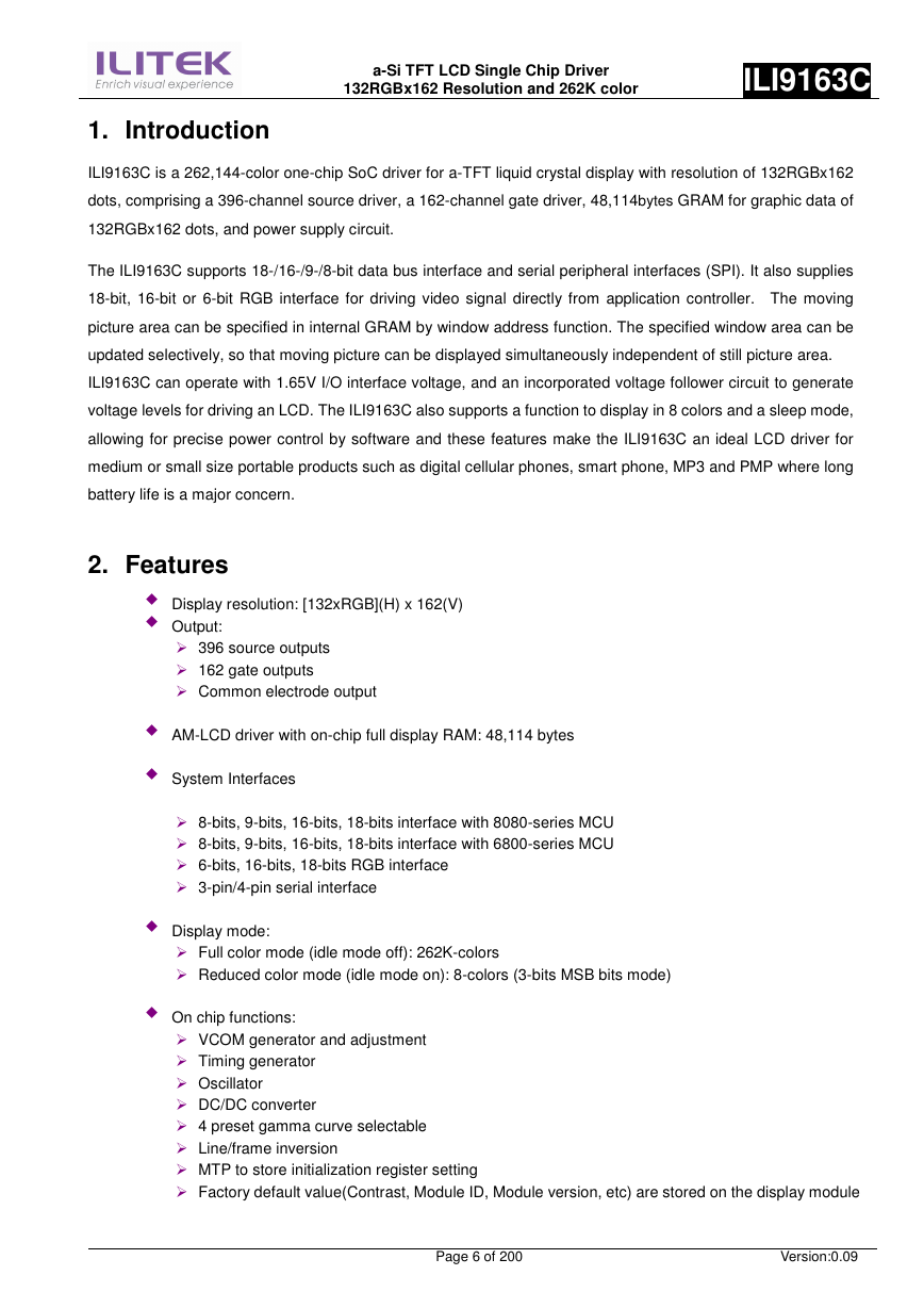
ILI9163C is a 262,144-color one-chip SoC driver for a-TFT liquid crystal display with resolution of 132RGBx162
dots, comprising a 396-channel source driver, a 162-channel gate driver, 48,114bytes GRAM for graphic data of
132RGBx162 dots, and power supply circuit.
The ILI9163C supports 18-/16-/9-/8-bit data bus interface and serial peripheral interfaces (SPI). It also supplies
18-bit, 16-bit or 6-bit RGB interface for driving video signal directly from application controller. The moving
picture area can be specified in internal GRAM by window address function. The specified window area can be
updated selectively, so that moving picture can be displayed simultaneously independent of still picture area.
ILI9163C can operate with 1.65V I/O interface voltage, and an incorporated voltage follower circuit to generate
voltage levels for driving an LCD. The ILI9163C also supports a function to display in 8 colors and a sleep mode,
allowing for precise power control by software and these features make the ILI9163C an ideal LCD driver for
medium or small size portable products such as digital cellular phones, smart phone, MP3 and PMP where long
battery life is a major concern.
2. Features
Display resolution: [132xRGB](H) x 162(V)
Output:
396 source outputs
162 gate outputs
Common electrode output
AM-LCD driver with on-chip full display RAM: 48,114 bytes
System Interfaces
8-bits, 9-bits, 16-bits, 18-bits interface with 8080-series MCU
8-bits, 9-bits, 16-bits, 18-bits interface with 6800-series MCU
6-bits, 16-bits, 18-bits RGB interface
3-pin/4-pin serial interface
Display mode:
Full color mode (idle mode off): 262K-colors
Reduced color mode (idle mode on): 8-colors (3-bits MSB bits mode)
On chip functions:
VCOM generator and adjustment
Timing generator
Oscillator
DC/DC converter
4 preset gamma curve selectable
Line/frame inversion
MTP to store initialization register setting
Factory default value(Contrast, Module ID, Module version, etc) are stored on the display module
Page 6 of 200
Version:0.09
�
MTP:
a-Si TFT LCD Single Chip Driver
132RGBx162 Resolution and 262K color
ILI9163C
8-bits for ID2
8-bits for ID3
7-bits for VCOM adjustment
Low –power consumption architecture
Low operating power supplies:
VDDI = 1.65V ~ 3.3 V (interface I/O)
VCI = 2.5V ~ 4.0 V (analog)
LCD Voltage drive:
Source/VCOM power supply voltage
AVDD – GND = 4.5V ~ 6.0V
VCL – GND = -1.0V ~ -3.0V
VCI1 – VCL
6.0V
Gate driver output voltage
VGH – GND = 10V ~ 16V
VGL – GND = -6V ~ -12V
VGH – VGL
30V
VCOM driver output voltage
VCOMH = 2.5V ~5V
VCOML = -2.5V ~ 0V
VCOMH-VCOML
6.0V
Operate temperature range: -40 to 85
Page 7 of 200
Version:0.09
�
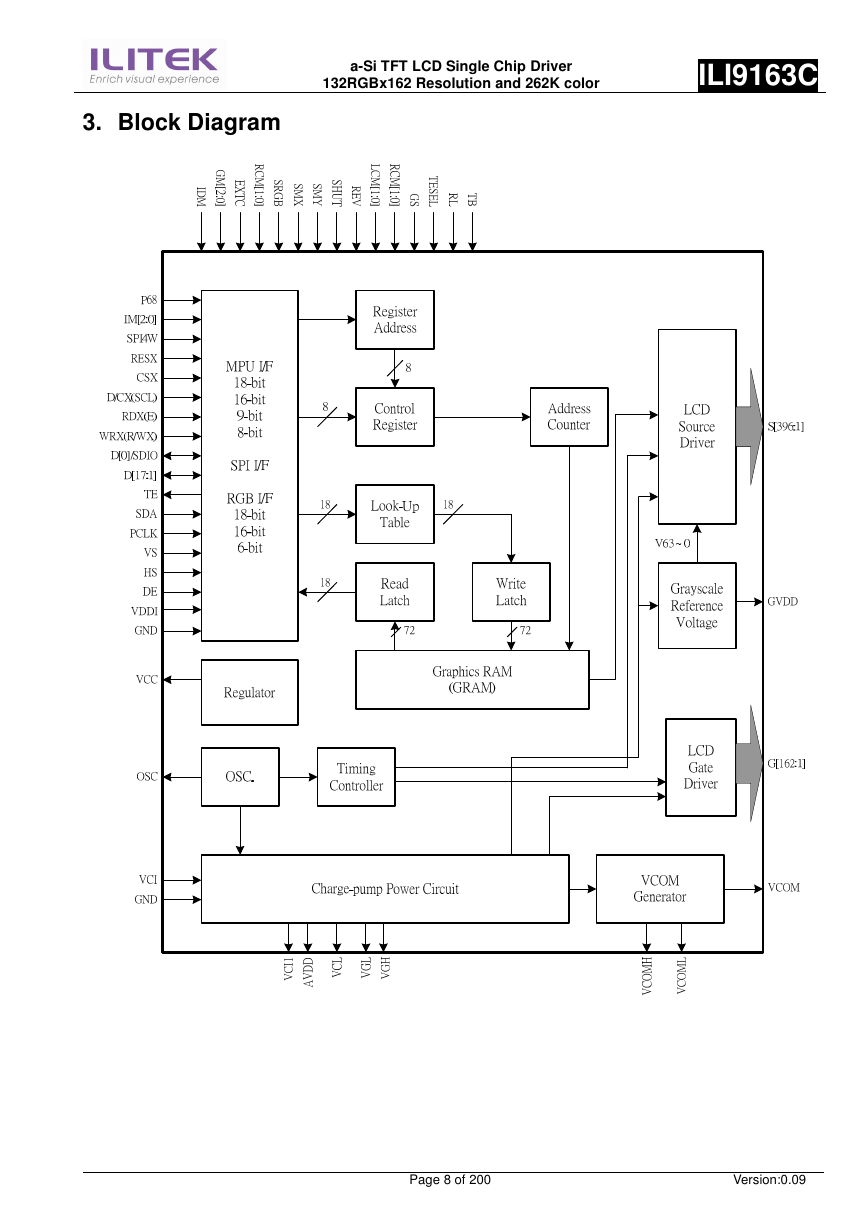
3. Block Diagram
a-Si TFT LCD Single Chip Driver
132RGBx162 Resolution and 262K color
ILI9163C
Page 8 of 200
Version:0.09
�


 2023年江西萍乡中考道德与法治真题及答案.doc
 2012年重庆南川中考生物真题及答案.doc
 2013年江西师范大学地理学综合及文艺理论基础考研真题.doc
 2020年四川甘孜小升初语文真题及答案I卷.doc
 2020年注册岩土工程师专业基础考试真题及答案.doc
 2023-2024学年福建省厦门市九年级上学期数学月考试题及答案.doc
 2021-2022学年辽宁省沈阳市大东区九年级上学期语文期末试题及答案.doc
 2022-2023学年北京东城区初三第一学期物理期末试卷及答案.doc
 2018上半年江西教师资格初中地理学科知识与教学能力真题及答案.doc
 2012年河北国家公务员申论考试真题及答案-省级.doc
 2020-2021学年江苏省扬州市江都区邵樊片九年级上学期数学第一次质量检测试题及答案.doc
 2022下半年黑龙江教师资格证中学综合素质真题及答案.doc