( DOC No. HX8368-A-DS )
HX8368-A (N)
320RGB x 240 dot, 262K color,
with internal GRAM,
TFT Mobile Single Chip Driver
Preliminary version 01 February, 2009
For Tianma_sz Only�
February, 2009
4.
5.
2.1
2.2
2.3
2.4
2.5
3.1
3.2
3.3
3.4
3.5
3.6
4.1
HX8368-A (N)
320RGB x 240 dot, 262K color, with internal
GRAM, TFT Mobile Single Chip Driver
List of Contents
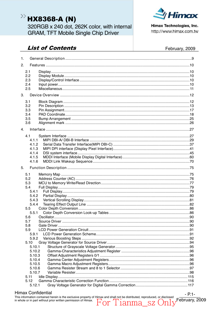
1. General Description............................................................................................................................9
2.
Features .............................................................................................................................................10
Display........................................................................................................................................10
Display Module...........................................................................................................................10
Display/Control Interface ............................................................................................................10
Input power.................................................................................................................................10
Miscellaneous.............................................................................................................................11
3. Device Overview ...............................................................................................................................12
Block Diagram ............................................................................................................................12
Pin Description ...........................................................................................................................13
Pin Assignment...........................................................................................................................17
PAD Coordinate..........................................................................................................................18
Bump Arrangement ....................................................................................................................25
Alignment mark ..........................................................................................................................26
Interface .............................................................................................................................................27
System Interface ........................................................................................................................27
4.1.1 MIPI DBI-A/ DBI-B Interface ..................................................................................................29
4.1.2 Serial Data Transfer Interface(MIPI DBI-C) ...........................................................................37
4.1.3 MIPI DPI interface (Display Pixel Interface)...........................................................................41
4.1.4 DSI system interface..............................................................................................................45
4.1.5 MDDI Interface (Mobile Display Digital Interface)..................................................................60
4.1.6 MDDI Link Wakeup Sequence...............................................................................................70
Function Description ........................................................................................................................75
Memory Map ..............................................................................................................................75
Address Counter (AC) ................................................................................................................76
MCU to Memory Write/Read Direction.......................................................................................77
Full Display.................................................................................................................................79
5.4.1 Full Display.............................................................................................................................79
5.4.2 Partial Display ........................................................................................................................80
5.4.3 Vertical Scrolling Display........................................................................................................81
5.4.4 Tearing Effect Output Line .....................................................................................................82
Color Depth Conversion .............................................................................................................86
5.5.1 Color Depth Conversion Look-up Tables ...............................................................................86
Oscillator.....................................................................................................................................90
Source Driver .............................................................................................................................90
Gate Driver .................................................................................................................................90
LCD Power Generation Circuit...................................................................................................91
5.9.1 LCD Power Generation Scheme............................................................................................91
5.9.2 Various Boosting Steps ..........................................................................................................92
5.10 Gray Voltage Generator for Source Driver .................................................................................94
Structure of Grayscale Voltage Generator.........................................................................95
Gamma-Characteristics Adjustment Register ...................................................................96
Offset Adjustment Registers 0/1 ........................................................................................96
Gamma Center Adjustment Registers...............................................................................96
Gamma Macro Adjustment Registers................................................................................96
Gamma Resister Stream and 8 to 1 Selector....................................................................97
Variable Resister................................................................................................................98
5.11
Idle Display...............................................................................................................................115
5.12 Gamma Characteristic Correction Function .............................................................................116
Gray Voltage Generator for Digital Gamma Correction...................................................117
5.10.1
5.10.2
5.10.3
5.10.4
5.10.5
5.10.6
5.10.7
5.5
5.6
5.7
5.8
5.9
5.1
5.2
5.3
5.4
5.12.1
Himax Confidential
This information contained herein is the exclusive property of Himax and shall not be distributed, reproduced, or disclosed
in whole or in part without prior written permission of Himax.
- P.1-
February, 2009
For Tianma_sz Only�
HX8368-A (N)
320RGB x 240 dot, 262K color, with internal
GRAM, TFT Mobile Single Chip Driver
List of Contents
5.13
5.14
February, 2009
5.15
5.17
5.18
5.17.1
5.17.2
5.17.3
5.18.1
5.18.2
5.14.1
5.14.2
5.15.1
5.15.2
5.20.1
5.20.2
5.20.3
5.20.4
5.16.1
5.16.2
5.16.3
5.16.4
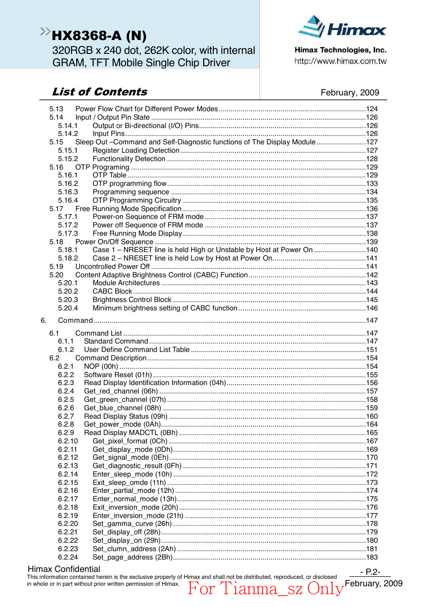
Power Flow Chart for Different Power Modes..........................................................................124
Input / Output Pin State ............................................................................................................126
Output or Bi-directional (I/O) Pins....................................................................................126
Input Pins.........................................................................................................................126
Sleep Out –Command and Self-Diagnostic functions of The Display Module.........................127
Register Loading Detection .............................................................................................127
Functionality Detection ....................................................................................................128
5.16 OTP Programing ......................................................................................................................129
OTP Table ........................................................................................................................129
OTP programming flow....................................................................................................133
Programming sequence ..................................................................................................134
OTP Programming Circuitry ............................................................................................135
Free Running Mode Specification ............................................................................................136
Power-on Sequence of FRM mode .................................................................................137
Power off Sequence of FRM mode .................................................................................137
Free Running Mode Display ............................................................................................138
Power On/Off Sequence ..........................................................................................................139
Case 1 – NRESET line is held High or Unstable by Host at Power On ..........................140
Case 2 – NRESET line is held Low by Host at Power On...............................................141
5.19 Uncontrolled Power Off ............................................................................................................141
5.20 Content Adaptive Brightness Control (CABC) Function...........................................................142
Module Architectures .......................................................................................................143
CABC Block .....................................................................................................................144
Brightness Control Block .................................................................................................145
Minimum brightness setting of CABC function ................................................................146
6. Command.........................................................................................................................................147
Command List ..........................................................................................................................147
6.1.1 Standard Command .............................................................................................................147
6.1.2 User Define Command List Table ........................................................................................151
Command Description..............................................................................................................154
6.2.1 NOP (00h) ............................................................................................................................154
6.2.2 Software Reset (01h) ...........................................................................................................155
6.2.3 Read Display Identification Information (04h)......................................................................156
6.2.4 Get_red_channel (06h) ........................................................................................................157
6.2.5 Get_green_channel (07h) ....................................................................................................158
6.2.6 Get_blue_channel (08h) ......................................................................................................159
6.2.7 Read Display Status (09h) ...................................................................................................160
6.2.8 Get_power_mode (0Ah).......................................................................................................164
6.2.9 Read Display MADCTL (0Bh) ..............................................................................................165
Get_pixel_format (0Ch) ...................................................................................................167
6.2.10
Get_display_mode (0Dh).................................................................................................169
6.2.11
6.2.12
Get_signal_mode (0Eh)...................................................................................................170
Get_diagnostic_result (0Fh) ............................................................................................171
6.2.13
Enter_sleep_mode (10h) .................................................................................................172
6.2.14
Exit_sleep_omde (11h) ....................................................................................................173
6.2.15
6.2.16
Enter_partial_mode (12h)................................................................................................174
Enter_normal_mode (13h)...............................................................................................175
6.2.17
Exit_inversion_mode (20h)..............................................................................................176
6.2.18
Enter_inversion_mode (21h) ...........................................................................................177
6.2.19
6.2.20
Set_gamma_curve (26h) .................................................................................................178
Set_display_off (28h).......................................................................................................179
6.2.21
Set_display_on (29h).......................................................................................................180
6.2.22
Set_clumn_address (2Ah) ...............................................................................................181
6.2.23
6.2.24
Set_page_address (2Bh).................................................................................................183
6.1
6.2
Himax Confidential
This information contained herein is the exclusive property of Himax and shall not be distributed, reproduced, or disclosed
in whole or in part without prior written permission of Himax.
- P.2-
February, 2009
For Tianma_sz Only�
February, 2009
HX8368-A (N)
320RGB x 240 dot, 262K color, with internal
GRAM, TFT Mobile Single Chip Driver
List of Contents
6.2.25 Write_memory_start (2Ch) ..............................................................................................185
6.2.26 Write_LUT (2Dh)..............................................................................................................186
Raed_memory_start (2Eh) ..............................................................................................187
6.2.27
6.2.28
Set_partial_area (30h) .....................................................................................................188
Set_scroll_area (33h) ......................................................................................................190
6.2.29
Tearing Effect Line Off (34h)............................................................................................193
6.2.30
Set_tear_on (35h)............................................................................................................194
6.2.31
6.2.32
Set_address_mode (36h) ................................................................................................195
Set_scroll_start (37h).......................................................................................................197
6.2.33
Idle Mode Off (38h)..........................................................................................................198
6.2.34
Enter_Idle_mode (39h)....................................................................................................199
6.2.35
6.2.36
Set_pixel_format (3Ah)....................................................................................................200
6.2.37 Write_memory_contiune (3Ch)........................................................................................201
Raed_memory_continue (3Eh)........................................................................................202
6.2.38
Set tear scan lines (44h)..................................................................................................203
6.2.39
6.2.40
Get Scan Lines (45h).......................................................................................................204
6.2.41 Write Display Brightness (51h) ........................................................................................205
6.2.42
Read Display Brightness Value (52h)..............................................................................206
6.2.43 Write CTRL Display (53h)................................................................................................207
6.2.44
Read CTRL Value Display (54h)......................................................................................208
6.2.45 Write Content Adaptive Brightness Control (55h)............................................................209
6.2.46
Read Content Adaptive Brightness Control (56h) ...........................................................210
6.2.47 Write CABC minimum brightness (5Eh) ..........................................................................211
Read CABC minimum brightness (5Fh) ..........................................................................212
6.2.48
6.2.49
Read Automatic Brightness Control Self-Diagnostic Result (68h) ..................................213
Read_DDB_start (A1h)....................................................................................................214
6.2.50
Read_DDB_continue (A8h) .............................................................................................216
6.2.51
Read ID1 (DAh) ...............................................................................................................217
6.2.52
Read ID2 (DBh) ...............................................................................................................218
6.2.53
6.2.54
Read ID3 (DCh) ...............................................................................................................219
SETOSC: Set Internal Oscillator (B0h)............................................................................220
6.2.55
SETPOWER: Set Power (B1h)........................................................................................221
6.2.56
SETDISP: Set Display Related Register (B2h) ...............................................................225
6.2.57
6.2.58
SETRGBIF: Set RGB Interface Related Register (B3h)..................................................228
SETCYC: Set Display Waveform Cycle (B4h).................................................................229
6.2.59
SETVCOM: Set VCOM Voltage (B6h).............................................................................232
6.2.60
SETEXTC: Set EXTC(B9) ...............................................................................................234
6.2.61
6.2.62
SETOTP: Set OTP Related Setting (BBh).......................................................................235
SETDGC (C1h)................................................................................................................236
6.2.63
SETID: Set ID (C3h) ........................................................................................................237
6.2.64
SETCABC(C9h)...............................................................................................................238
6.2.65
SECABCG: Set CABC Gain (CAh)..................................................................................240
6.2.66
6.2.67
SETPANEL (CCh)............................................................................................................242
SETCABCLUT: set CABCLUT related setting (CEh) ......................................................243
6.2.68
SETGAMMA: set gamma curve (E0h).............................................................................245
6.2.69
OTP_KEY[7:0] (E9h) .......................................................................................................246
6.2.70
6.2.71
CON_WR (FCh)...............................................................................................................247
CON_RD (FDh) ...............................................................................................................248
6.2.72
SET SPI RD (FEh)...........................................................................................................249
6.2.73
6.2.74
GET SPI RD (FFh)...........................................................................................................250
Layout Recommendation ...............................................................................................................251
Maximum layout resistance......................................................................................................252
External Components Connection ...........................................................................................253
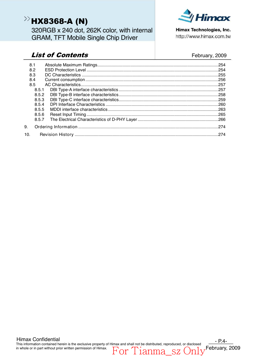
8. Electrical Characteristics ...............................................................................................................254
- P.3-
7.
7.1
7.2
Himax Confidential
This information contained herein is the exclusive property of Himax and shall not be distributed, reproduced, or disclosed
in whole or in part without prior written permission of Himax.
February, 2009
For Tianma_sz Only�
February, 2009
HX8368-A (N)
320RGB x 240 dot, 262K color, with internal
GRAM, TFT Mobile Single Chip Driver
List of Contents
8.1
8.2
8.3
8.4
8.5
Absolute Maximum Ratings......................................................................................................254
ESD Protection Level ...............................................................................................................254
DC Characteristics ...................................................................................................................255
Current consumption ................................................................................................................256
AC Characteristics....................................................................................................................257
8.5.1 DBI Type-A interface characteristics ....................................................................................257
8.5.2 DBI Type-B interface characteristics....................................................................................258
8.5.3 DBI Type-C interface characteristics....................................................................................259
8.5.4 DPI Interface Characteristics ...............................................................................................260
8.5.5 MDDI interface characteristics.............................................................................................263
8.5.6 Reset Input Timing ...............................................................................................................265
8.5.7 The Electrical Characteristics of D-PHY Layer ....................................................................266
9. Ordering Information ......................................................................................................................274
10.
Revision History .........................................................................................................................274
Himax Confidential
This information contained herein is the exclusive property of Himax and shall not be distributed, reproduced, or disclosed
in whole or in part without prior written permission of Himax.
- P.4-
February, 2009
For Tianma_sz Only�
HX8368-A (N)
320RGB x 240 dot, 262K color, with internal
GRAM, TFT Mobile Single Chip Driver
List of Contents
February, 2009
Figure 4.1 DBI-A System interface protocol, write to register or GRAM....................................29
Figure 4.2 DBI-A System interface protocol, read from register or GRAM ................................29
Figure 4.3 DBI-B System interface protocol, write to register or GRAM....................................30
Figure 4.4 DBI-B System interface protocol, read from register or GRAM ................................30
Figure 4.5 Example of DBI-A- / DBI-B- System 18-Bit Parallel Bus Interface ...........................31
Figure 4.6 Input Data Bus and GRAM Data Mapping in 18-Bit Bus System Interface ..............31
Figure 4.7 Example of DBI-A- / DBI-B- System 16-bit bus Interface .........................................32
Figure 4.8 Write data for RGB 4-4-4 (4k colours) bits input in 16-bit parallel Interface .............32
Figure 4.9 Write data for RGB 5-6-5 (65k colours) bits input in 16-bit parallel Interface ...........33
Figure 4.10 Write data option1 for RGB 6-6-6 (262k colours) bits input in 16-bit parallel Interface
............................................................................................................................................33
Figure 4.11 Example of DBI-A- / DBI-B- System 9-bit bus Interface..........................................34
Figure 4.12 Write data for RGB 6-6-6-bits (262kcolours) input in 9-bit parallel Interface..........34
Figure 4.13 Example of DBI-A- / DBI-B- System 8-bit bus Interface.......................................35
Figure 4.14 Write data for RGB 4-4-4 bits (4k colours) input in 8-bit parallel Interface .............35
Figure 4.15 Write data for RGB 5-6-5 (65k colours) bits input in 8-bit parallel Interface ...........36
Figure 4.16 Write data for RGB 6-6-6-bits(262k colours) input in 8-bit parallel Interface..........36
Figure 4.17 Serial Data stream, write mode...............................................................................37
Figure 4.18 DBI Type C -- Serial Interface protocol 3 wire/4 wire, write mode ..........................38
Figure 4.19 Type C -- Serial Interface protocol 3 wire/4 wire read mode ..................................39
Figure 4.20 Display Module Data Transfer Recovery ................................................................40
Figure 4.21 PCLK cycle..............................................................................................................41
Figure 4.22 General Timing Diagram.........................................................................................42
Figure 4.23 DPI (320RGBx240) timing diagram ........................................................................42
Figure 4.24 16 bit/pixel 65k Color Order on the DPI I/F.............................................................43
Figure 4.25 18 bit/pixel --- 262k Color Order on the DPI I/F ......................................................44
Figure 4.26 DSI transmitter and Receiver interface...................................................................45
Figure 4.27 DSI transmitter and Receiver interface...................................................................46
Figure 4.28 Multiple HS Transmission packets ..........................................................................47
Figure 4.29 Structure of the Short packet ..................................................................................47
Figure 4.30 Structure of the Long packet...................................................................................48
Figure 4.31 The format of Data ID..............................................................................................48
Figure 4.32 show Short- / Long- packet transmission command sequence ..............................49
Figure 4.33 Physical Connection of MDDI Host and Client .......................................................60
Figure 4.34 MDDI Terminology...................................................................................................61
Figure 4.35 Example of Bi-Directional MDDI Communication ...................................................61
Figure 4.36 Data-STB Encoding ................................................................................................62
Figure 4.37 Data / STB Generation & Recovery Circuit.............................................................62
Figure 4.38 Differential Connection between Host and Client ...................................................63
Figure 4.39 MDDI Packet Structure ...........................................................................................64
Figure 4.40 Panel Read is faster than MPU Write .....................................................................67
Figure 4.41 Panel Read is slower than MPU Write....................................................................68
Figure 4.42 MDDI Transceiver / Receiver State in Hibernation .................................................69
Figure 4.43 Host-initiated Link Wakeup Sequence ....................................................................70
Figure 4.44 Client-initiated Link Wake-up Sequence .................................................................71
Figure 4.45 MDDI Operation Mode ............................................................................................74
Figure 5.1 MCU to Memory Write/Read Direction......................................................................77
Figure 5.2 MY, MX, MV Setting of 320RGB x 240 Dot ..............................................................77
Figure 5.3 Address Direction Settings........................................................................................78
Figure 5.4 320RGB x 240 Resolution ........................................................................................79
Figure 5.5 Memory map of partial display..................................................................................80
Figure 5.6 Vertical Scrolling........................................................................................................81
Figure 5.7 Memory Map of Vertical Scrolling .............................................................................81
Figure 5.8 Tearing Effect Output Line – Mode1 (320RGBx240 dot) ..........................................82
Figure 5.9 Tearing Effect Output Line – Mode2 .........................................................................82
Himax Confidential
This information contained herein is the exclusive property of Himax and shall not be distributed, reproduced, or disclosed
in whole or in part without prior written permission of Himax.
- P.5-
February, 2009
For Tianma_sz Only�
HX8368-A (N)
320RGB x 240 dot, 262K color, with internal
GRAM, TFT Mobile Single Chip Driver
List of Contents
February, 2009
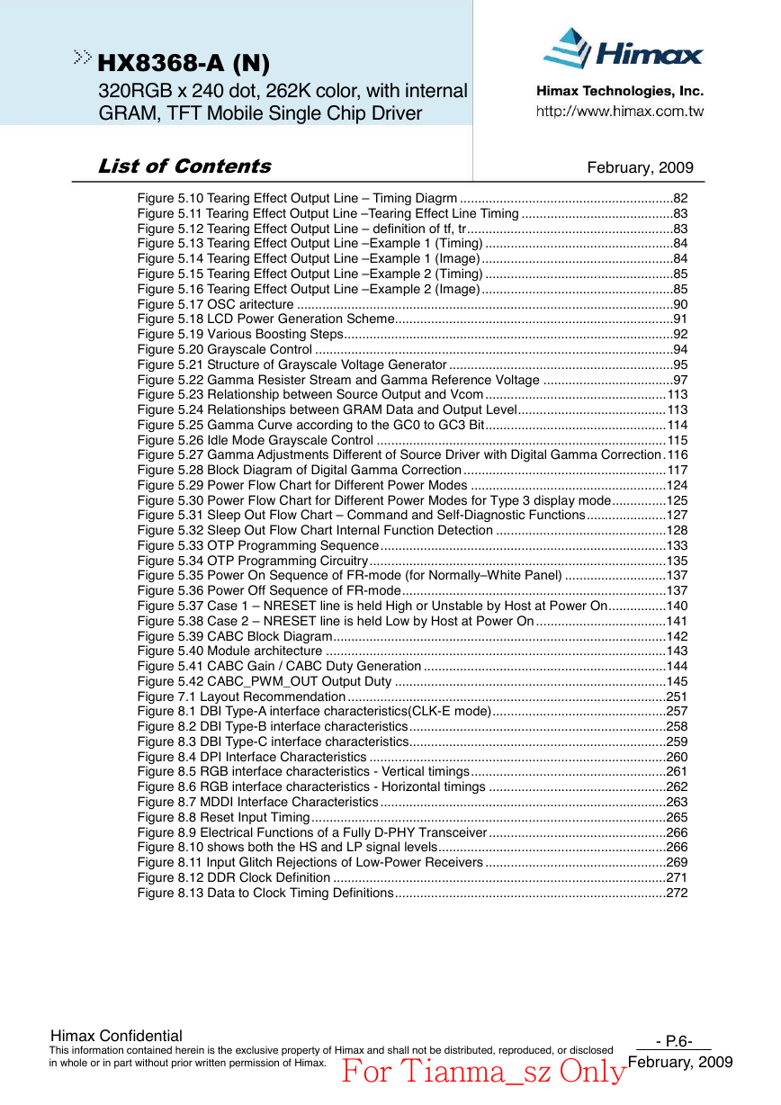
Figure 5.10 Tearing Effect Output Line – Timing Diagrm ...........................................................82
Figure 5.11 Tearing Effect Output Line –Tearing Effect Line Timing ..........................................83
Figure 5.12 Tearing Effect Output Line – definition of tf, tr.........................................................83
Figure 5.13 Tearing Effect Output Line –Example 1 (Timing) ....................................................84
Figure 5.14 Tearing Effect Output Line –Example 1 (Image).....................................................84
Figure 5.15 Tearing Effect Output Line –Example 2 (Timing) ....................................................85
Figure 5.16 Tearing Effect Output Line –Example 2 (Image).....................................................85
Figure 5.17 OSC aritecture ........................................................................................................90
Figure 5.18 LCD Power Generation Scheme.............................................................................91
Figure 5.19 Various Boosting Steps...........................................................................................92
Figure 5.20 Grayscale Control ...................................................................................................94
Figure 5.21 Structure of Grayscale Voltage Generator ..............................................................95
Figure 5.22 Gamma Resister Stream and Gamma Reference Voltage ....................................97
Figure 5.23 Relationship between Source Output and Vcom ..................................................113
Figure 5.24 Relationships between GRAM Data and Output Level.........................................113
Figure 5.25 Gamma Curve according to the GC0 to GC3 Bit..................................................114
Figure 5.26 Idle Mode Grayscale Control ................................................................................115
Figure 5.27 Gamma Adjustments Different of Source Driver with Digital Gamma Correction.116
Figure 5.28 Block Diagram of Digital Gamma Correction ........................................................117
Figure 5.29 Power Flow Chart for Different Power Modes ......................................................124
Figure 5.30 Power Flow Chart for Different Power Modes for Type 3 display mode...............125
Figure 5.31 Sleep Out Flow Chart – Command and Self-Diagnostic Functions......................127
Figure 5.32 Sleep Out Flow Chart Internal Function Detection ...............................................128
Figure 5.33 OTP Programming Sequence...............................................................................133
Figure 5.34 OTP Programming Circuitry..................................................................................135
Figure 5.35 Power On Sequence of FR-mode (for Normally–White Panel) ............................137
Figure 5.36 Power Off Sequence of FR-mode.........................................................................137
Figure 5.37 Case 1 – NRESET line is held High or Unstable by Host at Power On................140
Figure 5.38 Case 2 – NRESET line is held Low by Host at Power On ....................................141
Figure 5.39 CABC Block Diagram............................................................................................142
Figure 5.40 Module architecture ..............................................................................................143
Figure 5.41 CABC Gain / CABC Duty Generation ...................................................................144
Figure 5.42 CABC_PWM_OUT Output Duty ...........................................................................145
Figure 7.1 Layout Recommendation ........................................................................................251
Figure 8.1 DBI Type-A interface characteristics(CLK-E mode)................................................257
Figure 8.2 DBI Type-B interface characteristics.......................................................................258
Figure 8.3 DBI Type-C interface characteristics.......................................................................259
Figure 8.4 DPI Interface Characteristics ..................................................................................260
Figure 8.5 RGB interface characteristics - Vertical timings......................................................261
Figure 8.6 RGB interface characteristics - Horizontal timings .................................................262
Figure 8.7 MDDI Interface Characteristics ...............................................................................263
Figure 8.8 Reset Input Timing..................................................................................................265
Figure 8.9 Electrical Functions of a Fully D-PHY Transceiver .................................................266
Figure 8.10 shows both the HS and LP signal levels...............................................................266
Figure 8.11 Input Glitch Rejections of Low-Power Receivers ..................................................269
Figure 8.12 DDR Clock Definition ............................................................................................271
Figure 8.13 Data to Clock Timing Definitions...........................................................................272
Himax Confidential
This information contained herein is the exclusive property of Himax and shall not be distributed, reproduced, or disclosed
in whole or in part without prior written permission of Himax.
- P.6-
February, 2009
For Tianma_sz Only�
HX8368-A (N)
320RGB x 240 dot, 262K color, with internal
GRAM, TFT Mobile Single Chip Driver
List of Contents
February, 2009
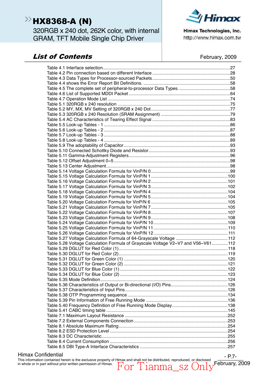
Table 4.1 Interface selection.......................................................................................................27
Table 4.2 Pin connection based on different Interface ...............................................................28
Table 4.3 Data Types for Processor-sourced Packets...............................................................50
Table 4.4 shows the Error Report Bit Definitions. ......................................................................58
Table 4.5 The complete set of peripheral-to-processor Data Types. .........................................58
Table 4.6 List of Supported MDDI Packet ..................................................................................64
Table 4.7 Operation Mode List ...................................................................................................74
Table 5.1 320RGB x 240 resolution ...........................................................................................75
Table 5.2 MY, MX, MV Setting of 320RGB x 240 Dot................................................................77
Table 5.3 320RGB x 240 Resolution (SRAM Assignment) ........................................................79
Table 5.4 AC Characteristics of Tearing Effect Signal ...............................................................83
Table 5.5 Look-up Tables - 1 ......................................................................................................86
Table 5.6 Look-up Tables - 2 ......................................................................................................87
Table 5.7 Look-up Tables - 3 ......................................................................................................88
Table 5.8 Look-up Tables - 4 ......................................................................................................89
Table 5.9 The adoptability of Capacitor......................................................................................93
Table 5.10 Connected Schottky Diode and Resistor..................................................................93
Table 5.11 Gamma-Adjustment Registers..................................................................................96
Table 5.12 Offset Adjustment 0~5 ..............................................................................................98
Table 5.13 Center Adjustment....................................................................................................98
Table 5.14 Voltage Calculation Formula for VinP/N 0................................................................99
Table 5.15 Voltage Calculation Formula for VinP/N 1..............................................................100
Table 5.16 Voltage Calculation Formula for VinP/N 2..............................................................101
Table 5.17 Voltage Calculation Formula for VinP/N 3..............................................................102
Table 5.18 Voltage Calculation Formula for VinP/N 4..............................................................104
Table 5.19 Voltage Calculation Formula for VinP/N 5..............................................................104
Table 5.20 Voltage Calculation Formula for VinP/N 6 ..............................................................105
Table 5.21 Voltage Calculation Formula for VinP/N 7..............................................................105
Table 5.22 Voltage Calculation Formula for VinP/N 8..............................................................107
Table 5.23 Voltage Calculation Formula for VinP/N 9..............................................................108
Table 5.24 Voltage Calculation Formula for VinP/N 10............................................................109
Table 5.25 Voltage Calculation Formula for VinP/N 11............................................................110
Table 5.26 Voltage Calculation Formula for VinP/N 12............................................................ 111
Table 5.27 Voltage Calculation Formula of 64-Grayscale Voltage ..........................................112
Table 5.28 Voltage Calculation Formula of Grayscale Voltage V2~V7 and V56~V61.............112
Table 5.29 DGLUT for Red Color (1)........................................................................................118
Table 5.30 DGLUT for Red Color (2)........................................................................................119
Table 5.31 DGLUT for Green Color (1) ....................................................................................120
Table 5.32 DGLUT for Green Color (2) ....................................................................................121
Table 5.33 DGLUT for Blue Color (1) .......................................................................................122
Table 5.34 DGLUT for Blue Color (2) .......................................................................................123
Table 5.35 Mode Definition.......................................................................................................124
Table 5.36 Characteristics of Output or Bi-directional (I/O) Pins..............................................126
Table 5.37 Characteristics of Input Pins...................................................................................126
Table 5.38 OTP Programming sequence .................................................................................134
Table 5.39 Pin Information of Free Running Mode ..................................................................136
Table 5.40 Frequency Definition of Free Running Mode Display.............................................138
Table 5.41 CABC timing table ..................................................................................................145
Table 7.1 Maximum Layout Resistance ...................................................................................252
Table 7.2 External Components Connection............................................................................253
Table 8.1 Absolute Maximum Rating........................................................................................254
Table 8.2 ESD Protection Level ...............................................................................................254
Table 8.3 DC Characteristic......................................................................................................255
Table 8.4 Current Consumption ...............................................................................................256
Table 8.5 DBI Type-A Interface Characteristics .......................................................................257
Himax Confidential
This information contained herein is the exclusive property of Himax and shall not be distributed, reproduced, or disclosed
in whole or in part without prior written permission of Himax.
- P.7-
February, 2009
For Tianma_sz Only�




 2023年江西萍乡中考道德与法治真题及答案.doc
 2012年重庆南川中考生物真题及答案.doc
 2013年江西师范大学地理学综合及文艺理论基础考研真题.doc
 2020年四川甘孜小升初语文真题及答案I卷.doc
 2020年注册岩土工程师专业基础考试真题及答案.doc
 2023-2024学年福建省厦门市九年级上学期数学月考试题及答案.doc
 2021-2022学年辽宁省沈阳市大东区九年级上学期语文期末试题及答案.doc
 2022-2023学年北京东城区初三第一学期物理期末试卷及答案.doc
 2018上半年江西教师资格初中地理学科知识与教学能力真题及答案.doc
 2012年河北国家公务员申论考试真题及答案-省级.doc
 2020-2021学年江苏省扬州市江都区邵樊片九年级上学期数学第一次质量检测试题及答案.doc
 2022下半年黑龙江教师资格证中学综合素质真题及答案.doc