Computers & Operations Research 40 (2013) 1729–1743
Contents lists available at SciVerse ScienceDirect
Computers & Operations Research
journal homepage: www.elsevier.com/locate/caor
A variable iterated greedy algorithm with differential evolution
for the no-idle permutation flowshop scheduling problem
M. Fatih Tasgetiren a,n, Quan-Ke Pan b, P.N. Suganthan c, Ozge Buyukdagli a
a Industrial Engineering Department, Yasar University, Izmir, Turkey
b College of Computer Science, Liaocheng University, Liaocheng, Shandong, PR China
c School of Electrical and Electronic Engineering, Nanyang Technological University, Singapore 639798, Singapore
a r t i c l e i n f o
a b s t r a c t
Available online 31 January 2013
Keywords:
Differential evolution algorithm
Iterated greedy algorithm
No-idle permutation flowshop
scheduling problem
Heuristic optimization.
This paper presents a variable iterated greedy algorithm (IG) with differential evolution (vIG_DE),
designed to solve the no-idle permutation flowshop scheduling problem. In an IG algorithm, size d of
jobs are removed from a sequence and re-inserted into all possible positions of the remaining
sequences of jobs, which affects the performance of the algorithm. The basic concept behind the
proposed vIG_DE algorithm is to employ differential evolution (DE) to determine two important
parameters for the IG algorithm, which are the destruction size and the probability of applying the IG
algorithm to an individual. While DE optimizes the destruction size and the probability on a continuous
domain by using DE mutation and crossover operators, these two parameters are used to generate a
trial individual by directly applying the IG algorithm to each target individual depending on the
probability. Next, the trial individual is replaced with the corresponding target individual if it is better
in terms of fitness. A unique multi-vector chromosome representation is presented in such a way that
the first vector represents the destruction size and the probability, which is a DE vector, whereas the
second vector simply consists of a job permutation assigned to each individual in the target population.
Furthermore, the traditional IG and a variable IG from the literature are re-implemented as well. The
proposed algorithms are applied to the no-idle permutation flowshop scheduling (NIPFS) problem with
the makespan and total flowtime criteria. The performances of the proposed algorithms are tested on
the Ruben Ruiz benchmark suite and compared to the best-known solutions available at http://soa.iti.
es/rruiz as well as to those from a recent discrete differential evolution algorithm (HDDE) from the
literature. The computational results show that all three IG variants represent state-of-art methods for
the NIPFS problem.
& 2013 Elsevier Ltd. All rights reserved.
1.
Introduction
The processing order is the same for all jobs in a flowshop
situation. Furthermore, the job sequences are assumed to be
permutations; therefore, once a permutation is fixed for all jobs
on the first machine, this permutation is maintained for all
machines, which is the so-called permutation flowshop schedul-
ing problem (PFSP). Although several performance measures exist
for scheduling in a flowshop, the makespan criterion is the most
commonly studied performance measure in the literature (see
[1,2] for recent reviews of this problem).
This study focuses on solving a variant of the PFSP in which
idle times are not allowed on machines. The no-idle constraint
n Corresponding author.
E-mail addresses: fatih.tasgetiren@yasar.edu.tr (M. Fatih Tasgetiren),
panquanke@gmail.com (Q.-K. Pan), epnsugan@ntu.edu.sg (P.N. Suganthan),
ozge.buyukdagli@yasar.edu.tr (O. Buyukdagli).
0305-0548/$ - see front matter & 2013 Elsevier Ltd. All rights reserved.
http://dx.doi.org/10.1016/j.cor.2013.01.005
refers to an important practical situation in the production
environment in which expensive machinery is employed [3],
and idling of such expensive machinery is often undesirable. For
instance, the steppers employed in the production of integrated
circuits via photolithography are clear examples. Certain other
examples arise in industries where less expensive machinery is
employed. However,
the machines cannot be stopped and
restarted. For example, ceramic roller kilns consume large quan-
tities of natural gas when in operation. Idling is not an option in
this case because it takes several days to stop and restart the kiln
due to notably large thermal inertia. In such cases, idling should
be avoided. Another practical example is the furnace used in
fiberglass processing in which glass batches are reduced to
molten glass. Because it takes three days to heat the furnace back
to the required temperature of 2800 1F, the furnace should remain
in operation during the entire production season. In addition to
the above examples, the three-machine flowshop production of
engine blocks in a foundry is presented in [4]. This example
�
1730
M Fatih Tasgetiren et al. / Computers & Operations Research 40 (2013) 1729–1743
includes the casting of sand molds and sand cores. The molds are
filled with metal in fusion, and the cores prevent the metal from
filling certain species in the mold. The casting machines operate
without idle times due to both economic and technological
constraints.
In a NIPFS problem, each machine must process jobs without any
interruption from the start of processing the first job to the
completion of the last job. Therefore, when needed, the start of
processing the first job on a given machine must be delayed to meet
the no-idle requirement. In this work, we denote the NIPFS problem
with the well-known three-fold notation of Fm=prmu,no�idle=Cmax.
The computational complexity of the Fm=prmu,no�idle=Cmax pro-
blem is briefly commented in [5]. The NP-Hardness of
the
F3=prmu,no�idle=Cmax problem was proven by [6,4]. Therefore, this
problem has a significant importance both in theory and engineer-
ing applications
for development of effective and efficient
approaches to the problem discussed in this paper.
P
Despite its practical importance, the Fm=prmu,no�idle=Cmax
problem has not attracted much attention in the literature [7].
A polynomial time algorithm for optimally solving the F2/prmu,
no_idle/
Cj problem was presented in [8]. The makespan criter-
ion was studied for the first time in [9], whereas heuristic
approaches for the general m-machine NIPFS problem with the
makespan criterion were examined in [10]. A branch-and-bound
(B&B) method is also presented by [6] for the general m-machine
NIPFS problem with the makespan criterion.
Certain mistakes in the paper by [8] were reported in [11]. The
F3=prmu,no�idle=Cmax problem was studied in [12], and the same
problem was also studied in [4], in which a lower bound and an
efficient heuristic are presented. This new heuristic favors the earlier
method of the authors [13], who published this work later on in [14].
Kamburowski in [15] further enhanced the idea in [4] by proposing a
network representation. A heuristic for the F3=prmu,no�idle=Cmax
problem based on the traveling salesman problem (TSP) was pro-
posed in [14]. The F2=prmu,no�idle=Cmax and Fm=prmu,no�
idle=Cmax problems were studied in two similar papers [12,16].
In [17], Kalczynski and Kamburowski developed a constructive
heuristic, called the KK heuristic, for the Fm=prmu,no�idle=Cmax
problem with a time complexity of O(n2m). The authors also
presented an adaptation of the Nawaz, Enscore and the Ham (NEH)
heuristic [18] for the NIPFS problem. In addition, Kalczynski and
Kamburowski studied the interactions between the no-idle and no-
wait flowshops in [17] as well. Recently, Baraz and Mosheiov
introduced an improved two-stage greedy algorithm named GH_BM,
which consists of a simple greedy heuristic and an improvement step
based on the adjacent pairwise interchange (API) method in [7].
In recent years, meta-heuristics have attracted increasing
attention in the solution of scheduling problems because they
are able to provide high quality solutions with reasonable
computational effort [19]. In addition to the above literature, in
two similar papers, Pan and Wang in [20,21] proposed discrete
differential evolution (DDE_LS) and a hybrid discrete particle
swarm optimization (HDPSO) algorithm for the same problem.
In both papers, a speed-up scheme for the insertion neighborhood
is proposed that reduces the computational complexity of a single
insertion neighborhood scan from O(n3m) to O(n2m) when the
insertion is carried out in order. The speed-up that they proposed
is based on the well-known accelerations presented by [22] for
the insertion neighborhood for the PFSP. In fact, both in DDE_LS
and HDPSO, an advanced local search form, an IG algorithm
proposed by [23], is employed as a local search. Both DDE_LS
and HDPSO used the well-known benchmark suite of [24] by
treating these as NIPFS instances to test the results. In both
papers, the authors tested the proposed methods against the
heuristics in [7,25]. Recently, an IG_LS algorithm for the NIPFS
problem with the makespan criterion was presented in [3]. These
Fig. 1. (a) Computation of FðpE
(c) Computation of FðpE
1,k,kþ1Þ,
3,k,kþ1Þ and (d) Computation of CmaxðpÞ.
(b) Computation of FðpE
2,k,kþ1Þ,
researchers employed their own benchmark suite and examined
the performance of IG_LS in detail against the existing heuristics
and meta-heuristics from the literature, whereas a continuous DE
algorithm is presented in [26]. Most recently, a hybrid discrete
differential evolution algorithm (HDDE) was presented in [27] in
which a speed-up method based on network representation is
proposed to evaluate the entire insertion neighborhood of a job
permutation. Through a detailed experimental campaign, it was
concluded that the HDDE algorithm was superior to the existing
state-of-the-art algorithms from the literature.
In this paper, a vIG_DE algorithm and two other IG variants are
presented for comparison to the best-known solutions in [3] as
well as solutions presented by the HDDE algorithm in [27]. The
computational results show that all three IG variants represent
state-of-art methods for the NIPFS problem.
The remaining part of the paper is organized as follows.
Section 2 introduces the NIPFS problem. Section 3 presents the
�
M Fatih Tasgetiren et al. / Computers & Operations Research 40 (2013) 1729–1743
1731
ð6Þ
ð7Þ
calculated as follows:
EðpF
n,k,kþ1Þ ¼ pðpn,kÞ
k ¼ 1,2,:::,m�1
EðpF
j ,k,kþ1Þ ¼ maxfEðpF
j ¼ n�1,n�2,:::,1 and k ¼ 1,2,::,m�1
jþ 1,k,kþ1Þ�pðpj,kþ1Þ,0gþpðpj,kÞ
The completion time C(p1,m) of job p1 on the last machine m
can be given as follows:
Cðp1,mÞ ¼
EðpF
1,k,kþ1Þþ pðp1,mÞ
ð8Þ
Then, the makespan of the job p1 can be given in an alternative
vIG_DE algorithm and two other IG variants in detail, and
Section 4 discusses the computational results in the context of
benchmark problems. Finally, Section 5 presents the concluding
remarks.
2. No-idle permutation flowshop scheduling problem
The NIPFS problem with n (j¼1,2,..,n) jobs and m (k¼1,2,..,m)
machines can be defined as follows. Each job will be sequenced
through m machines. p(j, k) denotes the processing time in which
the setup time is included. At any time, each machine can process
at most one job, and each job can be processed on at most one
machine. The sequence in which the jobs are to be processed is
the same for each machine. To follow the no-idle restriction, each
machine must process jobs without any interruption from the
start of processing the first job to the completion of processing of
the last job. The aim is then to find the same permutation on each
machine to minimize the makespan. We follow the approach of
Pan and Wang in [20,21] and elaborate the formulation of the
NIPFS problem with the makespan and total flowtime criteria. The
formulation consists of forward and backward passes as well as a
combined method to facilitate the speed-up, which will be
explained and illustrated with an example in Appendix A.
X
m�1
k ¼ 1
X
m�1
k ¼ 1
approach,
Cmaxðp1Þ ¼
X
n
j ¼ 1
Eðp1,k,kþ1Þþ
pðpj,mÞ
ð9Þ
Now, it is trivial to compute the completion time C(pjþ 1,m) of
job pjþ 1on the last machine m, which can be obtained as follows:
ð10Þ
Cðpjþ 1,mÞ ¼ Cðpj,mÞþpðpjþ 1,mÞ,
j ¼ 1,2,. . .,n�1
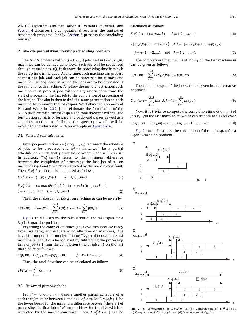
Fig. 2a to d illustrates the calculation of the makespan for a
2.1. Forward pass calculation
3-job 3-machine problem.
Let a job permutation p¼{p1,p2,y,pn} represent the schedule
j ¼ fp1,p2,. . .,pjg be a partial
jobs to be processed and pE
of
schedule of p such that j must be between 1 and n (1ojon).
In addition, FðpE
j ,k,kþ1Þ refers to the minimum difference
between the completion of processing the last job of pE
j on
machines kþ1 and k, which is restricted by the no-idle constraint.
Then, FðpE
FðpE
FðpE
j ¼ 2,3,::,n and k ¼ 1,2,::,m�1
1,k,kþ1Þ ¼ pðp1,kþ1Þ
j ,k,kþ1Þ ¼ maxfFðpE
ð2Þ
Then, the makespan of job pn on machine m can be given by
j ,k,kþ1Þ can be computed as follows:
j�1,k,kþ1Þ�pðpj,kÞ,0gþ pðpj,kþ1Þ
k ¼ 1,2,:::,m�1
ð1Þ
Cðpn,mÞ ¼ CmaxðpE
nÞ ¼
FðpE
n,k,kþ1Þþ
pðpj,1Þ
ð3Þ
X
m�1
k ¼ 1
X
n
j ¼ 1
Fig. 1a to d illustrates the calculation of the makespan for a
3-job 3-machine problem.
Regarding the completion times (i.e., flowtimes because ready
times are zero), as the there is no idle time on machines, it is
trivial to compute the completion time C(pj,m) of job pj on the last
machine m, and it can be achieved by subtracting the processing
time of job jþ1 from the completion time of job jþ1 on the last
machine m as follows:
Cðpj,mÞ ¼ Cðpjþ 1,mÞ�pðpjþ 1,mÞ
j ¼ n�1,n�2,::,1
ð4Þ
Thus, the total flowtime can be calculated as follows:
TFTðpÞ ¼
Cðpj,mÞ
ð5Þ
X
n
j ¼ 1
2.2. Backward pass calculation
Let pF
j ¼ fpj,pjþ 1,:::,png denote another partial schedule of p
such that j must be between 1 and n (1ojon). Let EðpF
j ,k,kþ1Þ be
the lower bound for the minimum difference between the start of
processing the first job of pF on machines kþ1 and k, which is
restricted by the no-idle constraint. Then, EðpF
j ,k,kþ1Þ can be
Fig. 2. (a) Computation of EðpF
(c) Computation of EðpF
3,k,kþ1Þ,
(b) Computation of EðpF
2,k,kþ1Þ,
1,k,kþ1Þ and (d) Computation of CmaxðpÞ.
�
1732
M Fatih Tasgetiren et al. / Computers & Operations Research 40 (2013) 1729–1743
Thus, the total flowtime can be calculated as follows:
TFTðpÞ ¼
Cðpj,mÞ
ð11Þ
X
n
j ¼ 1
Therefore, the objective of the NIPFS problem with the make-
span/total flowtime criterion is to find a permutation p* in the set
of all permutations P such that:
nÞ or CmaxðpnÞr CmaxðpF
CmaxðpnÞrCmaxðpE
ðpE
TFTðpnÞr TFT
nÞ or TFTðpnÞrTFTðpF
ð13Þ
n,k,kþ1Þ
represent the minimum difference between the completions of
processing the last job of pF on machine kþ1 and k, which is
restricted by the no-idle constraint. Then, FðpF
j ,k,kþ1Þ can be
calculated as follows:
FðpF
Further, to be used in the speed-up method, let FðpF
1Þ, 8pAP:
1Þ, 8pAP:
k ¼ 1,2,:::,m�1
ð12Þ
ð14Þ
n,k,kþ1Þ ¼ pðpn,kþ1Þ
n�1,k,kþ1Þ ¼ maxfpðpn�1,kþ1Þ�EðpF
FðpF
n,k,kþ1Þ,0g
þ FðpF
n,k,kþ1Þ: k ¼ 1,2,:::,m�1
FðpF
j ,k,kþ1Þ ¼ maxfpðpj,kþ1Þ�EðpF
j ¼ n�1,n�2,:::,1,
k ¼ 1,2,:::,m�1
jþ 1,k,kþ1Þ,0gþ FðpF
ð15Þ
jþ 1,k,kþ1Þ
ð16Þ
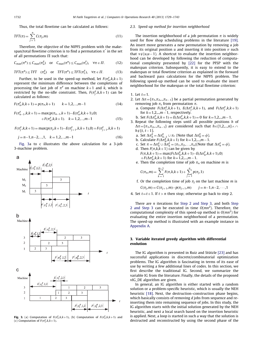
Fig. 3a to c illustrates the above calculation for a 3-job
3-machine problem.
2.3. Speed-up method for insertion neighborhood
The insertion neighborhood of a job permutation p is widely
used for flow shop scheduling problems in the literature [19].
An insert move generates a new permutation by removing a job
from its original position u and inserting it into position v such
that ve(u,u�1). A shortcut to evaluate the insertion neighbor-
hood can be developed by following the reduction of computa-
tional complexity presented by [22] for the PFSP with the
makespan criterion. Subsequently, it is easy to extend to the
makespan or total flowtime criterion as explained in the forward
and backward pass calculations for the NIPFS problem. The
following speed-up method can be used to evaluate the insert
neighborhood for the makespan or the total flowtime criterion:
1. Let t¼1.
2. Let Dp¼{p1,p2,..,pn� 1} be a partial permutation generated by
j ,k,kþ1Þ
removing job pt from permutation p.
a. Compute FðDpE
j ,k,kþ1Þ, and FðDpF
j ,k,kþ1Þ, EðDpF
for k¼1,2,..,m�1, respectively.
b. Set FðDpF
n,k,kþ1Þ ¼ EðDpF
n,k,kþ1Þ ¼ 0 for k¼1,2,..,m�1.
3. Repeat the following steps until all possible positions h of
Dp¼{p1,p2,..,pn� 1} are considered such that hA{1,2,...,n}4-
he{t, t�1}.
h ¼ DpE
a. Set DpE
b. Calculate FðDpE
c. Set p ¼ DpE
d. Then F(p,k,kþ1) can be given by
h,k,kþ1Þ for k¼1,2,...,m�1.
h ¼ fp1,p2,. . .,png(Note that DpF
h,k,kþ1Þ,0g
h�1 [ pt (Note that DpE
0 ¼ f).
h,k,kþ1Þ for k¼1,2,...,m�1.
Fðp,k,kþ1Þ ¼ maxfFðDpE
þ FðDpF
h,k,kþ1Þ�EðDpF
h [ DpF
n ¼ f).
e. Then the completion time of job pn on machine m is
X
m�1
k ¼ 1
X
n
j ¼ 1
Cðpn,mÞ ¼
Fðp,k,kþ1Þþ
pðpj,1Þ
f. Or the completion time of job pj on the last machine m is
Cðpj,mÞ ¼ Cðpjþ 1,mÞ�pðpjþ 1,mÞ
j ¼ n�1,n�2, � � � ,1
4. Set t¼tþ1. If t4n then stop; otherwise go back to step 2.
There are n iterations for Step 2 and Step 3, and both Step
2 and Step 3 can be executed in time O(mn2). Therefore, the
computational complexity of this speed-up method is O(mn2) for
evaluating the entire insertion neighborhood of a permutation.
The speed-up method is illustrated with an example instance in
Appendix A.
3. Variable iterated greedy algorithm with differential
evolution
The IG algorithm is presented in Ruiz and St ¨utzle [23] and has
successful applications in discrete/combinatorial optimization
problems. The IG algorithm is fascinating in terms of its ease of
use by writing a few additional lines of codes. In this section, we
first describe the traditional
IG. Second, we summarize the
variable IG from the literature. Finally, the details of the proposed
vIG_DE algorithm are given.
In general, an IG algorithm is either started with a random
solution or a problem-specific heuristic, which is usually the NEH
heuristic [18]. Next, the destruction–construction phase begins,
which basically consists of removing d jobs from sequence and re-
inserting them into remaining sequence of jobs. In this study, the
IG algorithm starts with the initial solution generated by the NEH
heuristic, and next a local search based on the insertion heuristic
is applied. Next, a loop is started in such a way that the solution is
destructed and reconstructed by using the second phase of the
Fig. 3. (a) Computation of FðpE
(c) Computation of FðpE
1,k,kþ1Þ.
3,k,kþ1Þ, (b) Computation of FðpE
2,k,kþ1Þ and
�
M Fatih Tasgetiren et al. / Computers & Operations Research 40 (2013) 1729–1743
1733
NEH heuristic, and then the local search based on insertion
heuristic is applied again. This process is repeated until the
termination criterion is satisfied.
The NEH heuristic contains two phases. In the first phase, jobs
are ordered in descending sums of their processing times. In the
second phase, a job permutation is established by evaluating the
partial permutations based on the initial order of the first phase.
Assume a current permutation is already determined for the first
k jobs, kþ1 and partial permutations are subsequently con-
structed by inserting job kþ1 in kþ1 into possible positions of
the current permutation. Among these kþ1 permutations, the
one generating the minimum makespan or total flowtime is kept
as the current permutation for the next iteration. Next, job kþ2
from the first phase is considered, and the process continues until
all jobs have been sequenced.
Regarding the destruction and construction procedure denoted
by DestructConstruct, in the destruction step, a given number d of
jobs are randomly chosen and removed from the solution without
repetition, thus resulting in two partial solutions. The first, with
the size d of jobs, is denoted as pR including the removed jobs in
the order in which they are removed. The second, with the size
n� d of jobs, is the original solution without the removed jobs,
which is denoted as pD. Finally, in the construction phase, the
NEH insertion heuristic is used to complete the solution. The first
1 is inserted into all possible n� dþ1 positions in the
job pR
destructed solution pD thus generating n� dþ1 partial solutions.
Among these n�dþ1 partial solutions, the best partial solution
with the minimum makespan or total flow time is chosen and
kept for the next iteration. Next, the second job pR
2 is considered
and the process continues until pR is empty or a final solution is
obtained. Therefore, pD is again of size n.
Regarding the local search algorithm, we use the referenced
insertion algorithm, called RIS, which was presented in our previous
works [28,29]. In the RIS procedure, pR is the reference permutation,
which is the best solution obtained so far. For example, suppose that
the reference permutation is given by pR¼{3, 1, 5, 2, 4} and the
current solution by p¼{4, 2, 5, 1, 3}. The RIS procedure first finds job
3 in the current permutation p. It removes job 3 from p and inserts
it into all possible positions of p. Next, the RIS procedure finds job
1 in the current permutation p. It removes job 1 and inserts it into
all possible positions of p. This procedure is repeated until pR is
empty, and a new permutation of p with n jobs is obtained. The
main concept behind the RIS procedure is the fact that the job
removal is guided by the reference permutation instead of a random
choice. It should be noted that the speed-up method explained in
Section 2.3 is employed in the NEH, DestructConstruct and RIS
procedures. The IG algorithm we implemented in this paper is
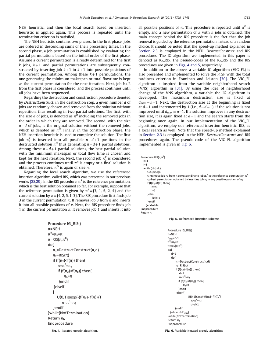
denoted as IG_RIS. The pseudo-codes of the IG_RIS and the RIS
procedures are given in Figs. 4 and 5, respectively.
The maximum destruction size
In addition to the above, a variable IG algorithm (VIG_FL) is
also presented and implemented to solve the PFSP with the total
tardiness criterion in Framinan and Leisten [30]. The VIG_FL
algorithm is inspired from the variable neighborhood search
(VNS) algorithm in [31]. By using the idea of neighborhood
change of the VNS algorithm, a variable the IG algorithm is
developed.
is fixed at
dmax ¼ n�1. Next, the destruction size at the beginning is fixed
at d¼1 and incremented by 1 (i.e., d¼dþ1), if the solution is not
improved until dmax ¼ n�1. If a solution improves in any destruc-
tion size, it is again fixed at d¼1 and the search starts from the
beginning once again.
In our implementation of the VIG_FL
algorithm, we employ our referenced insertion heuristic, RIS, as
a local search as well. Note that the speed-up method explained
in Section 2.3 is employed in the NEH, DestructConstruct and RIS
procedures again. The pseudo-code of the VIG_FL algorithm
implemented is given in Fig. 6.
Fig. 5. Referenced insertion scheme.
Fig. 4. Iterated greedy algorithm.
Fig. 6. Variable iterated greedy algorithm.
�
1734
M Fatih Tasgetiren et al. / Computers & Operations Research 40 (2013) 1729–1743
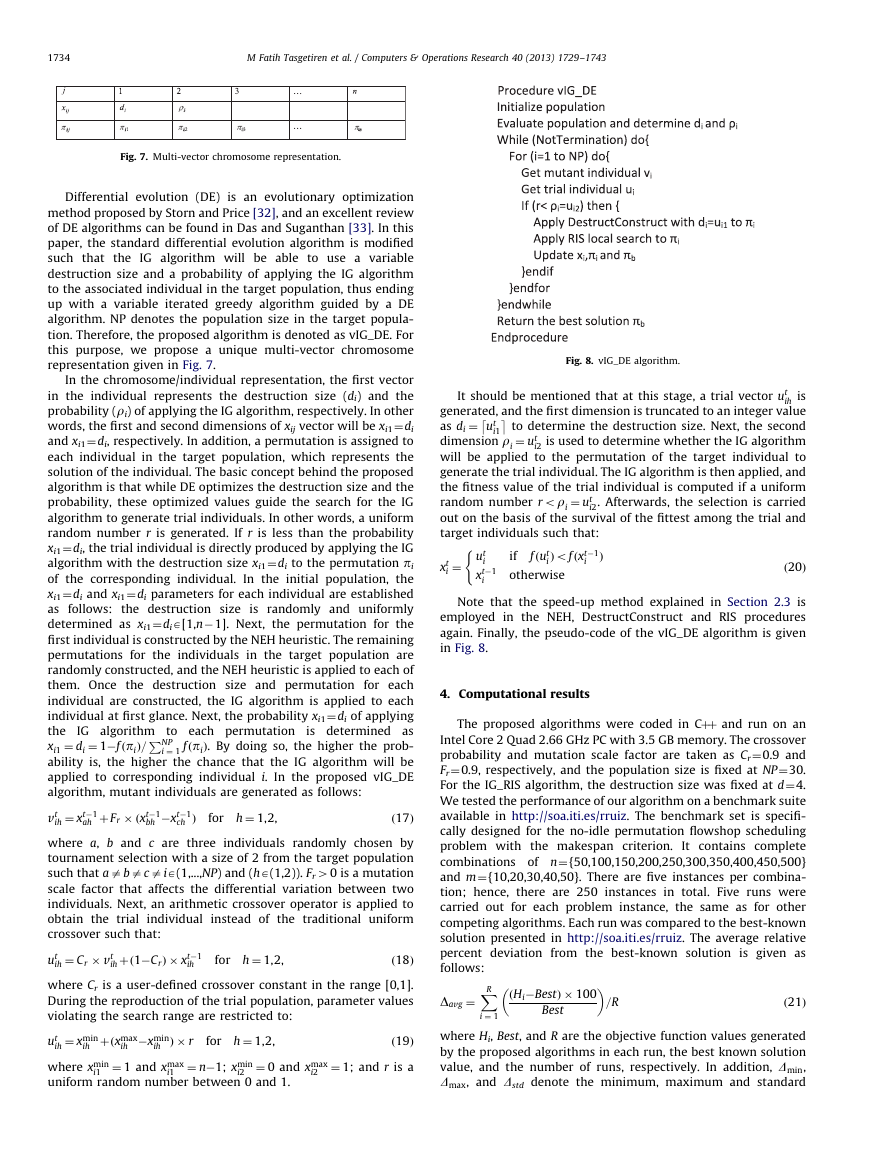
Fig. 7. Multi-vector chromosome representation.
Differential evolution (DE) is an evolutionary optimization
method proposed by Storn and Price [32], and an excellent review
of DE algorithms can be found in Das and Suganthan [33]. In this
paper, the standard differential evolution algorithm is modified
such that the IG algorithm will be able to use a variable
destruction size and a probability of applying the IG algorithm
to the associated individual in the target population, thus ending
up with a variable iterated greedy algorithm guided by a DE
algorithm. NP denotes the population size in the target popula-
tion. Therefore, the proposed algorithm is denoted as vIG_DE. For
this purpose, we propose a unique multi-vector chromosome
representation given in Fig. 7.
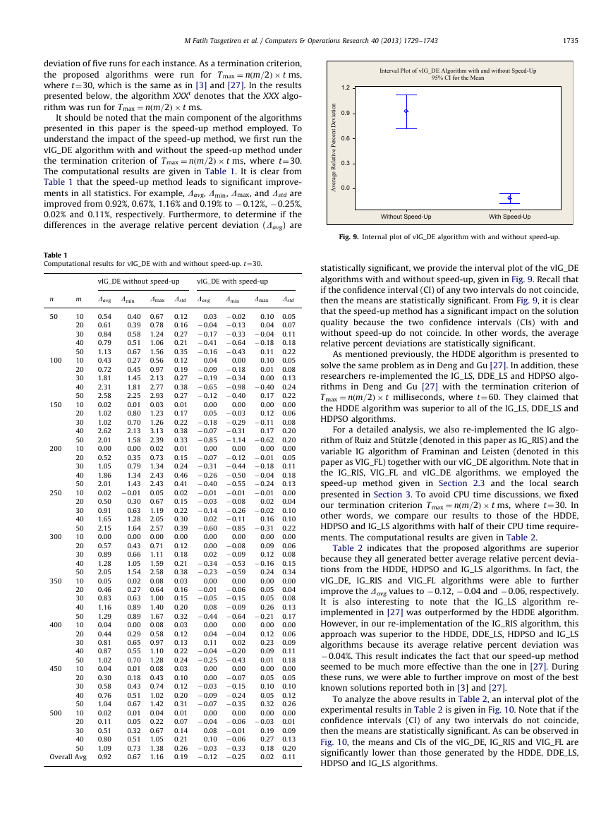
Fig. 8. vIG_DE algorithm.
In the chromosome/individual representation, the first vector
in the individual represents the destruction size (di) and the
probability (ri) of applying the IG algorithm, respectively. In other
words, the first and second dimensions of xij vector will be xi1¼di
and xi1¼ di, respectively. In addition, a permutation is assigned to
each individual in the target population, which represents the
solution of the individual. The basic concept behind the proposed
algorithm is that while DE optimizes the destruction size and the
probability, these optimized values guide the search for the IG
algorithm to generate trial individuals. In other words, a uniform
random number r is generated. If r is less than the probability
xi1¼di, the trial individual is directly produced by applying the IG
algorithm with the destruction size xi1¼di to the permutation pi
of the corresponding individual. In the initial population, the
xi1¼di and xi1¼ di parameters for each individual are established
as follows: the destruction size is randomly and uniformly
determined as xi1¼diA[1,n�1]. Next, the permutation for the
first individual is constructed by the NEH heuristic. The remaining
permutations for the individuals in the target population are
randomly constructed, and the NEH heuristic is applied to each of
them. Once the destruction size and permutation for each
individual are constructed, the IG algorithm is applied to each
P
individual at first glance. Next, the probability xi1¼di of applying
the IG algorithm to each permutation is determined as
i ¼ 1 fðpiÞ. By doing so, the higher the prob-
xi1 ¼ di ¼ 1�fðpiÞ=
ability is, the higher the chance that the IG algorithm will be
applied to corresponding individual i. In the proposed vIG_DE
algorithm, mutant individuals are generated as follows:
ih ¼ xt�1
vt
where a, b and c are three individuals randomly chosen by
tournament selection with a size of 2 from the target population
such that aabacaiA(1,...,NP) and (hA(1,2)). Fr40 is a mutation
scale factor that affects the differential variation between two
individuals. Next, an arithmetic crossover operator is applied to
obtain the trial
instead of the traditional uniform
crossover such that:
ih ¼ Cr � vt
ut
where Cr is a user-defined crossover constant in the range [0,1].
During the reproduction of the trial population, parameter values
violating the search range are restricted to:
ih ¼ xmin
ut
where xmin
uniform random number between 0 and 1.
ih þðxmax
ih Þ � r
i1 ¼ 1 and xmax
ð19Þ
i2 ¼ 1; and r is a
i2 ¼ 0 and xmax
ih þð1�CrÞ � xt�1
ah þ Fr � ðxt�1
bh �xt�1
ch Þ
i1 ¼ n�1; xmin
for h ¼ 1,2,
for h ¼ 1,2,
for h ¼ 1,2,
ih �xmin
individual
ð17Þ
ð18Þ
NP
ih
i1
�
It should be mentioned that at this stage, a trial vector ut
�
ih is
generated, and the first dimension is truncated to an integer value
as di ¼ ut
to determine the destruction size. Next, the second
dimension ri ¼ ut
i2 is used to determine whether the IG algorithm
will be applied to the permutation of the target individual to
generate the trial individual. The IG algorithm is then applied, and
the fitness value of the trial individual is computed if a uniform
random number rori ¼ ut
i2. Afterwards, the selection is carried
out on the basis of the survival of the fittest among the trial and
target individuals such that:
iÞofðxt�1
Þ
fðut
if
i
ð20Þ
(
i ¼ ut
xt
xt�1
i
i
otherwise
Note that the speed-up method explained in Section 2.3 is
employed in the NEH, DestructConstruct and RIS procedures
again. Finally, the pseudo-code of the vIG_DE algorithm is given
in Fig. 8.
4. Computational results
The proposed algorithms were coded in Cþþ and run on an
Intel Core 2 Quad 2.66 GHz PC with 3.5 GB memory. The crossover
probability and mutation scale factor are taken as Cr¼0.9 and
Fr¼0.9, respectively, and the population size is fixed at NP¼30.
For the IG_RIS algorithm, the destruction size was fixed at d¼4.
We tested the performance of our algorithm on a benchmark suite
available in http://soa.iti.es/rruiz. The benchmark set is specifi-
cally designed for the no-idle permutation flowshop scheduling
problem with the makespan criterion.
It contains complete
combinations of n¼{50,100,150,200,250,300,350,400,450,500}
and m¼{10,20,30,40,50}. There are five instances per combina-
tion; hence, there are 250 instances in total. Five runs were
carried out for each problem instance, the same as for other
competing algorithms. Each run was compared to the best-known
solution presented in http://soa.iti.es/rruiz. The average relative
percent deviation from the best-known solution is given as
follows:
X
R
�
ðHi�BestÞ � 100
�
i ¼ 1
Best
Davg ¼
=R
ð21Þ
where Hi, Best, and R are the objective function values generated
by the proposed algorithms in each run, the best known solution
value, and the number of runs, respectively. In addition, Dmin,
Dmax, and Dstd denote the minimum, maximum and standard
�
M Fatih Tasgetiren et al. / Computers & Operations Research 40 (2013) 1729–1743
1735
deviation of five runs for each instance. As a termination criterion,
the proposed algorithms were run for T max ¼ nðm=2Þ � t ms,
where t¼30, which is the same as in [3] and [27]. In the results
presented below, the algorithm XXXt denotes that the XXX algo-
rithm was run for Tmax ¼ nðm=2Þ � t ms.
It should be noted that the main component of the algorithms
presented in this paper is the speed-up method employed. To
understand the impact of the speed-up method, we first run the
vIG_DE algorithm with and without the speed-up method under
the termination criterion of Tmax ¼ nðm=2Þ � t ms, where t¼30.
The computational results are given in Table 1. It is clear from
Table 1 that the speed-up method leads to significant improve-
ments in all statistics. For example, Davg, Dmin, Dmax, and Dstd are
improved from 0.92%, 0.67%, 1.16% and 0.19% to �0.12%, �0.25%,
0.02% and 0.11%, respectively. Furthermore, to determine if the
differences in the average relative percent deviation (Davg) are
Table 1
Computational results for vIG_DE with and without speed-up. t¼30.
vIG_DE without speed-up
vIG_DE with speed-up
n
m
Davg Dmin
Dmax Dstd
Davg
Dmin
Dmax
Dstd
50
400
450
200
150
300
100
250
10
20
30
40
50
10
20
30
40
50
10
20
30
40
50
10
20
30
40
50
10
20
30
40
50
10
20
30
40
50
10
20
30
40
50
10
20
30
40
50
10
20
30
40
50
10
20
30
40
50
Overall Avg
500
350
0.54
0.40
0.61
0.39
0.84
0.58
0.79
0.51
1.13
0.67
0.43
0.27
0.72
0.45
1.81
1.45
2.31
1.81
2.58
2.25
0.02
0.01
1.02
0.80
1.02
0.70
2.62
2.13
2.01
1.58
0.00
0.00
0.52
0.35
1.05
0.79
1.86
1.34
2.01
1.43
0.02 �0.01
0.30
0.50
0.63
0.91
1.28
1.65
1.64
2.15
0.00
0.00
0.43
0.57
0.89
0.66
1.05
1.28
1.54
2.05
0.02
0.05
0.27
0.46
0.83
0.63
0.89
1.16
0.89
1.29
0.00
0.04
0.29
0.44
0.65
0.81
0.87
0.55
0.70
1.02
0.01
0.04
0.18
0.30
0.43
0.58
0.51
0.76
1.04
0.67
0.01
0.02
0.05
0.11
0.32
0.51
0.51
0.80
0.73
1.09
0.92
0.67
0.67
0.78
1.24
1.06
1.56
0.56
0.97
2.13
2.77
2.93
0.03
1.23
1.26
3.13
2.39
0.02
0.73
1.34
2.43
2.43
0.05
0.67
1.19
2.05
2.57
0.00
0.71
1.11
1.59
2.58
0.08
0.64
1.00
1.40
1.67
0.08
0.58
0.97
1.10
1.28
0.08
0.43
0.74
1.02
1.42
0.04
0.22
0.67
1.05
1.38
1.16
0.00
0.00
0.04
0.02 �0.11
0.03 �0.02
0.12
0.10
0.16 �0.04 �0.13
0.04
0.27 �0.17 �0.33 �0.04
0.21 �0.41 �0.64 �0.18
0.35 �0.16 �0.43
0.11
0.10
0.12
0.00
0.19 �0.09 �0.18
0.01
0.27 �0.19 �0.34
0.00
0.38 �0.65 �0.98 �0.40
0.27 �0.12 �0.40
0.17
0.00
0.00
0.00
0.01
0.05 �0.03
0.17
0.12
0.22 �0.18 �0.29 �0.11
0.38 �0.07 �0.31
0.17
0.33 �0.85 �1.14 �0.62
0.01
0.00
0.15 �0.07 �0.12 �0.01
0.24 �0.31 �0.44 �0.18
0.46 �0.26 �0.50 �0.04
0.41 �0.40 �0.55 �0.24
0.02 �0.01 �0.01 �0.01
0.15 �0.03 �0.08
0.02
0.22 �0.14 �0.26 �0.02
0.30
0.16
0.39 �0.60 �0.85 �0.31
0.00
0.00
0.09
0.12
0.18
0.12
0.21 �0.34 �0.53 �0.16
0.38 �0.23 �0.59
0.24
0.00
0.03
0.00
0.16 �0.01 �0.06
0.05
0.15 �0.05 �0.15
0.05
0.08 �0.09
0.20
0.26
0.32 �0.44 �0.64 �0.21
0.00
0.03
0.00
0.00
0.04 �0.04
0.12
0.12
0.23
0.13
0.02
0.11
0.22 �0.04 �0.20
0.09
0.24 �0.25 �0.43
0.01
0.00
0.00
0.00
0.03
0.00 �0.07
0.05
0.10
0.12 �0.03 �0.15
0.10
0.20 �0.09 �0.24
0.05
0.31 �0.07 �0.35
0.32
0.01
0.00
0.00
0.07 �0.04 �0.06 �0.03
0.08 �0.01
0.19
0.14
0.10 �0.06
0.27
0.21
0.26 �0.03 �0.33
0.18
0.19 �0.12 �0.25
0.02
0.00
0.00
0.00 �0.08
0.02 �0.09
0.00
0.00
0.05
0.07
0.11
0.18
0.22
0.05
0.08
0.13
0.24
0.22
0.00
0.06
0.08
0.20
0.20
0.00
0.05
0.11
0.18
0.13
0.00
0.04
0.10
0.10
0.22
0.00
0.06
0.08
0.15
0.34
0.00
0.04
0.08
0.13
0.17
0.00
0.06
0.09
0.11
0.18
0.00
0.05
0.10
0.12
0.26
0.00
0.01
0.09
0.13
0.20
0.11
Interval Plot of vIG_DE Algorithm with and without Speed-Up
95% CI for the Mean
1.2
0.9
0.6
0.3
0.0
n
o
i
t
a
i
v
e
D
t
n
e
c
r
e
P
e
v
i
t
a
l
e
R
e
g
a
r
e
v
A
Without Speed-Up
With Speed-Up
Fig. 9. Internal plot of vIG_DE algorithm with and without speed-up.
statistically significant, we provide the interval plot of the vIG_DE
algorithms with and without speed-up, given in Fig. 9. Recall that
if the confidence interval (CI) of any two intervals do not coincide,
then the means are statistically significant. From Fig. 9, it is clear
that the speed-up method has a significant impact on the solution
quality because the two confidence intervals (CIs) with and
without speed-up do not coincide. In other words, the average
relative percent deviations are statistically significant.
As mentioned previously, the HDDE algorithm is presented to
solve the same problem as in Deng and Gu [27]. In addition, these
researchers re-implemented the IG_LS, DDE_LS and HDPSO algo-
rithms in Deng and Gu [27] with the termination criterion of
Tmax ¼ nðm=2Þ � t milliseconds, where t¼60. They claimed that
the HDDE algorithm was superior to all of the IG_LS, DDE_LS and
HDPSO algorithms.
For a detailed analysis, we also re-implemented the IG algo-
rithm of Ruiz and St ¨utzle (denoted in this paper as IG_RIS) and the
variable IG algorithm of Framinan and Leisten (denoted in this
paper as VIG_FL) together with our vIG_DE algorithm. Note that in
the IG_RIS, VIG_FL and vIG_DE algorithms, we employed the
speed-up method given in Section 2.3 and the local search
presented in Section 3. To avoid CPU time discussions, we fixed
our termination criterion T max ¼ nðm=2Þ � t ms, where t¼30. In
other words, we compare our results to those of the HDDE,
HDPSO and IG_LS algorithms with half of their CPU time require-
ments. The computational results are given in Table 2.
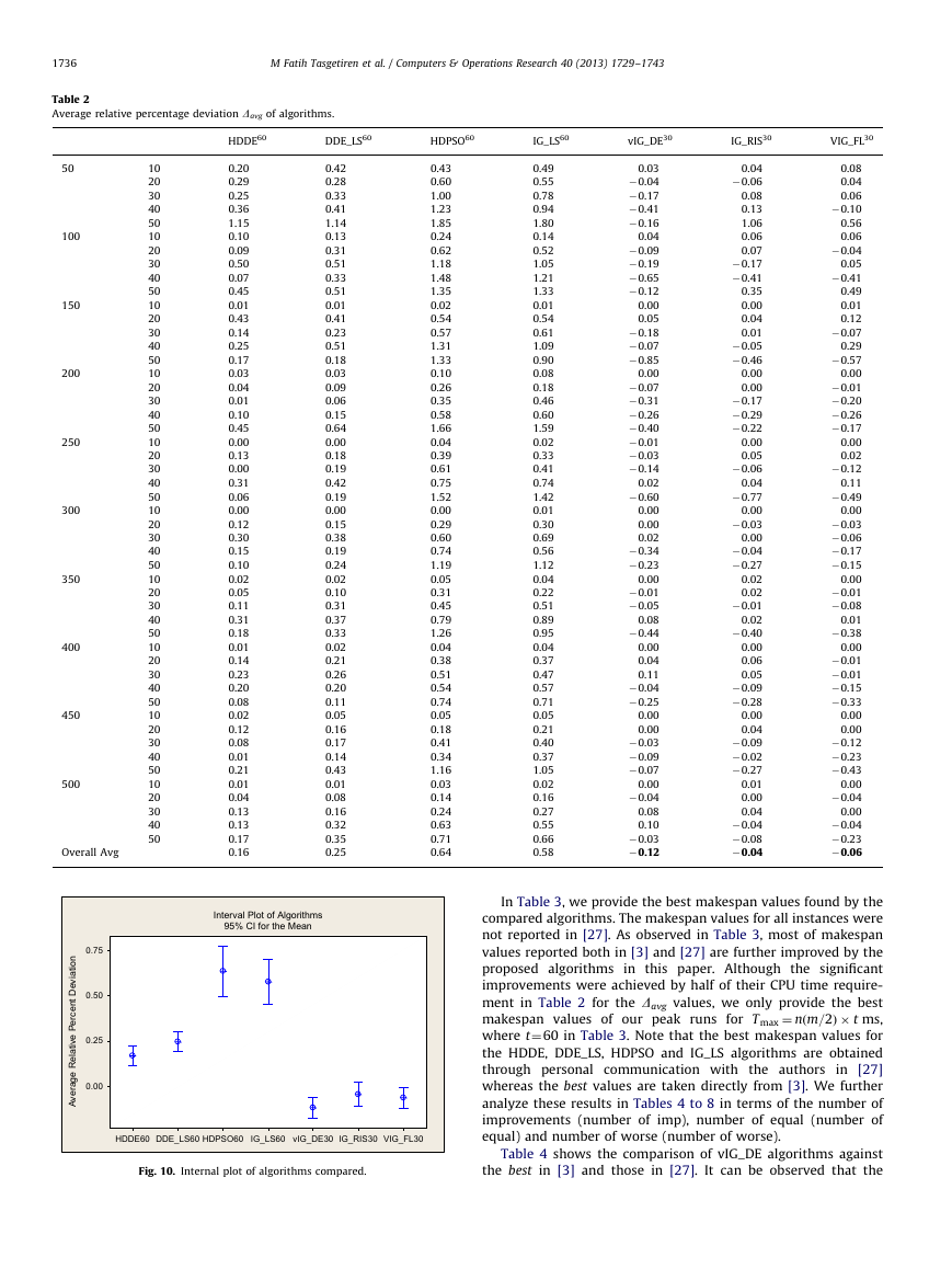
Table 2 indicates that the proposed algorithms are superior
because they all generated better average relative percent devia-
tions from the HDDE, HDPSO and IG_LS algorithms. In fact, the
vIG_DE,
IG_RIS and VIG_FL algorithms were able to further
improve the Davg values to �0.12, �0.04 and �0.06, respectively.
It is also interesting to note that the IG_LS algorithm re-
implemented in [27] was outperformed by the HDDE algorithm.
However, in our re-implementation of the IG_RIS algorithm, this
approach was superior to the HDDE, DDE_LS, HDPSO and IG_LS
algorithms because its average relative percent deviation was
�0.04%. This result indicates the fact that our speed-up method
seemed to be much more effective than the one in [27]. During
these runs, we were able to further improve on most of the best
known solutions reported both in [3] and [27].
To analyze the above results in Table 2, an interval plot of the
experimental results in Table 2 is given in Fig. 10. Note that if the
confidence intervals (CI) of any two intervals do not coincide,
then the means are statistically significant. As can be observed in
Fig. 10, the means and CIs of the vIG_DE, IG_RIS and VIG_FL are
significantly lower than those generated by the HDDE, DDE_LS,
HDPSO and IG_LS algorithms.
�
1736
M Fatih Tasgetiren et al. / Computers & Operations Research 40 (2013) 1729–1743
Table 2
Average relative percentage deviation Davg of algorithms.
HDDE60
DDE_LS60
HDPSO60
IG_LS60
vIG_DE30
IG_RIS30
VIG_FL30
10
20
30
40
50
10
20
30
40
50
10
20
30
40
50
10
20
30
40
50
10
20
30
40
50
10
20
30
40
50
10
20
30
40
50
10
20
30
40
50
10
20
30
40
50
10
20
30
40
50
50
100
150
200
250
300
350
400
450
500
Overall Avg
0.75
n
o
0.20
0.29
0.25
0.36
1.15
0.10
0.09
0.50
0.07
0.45
0.01
0.43
0.14
0.25
0.17
0.03
0.04
0.01
0.10
0.45
0.00
0.13
0.00
0.31
0.06
0.00
0.12
0.30
0.15
0.10
0.02
0.05
0.11
0.31
0.18
0.01
0.14
0.23
0.20
0.08
0.02
0.12
0.08
0.01
0.21
0.01
0.04
0.13
0.13
0.17
0.16
0.42
0.28
0.33
0.41
1.14
0.13
0.31
0.51
0.33
0.51
0.01
0.41
0.23
0.51
0.18
0.03
0.09
0.06
0.15
0.64
0.00
0.18
0.19
0.42
0.19
0.00
0.15
0.38
0.19
0.24
0.02
0.10
0.31
0.37
0.33
0.02
0.21
0.26
0.20
0.11
0.05
0.16
0.17
0.14
0.43
0.01
0.08
0.16
0.32
0.35
0.25
Interval Plot of Algorithms
95% CI for the Mean
i
t
i
a
v
e
D
t
n
e
c
r
e
P
e
v
i
t
l
a
e
R
e
g
a
r
e
v
A
0.50
0.25
0.00
HDDE60
DDE_LS60
HDPSO60
IG_LS60
vIG_DE30
IG_RIS30
VIG_FL30
Fig. 10. Internal plot of algorithms compared.
0.43
0.60
1.00
1.23
1.85
0.24
0.62
1.18
1.48
1.35
0.02
0.54
0.57
1.31
1.33
0.10
0.26
0.35
0.58
1.66
0.04
0.39
0.61
0.75
1.52
0.00
0.29
0.60
0.74
1.19
0.05
0.31
0.45
0.79
1.26
0.04
0.38
0.51
0.54
0.74
0.05
0.18
0.41
0.34
1.16
0.03
0.14
0.24
0.63
0.71
0.64
0.49
0.55
0.78
0.94
1.80
0.14
0.52
1.05
1.21
1.33
0.01
0.54
0.61
1.09
0.90
0.08
0.18
0.46
0.60
1.59
0.02
0.33
0.41
0.74
1.42
0.01
0.30
0.69
0.56
1.12
0.04
0.22
0.51
0.89
0.95
0.04
0.37
0.47
0.57
0.71
0.05
0.21
0.40
0.37
1.05
0.02
0.16
0.27
0.55
0.66
0.58
0.03
�0.04
�0.17
�0.41
�0.16
0.04
�0.09
�0.19
�0.65
�0.12
0.00
0.05
�0.18
�0.07
�0.85
0.00
�0.07
�0.31
�0.26
�0.40
�0.01
�0.03
�0.14
0.02
�0.60
0.00
0.00
0.02
�0.34
�0.23
0.00
�0.01
�0.05
0.08
�0.44
0.00
0.04
0.11
�0.04
�0.25
0.00
0.00
�0.03
�0.09
�0.07
0.00
�0.04
0.08
0.10
�0.03
�0.12
0.04
�0.06
0.08
0.13
1.06
0.06
0.07
�0.17
�0.41
0.35
0.00
0.04
0.01
�0.05
�0.46
0.00
0.00
�0.17
�0.29
�0.22
0.00
0.05
�0.06
0.04
�0.77
0.00
�0.03
0.00
�0.04
�0.27
0.02
0.02
�0.01
0.02
�0.40
0.00
0.06
0.05
�0.09
�0.28
0.00
0.04
�0.09
�0.02
�0.27
0.01
0.00
0.04
�0.04
�0.08
�0.04
0.08
0.04
0.06
�0.10
0.56
0.06
�0.04
0.05
�0.41
0.49
0.01
0.12
�0.07
0.29
�0.57
0.00
�0.01
�0.20
�0.26
�0.17
0.00
0.02
�0.12
0.11
�0.49
0.00
�0.03
�0.06
�0.17
�0.15
0.00
�0.01
�0.08
0.01
�0.38
0.00
�0.01
�0.01
�0.15
�0.33
0.00
0.00
�0.12
�0.23
�0.43
0.00
�0.04
0.00
�0.04
�0.23
�0.06
In Table 3, we provide the best makespan values found by the
compared algorithms. The makespan values for all instances were
not reported in [27]. As observed in Table 3, most of makespan
values reported both in [3] and [27] are further improved by the
proposed algorithms in this paper. Although the significant
improvements were achieved by half of their CPU time require-
ment in Table 2 for the Davg values, we only provide the best
makespan values of our peak runs for T max ¼ nðm=2Þ � t ms,
where t¼60 in Table 3. Note that the best makespan values for
the HDDE, DDE_LS, HDPSO and IG_LS algorithms are obtained
through personal communication with the authors in [27]
whereas the best values are taken directly from [3]. We further
analyze these results in Tables 4 to 8 in terms of the number of
improvements (number of imp), number of equal (number of
equal) and number of worse (number of worse).
Table 4 shows the comparison of vIG_DE algorithms against
the best in [3] and those in [27]. It can be observed that the
�



 2023年江西萍乡中考道德与法治真题及答案.doc
 2012年重庆南川中考生物真题及答案.doc
 2013年江西师范大学地理学综合及文艺理论基础考研真题.doc
 2020年四川甘孜小升初语文真题及答案I卷.doc
 2020年注册岩土工程师专业基础考试真题及答案.doc
 2023-2024学年福建省厦门市九年级上学期数学月考试题及答案.doc
 2021-2022学年辽宁省沈阳市大东区九年级上学期语文期末试题及答案.doc
 2022-2023学年北京东城区初三第一学期物理期末试卷及答案.doc
 2018上半年江西教师资格初中地理学科知识与教学能力真题及答案.doc
 2012年河北国家公务员申论考试真题及答案-省级.doc
 2020-2021学年江苏省扬州市江都区邵樊片九年级上学期数学第一次质量检测试题及答案.doc
 2022下半年黑龙江教师资格证中学综合素质真题及答案.doc