Cover
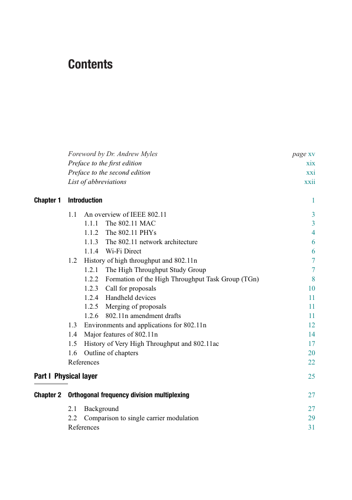
Contents
Foreword
Preface to the first edition
Preface to the second edition
Abbreviations
1 Introduction
1.1 An overview of IEEE 802.11
1.1.1 The 802.11 MAC
1.1.2 The 802.11 PHYs
1.1.3 The 802.11 network architecture
1.1.4 Wi-Fi Direct
1.2 History of high throughput and 802.11n
1.2.1 The High Throughput Study Group
1.2.2 Formation of the High Throughput Task Group (TGn)
1.2.3 Call for proposals
1.2.4 Handheld devices
1.2.5 Merging of proposals
1.2.6 802.11n amendment drafts
1.3 Environments and applications for 802.11n
1.4 Major features of 802.11n
1.5 History of Very High Throughput and 802.11ac
1.6 Outline of chapters
References
Part I Physical layer
2 Orthogonal frequency division multiplexing
2.1 Background
2.2 Comparison to single carrier modulation
References
3 MIMO/SDM basics
3.1 SISO (802.11a/g) background
3.2 MIMO basics
3.3 SDM basics
3.4 MIMO environment
3.5 802.11n and 802.11ac propagation model
3.5.1 Impulse response
3.5.2 Antenna correlation
3.5.2.1 Correlation coefficient
3.5.3 802.11n Doppler model
3.5.3.1 Modified Doppler model for channel model F
3.5.4 802.11ac Doppler model
3.5.5 Physical layer impairments
3.5.5.1 Phase noise
3.5.5.2 Power amplifier non-linearity
3.5.6 Path loss
3.6 Linear receiver design
3.7 Maximum likelihood estimation
References
Appendix 3.1: 802.11n channel models
4 PHY interoperability with 11a/g legacy OFDM devices
4.1 11a packet structure review
4.1.1 Short Training field
4.1.2 Long Training field
4.1.3 Signal field
4.1.4 Data field
4.1.5 Packet encoding process
4.1.6 Receive procedure
4.2 Mixed format high throughput packet structure
4.2.1 Non-HT portion of the MF preamble
4.2.1.1 Cyclic shifts
4.2.1.2 Legacy compatibility
4.2.1.3 Non-HT Short Training field
4.2.1.4 Non-HT Long Training field
4.2.2 HT portion of the MF preamble
4.2.2.1 High Throughput Signal field
4.2.2.2 High Throughput Short Training field
4.2.2.3 High Throughput Long Training field
4.2.3 Data field
4.2.3.1 Bit string
4.2.3.2 Scrambling and encoding
4.2.3.3 Stream parsing
4.2.3.4 Interleaving
4.2.3.5 Modulation mapping
4.2.3.6 Pilot subcarriers
4.2.4 HT MF receive procedure
4.2.4.1 RF front end
4.2.4.2 Legacy part of the preamble
4.2.4.3 High Throughput Signal field (HT-SIG)
4.2.4.4 High Throughput Training fields and MIMO channel estimation
4.2.4.6 Demapping, deinterleaving, decoding, and descrambling
References
Appendix 4.1: 20 MHz basic MCS tables
5 High throughput
5.1 40 MHz channel
5.1.1 40 MHz subcarrier design and spectral mask
5.1.2 40 MHz channel design
5.1.3 40 MHz mixed format preamble
5.1.4 40 MHz data encoding
5.1.4.1 Bit string with two encoders
5.1.4.2 Scrambling, encoder parsing, and encoding with two encoders
5.1.4.3 Stream parsing with two encoders
5.1.4.4 Interleaver design for 40 MHz
5.1.5 MCS 32: high throughput duplicate format
5.1.6 20/40 MHz coexistence with legacy in the PHY
5.1.7 Performance improvement with 40 MHz
5.2 20 MHz enhancements: additional data subcarriers
5.3 MCS enhancements: spatial streams and code rate
5.4 Greenfield (GF) preamble
5.4.1 Format of the GF preamble
5.4.2 PHY efficiency
5.4.3 Issues with GF
5.4.3.1 Network efficiency
5.4.3.2 Interoperability issues with legacy
5.4.3.3 Implementation issues
5.4.4 Preamble auto-detection
5.5 Short guard interval
References
Appendix 5.1: Channel allocation
Appendix 5.2: 40 MHz basic MCS tables
Appendix 5.3: Physical layer waveform parameters
6 Robust performance
6.1 Receive diversity
6.1.1 Maximal ratio combining basics
6.1.2 MIMO performance improvement with receive diversity
6.1.3 Selection diversity
6.2 Spatial expansion
6.3 Space-time block coding
6.3.1 Alamouti scheme background
6.3.2 Additional STBC antenna configurations
6.3.3 STBC receiver and equalization
6.3.4 Transmission and packet encoding process with STBC
6.4 Low density parity check codes
6.4.1 LDPC encoding process
6.4.1.1 Step 1: Calculating the minimum number of OFDM symbols
6.4.1.2 Step 2: Determining the code word size and number of code words
6.4.1.3 Step 3: Determining the number of shortening zero bits
6.4.1.4 Step 4: Generating the parity bits
6.4.1.5 Step 5: Packing into OFDM symbols
Puncturing
Repetition
6.4.1.6 Step 6: Stream parsing
6.4.2 Effective code rate
6.4.3 LDPC coding gain
References
Appendix 6.1: Parity check matrices
7 Very High Throughput PHY
7.1 Channelization
7.2 Single user (SU) VHT packet structure
7.3 VHT format preamble
7.3.1 Non-VHT portion of the VHT format preamble
7.3.1.1 Non-VHT short training field
7.3.1.2 Non-VHT long training field
7.3.1.3 Non-VHT signal field
7.3.2 VHT portion of the VHT format preamble
7.3.2.1 VHT signal field A
7.3.2.2 VHT short training field
7.3.2.4 VHT signal field B
7.3.3 VHT data field
7.3.3.1 PHY transmitter flow
7.3.3.2 Service field
7.3.3.3 Encoding
BCC encoder parser for SU
LDPC coding for SU
7.3.3.4 Stream parsing
7.3.3.5 160 MHz frequency segment parsing
7.3.3.6 BCC interleaving
7.3.3.7 256-QAM modulation mapping
7.3.3.8 LDPC subcarrier mapper
7.3.3.9 Segment deparser for 160 MHz
7.3.3.10 Pilot subcarriers
7.3.3.11 Time domain waveform
7.4 Modulation coding scheme
References
Part II Medium access control layer
8 Medium access control
8.1 Protocol layering
8.2 Finding, joining, and leaving a BSS
8.2.1 Beacons
8.2.2 Scanning
8.2.3 Authentication
8.2.4 Association
8.2.5 Reassociation
8.2.6 Disassociation
8.2.7 802.1X Authentication
8.2.8 Key distribution
8.3 Distributed channel access
8.3.1 Basic channel access timing
8.3.1.1 SIFS
8.3.1.2 Slot time
8.3.1.3 PIFS
8.3.1.4 DIFS
8.3.1.5 Random backoff time
8.3.1.6 Random backoff procedure
8.4 Data/ACK frame exchange
8.4.1 Fragmentation
8.4.2 Duplicate detection
8.4.3 Data/ACK sequence overhead and fairness
8.5 Hidden node problem
8.5.1 Network allocation vector (NAV)
8.5.1.1 RTS/CTS frame exchange
8.5.2 EIFS
8.6 Enhanced distributed channel access
8.6.1 Transmit opportunity
8.6.2 Channel access timing with EDCA
8.6.3 EDCA access parameters
8.6.4 EIFS revisited
8.6.5 Collision detect
8.6.6 QoS Data frame
8.7 Block acknowledgement
8.7.1 Block data frame exchange
8.8 Power management
8.8.1 AP TIM transmissions
8.8.2 PS mode operation
8.8.3 WNM-Sleep
8.8.4 SM power save
8.8.5 Operating Mode Notification
References
9 MAC throughput enhancements
9.1 Reasons for change
9.1.1 Throughput without MAC changes
9.1.2 MAC throughput enhancements
9.1.3 Throughput with MAC efficiency enhancements
9.2 Aggregation
9.2.1 Aggregate MSDU (A-MSDU)
9.2.2 Aggregate MPDU (A-MPDU)
9.2.2.1 A-MPDU contents
9.2.2.2 A-MPDU length and MPDU spacing constraints
9.2.3 Aggregate PSDU (A-PSDU)
9.2.4 A-MPDU in VHT PPDUs
9.2.5 VHT single MPDU
9.3 Block acknowledgement
9.3.1 Immediate and delayed block ack
9.3.2 Block ack session initiation
9.3.3 Block ack session data transfer
9.3.4 Block ack session tear down
9.3.5 Normal ack policy in a non-aggregate
9.3.6 Reorder buffer operation
9.4 HT-immediate block ack
9.4.1 Normal Ack policy in an aggregate
9.4.2 Compressed block ack
9.4.3 Full state and partial state block ack
9.4.3.1 Full state block ack operation
9.4.3.2 Motivation for partial state block ack
9.4.3.3 Partial state block ack operation
9.4.4 HT-immediate block ack TXOP sequences
9.5 HT-delayed block ack
9.5.1 HT-delayed block ack TXOP sequences
10 Advanced channel access techniques
10.1 PCF
10.1.1 Establishing the CFP
10.1.2 NAV during the CFP
10.1.3 Data transfer during the CFP
10.1.3.1 Contention-free acknowledgement
10.1.4 PCF limitations
10.2 HCCA
10.2.1 Traffic streams
10.2.1.1 TS setup and maintenance
10.2.1.2 Data transfer
10.2.1.3 TS deletion
10.2.2 Controlled access phases
10.2.3 Polled TXOP
10.2.4 TXOP requests
10.2.5 Use of RTS/CTS
10.2.6 HCCA limitations
10.3 Reverse direction protocol
10.3.1 Reverse direction frame exchange
10.3.2 Reverse direction rules
10.3.3 Error recovery
10.4 PSMP
10.4.1 PSMP recovery
10.4.2 PSMP burst
10.4.3 Resource allocation
10.4.4 Block ack usage under PSMP
References
11 Interoperability and coexistence
11.1 Station capabilities and operation
11.1.1 HT station PHY capabilities
11.1.2 VHT station PHY capabilities
11.1.3 HT station MAC capabilities
11.1.4 VHT station MAC capabilities
11.1.5 Advanced capabilities
11.2 BSS operation
11.2.1 Beacon transmission
11.2.2 20MHz BSS operation
11.2.3 20/40MHz HT BSS operation
11.2.3.1 20/40MHz operation in the 5 GHz bands
11.2.3.2 20/40MHz operation in the 2.4 GHz band
11.2.3.3 A brief history of 40MHz in the 2.4 GHz band
11.2.4 VHT BSS operation
11.2.5 OBSS scanning requirements
11.2.5.1 Establishing a 20/40MHz BSS in the 5 GHz bands
11.2.5.2 Establishing a 20/40MHz BSS in the 2.4 GHz band
11.2.5.3 OBSS scanning during 20/40MHz BSS operation
11.2.5.4 Scanning requirements for 20/40MHz stations
11.2.6 Signaling 40MHz intolerance
11.2.7 Channel management at the AP
11.2.8 Establishing a VHT BSS in the 5 GHz band
11.3 A summary of fields controlling 40MHz operation
11.4 Channel access in wider channels
11.4.1 Overlapping BSSs
11.4.2 Wide channel access using RTS/CTS
11.4.3 TXOP rules for wide channel access
11.4.4 Clear channel assessment
11.4.4.1 CCA in 20MHz
11.4.4.2 CCA with the HT PHY
11.4.4.3 CCA with the VHT PHY
11.4.5 NAV assertion in an HT and VHT BSS
11.5 Protection
11.5.1 Protection with 802.11b stations present
11.5.2 Protection with 802.11g or 802.11a stations present
11.5.3 Protection for OBSS legacy stations
11.5.4 RIFS burst protection
11.5.5 HT Greenfield format protection
11.5.6 RTS/CTS protection
11.5.7 CTS-to-Self protection
11.5.8 Protection using a non-HT, HT mixed, or VHT PPDU with non-HT response
11.5.9 Non-HT station deferral with HT mixed and VHT format PPDUs
11.5.10 L-SIG TXOP protection
11.6 Phased coexistence operation (PCO)
11.6.1 Basic operation
11.6.2 Minimizing real-time disruption
References
12 MAC frame formats
12.1 General frame format
12.1.1 Frame Control field
12.1.1.1 Protocol Version field
12.1.1.2 Type and Subtype fields
12.1.1.3 To DS and From DS fields
12.1.1.4 More Fragments field
12.1.1.5 Retry field
12.1.1.6 Power Management field
12.1.1.7 More Data field
12.1.1.8 Protected Frame field
12.1.1.9 Order field
12.1.2 Duration/ID field
12.1.3 Address fields
12.1.4 Sequence Control field
12.1.5 QoS Control field
12.1.5.1 TXOP Limit subfield
12.1.5.2 Queue Size subfield
12.1.5.3 TXOP Duration Requested subfield
12.1.5.4 AP PS Buffer State subfield
12.1.6 HT Control field
12.1.6.1 HT variant HT Control field
12.1.6.2 VHT variant HT Control field
12.1.6.3 Fields common to both the HT and VHT variants
12.1.7 Frame Body field
12.1.8 FCS field
12.2 Format of individual frame types
12.2.1 Control frames
12.2.1.1 RTS
12.2.1.2 CTS
12.2.1.3 ACK
12.2.1.4 BAR
12.2.1.5 Multi-TID BAR
12.2.1.6 BA
12.2.1.7 Multi-TID BA
12.2.1.8 PS-Poll
12.2.1.9 CF-End and CF-End+CF-Ack
12.2.1.10 Control Wrapper
12.2.1.11 VHT NDP Announcement
12.2.1.12 Beamforming Report Poll
12.2.2 Data frames
12.2.3 Management frames
12.2.3.1 Beacon frame
12.2.3.2 Association and Reassociation Request frame
12.2.3.3 Association and Reassociation Response frame
12.2.3.4 Disassociation frame
12.2.3.5 Probe Request frame
12.2.3.6 Probe Response frame
12.2.3.7 Authentication frame
12.2.3.8 Deauthentication frame
12.2.3.9 Action and Action No Ack frames
Spectrum management action frames
QoS action frames
DLS Action frames
Block Ack Action frames
HT Action frames
Public Action frames
12.3 Management frame fields
12.3.1 Fields that are not information elements
12.3.1.1 Capability Information field
12.3.2 Information elements
12.3.2.1 Extended Channel Switch Announcement element
12.3.2.2 HT Capabilities element
HT Capabilities Info and HT Extended Capabilities fields
A-MPDU Parameters
Supported MCS Set field
Transmit Beamforming Capabilities field
Antenna Selection Capability field
12.3.2.3 HT Operation element
12.3.2.4 20/40 BSS Coexistence element
12.3.2.5 20/40 BSS Intolerant Channel Report element
12.3.2.6 Overlapping BSS Scan Parameters element
12.3.2.7 VHT Capabilities element
12.3.2.8 VHT Operation element
References
Part III Transmit beamforming, multi-user MIMO, and fast link adaptation
13 Transmit beamforming
13.1 Singular value decomposition
13.2 Transmit beamforming with SVD
13.3 Eigenvalue analysis
13.4 Unequal MCS
13.5 Receiver design
13.6 Channel sounding
13.7 Channel state information feedback
13.7.1 Implicit feedback
13.7.2 Explicit feedback
13.7.2.1 CSI feedback
13.7.2.2 Non-compressed beamforming weights feedback
13.7.2.3 Compressed beamforming weights feedback
13.8 Improved performance with transmit beamforming
13.9 Degradations
13.10 MAC considerations
13.10.1 Sounding PPDUs
13.10.1.1 NDP as sounding PPDU
13.10.1.2 NDP use for calibration and antenna selection
13.10.2 Implicit feedback beamforming
13.10.2.1 Calibration
Calibration exchange using staggered sounding PPDUs
Calibration exchange using NDP
13.10.2.2 Sequences using implicit feedback
13.10.3 Explicit feedback beamforming
13.10.3.1 Sequences using explicit feedback
13.10.3.2 Differences between NDP and staggered sounding
13.11 Comparison between implicit and explicit
13.12 Transmit beamforming in 802.11ac
13.12.1 VHT sounding protocol
References
Appendix 13.1: Unequal MCS for 802.11n
Unequal MCS for 20 MHz
Unequal MCS for 40 MHz
14 Multi-user MIMO
14.1 MU-MIMO pre-coding
14.2 Receiver design
14.3 PHY considerations
14.3.1 VHT MU preamble
14.3.1.1 VHT-SIG-A
14.3.1.2 VHT-STF
14.3.1.3 VHT-LTF
14.3.1.4 VHT-SIG-B
14.3.2 VHT MU data field
14.3.2.1 Encoding for MU
BCC encoder parser for MU
LDPC and BCC coding for MU
14.3.2.2 Other data field modifications for MU
14.3.3 Compressed beamforming matrices
14.4 Group ID
14.4.1 Receive operation
14.4.2 Group ID management
14.5 MAC support for MU-MIMO
14.5.1 MU aggregation
14.5.2 MU acknowledgements
14.5.3 EDCA TXOPs for MU sequences
14.5.4 TXOP sharing
14.6 VHT sounding protocol for MU-MIMO
14.6.1 The basic sounding exchange
14.6.2 Support for fragmentation
References
15 Fast link adaptation
15.1 MCS feedback
15.2 MCS feedback mechanisms
15.3 MCS feedback using the HT variant HT Control field
15.4 MCS feedback using the VHT variant HT Control field
Index





 2023年江西萍乡中考道德与法治真题及答案.doc
 2012年重庆南川中考生物真题及答案.doc
 2013年江西师范大学地理学综合及文艺理论基础考研真题.doc
 2020年四川甘孜小升初语文真题及答案I卷.doc
 2020年注册岩土工程师专业基础考试真题及答案.doc
 2023-2024学年福建省厦门市九年级上学期数学月考试题及答案.doc
 2021-2022学年辽宁省沈阳市大东区九年级上学期语文期末试题及答案.doc
 2022-2023学年北京东城区初三第一学期物理期末试卷及答案.doc
 2018上半年江西教师资格初中地理学科知识与教学能力真题及答案.doc
 2012年河北国家公务员申论考试真题及答案-省级.doc
 2020-2021学年江苏省扬州市江都区邵樊片九年级上学期数学第一次质量检测试题及答案.doc
 2022下半年黑龙江教师资格证中学综合素质真题及答案.doc