Vienna LTE Simulators
System Level Simulator Documentation, v1.8r1375
1
Institute of Telecommunications
Vienna University of Technology, Austria
Gusshausstrasse 25/389, A-1040 Vienna, Austria
Email: {mtaranet}{mmueller}@nt.tuwien.ac.at
Web: http://www.nt.tuwien.ac.at/ltesimulator
Abstract
This document contains documentation on how to use the LTE System Level Simulator (LTE SL Simulator) [1] as well as
some insight on its structure and the assumptions that were made while developing it. This document relates more on how to
actually use the simulator. The concept and the structure of the simulator is described in more detail in [2].
I. FOREWORD
The LTE SL Simulator is published under a non-commercial academic use license. Please make sure that you understand
the terms and conditions of the license before you use any of the available software packages. Would you require a license
different to a non-commercial academic one please contact Josep Colom Ikuno or Martin Taranetz.
The detailed license agreement for the LTE SL Simulator can be found in Section XXIII. Please read it carefully and keep
in mind that the usage of the simulator is subjected to compliance with the license terms.
�
I
II
III
IV
V
Foreword
Running a simulation
CONTENTS
.
.
.
.
.
.
.
.
.
.
.
.
.
.
.
.
.
.
.
.
.
.
.
.
.
.
.
.
.
.
.
.
.
.
.
.
.
.
.
Simulation parameters
. . . . . . . . . . . . . . . . . . . . . . . . . . . . . . . . . . . .
.
Debug options .
III-A
. . . . . . . . . . . . . . . . . . . . . . . . . . . . . . . . . . . .
Plotting options
III-B
.
. . . . . . . . . . . . . . . . . . . . . . . . . . . . . . . . . . . .
General parameters
III-C
. . . . . . . . . . . . . . . . . . . . . . . . . . . . . . . . . .
III-D
Random number generation options
. . . . . . . . . . . . . . . . . . . . . . . . . . . . . . . . . . . .
Simulation time .
III-E
Cache options .
III-F
. . . . . . . . . . . . . . . . . . . . . . . . . . . . . . . . . . . .
.
Network layout and macroscopic pathloss parameters . . . . . . . . . . . . . . . . . . . . . . . . .
III-G
III-G1
. . . . . . . . . . . . . . . . . . . . . . . . . . . . . . .
Generated network parameters
III-G2
Capesso-imported network parameters . . . . . . . . . . . . . . . . . . . . . . . . . . .
Shadow fading (only for generated networks) . . . . . . . . . . . . . . . . . . . . . . . . . . . . .
. . . . . . . . . . . . . . . . . . . . . . . . . . . . . . . . . . . .
Small-scale fading .
. . . . . . . . . . . . . . . . . . . . . . . . . . . . . . . . . . . .
UE settings .
.
.
eNodeB settings .
.
. . . . . . . . . . . . . . . . . . . . . . . . . . . . . . . . . . . .
. . . . . . . . . . . . . . . . . . . . . . . . . . . . . . . . . . . .
Scheduler settings .
. . . . . . . . . . . . . . . . . . . . . . . . . . . . . . . . . . . .
. . . . . . . . . . . . . . . . . . . . . . . . . . . . . . . . . . . .
. . . . . . . . . . . . . . . . . . . . . . . . . . . . . . . . . . . .
. . . . . . . . . . . . . . . . . . . . . . . . . . . . . . . . . . . .
. . . . . . . . . . . . . . . . . . . . . . . . . . . . . . . . . . .
III-H
.
III-I
.
III-J
.
III-K
III-L
.
III-M CQI mapper options .
III-N
III-O
III-P
III-Q
.
.
.
.
.
.
.
.
.
.
.
Uplink channel options .
.
.
SINR averaging .
.
Saving the results .
.
.
Optional configuration parameters
.
.
.
.
.
.
.
.
.
.
.
.
.
.
.
.
.
.
.
.
.
.
.
.
.
.
.
.
.
.
.
.
.
.
.
Implementation issues
IV-A
IV-B
IV-C
IV-D
.
.
How to read the pathloss maps .
. . . . . . . . . . . . . . . . . . . . . . . . . . . . . . . . . . . .
.
Antenna azimuth .
.
Remote Radio Head (RRH) .
. . . . . . . . . . . . . . . . . . . . . . . . . . . . . . . . . . .
.
.
Block Error Ratio curves and CQI mapping . . . . . . . . . . . . . . . . . . . . . . . . . . . . . .
. . . . . . . . . . . . . . . . . . . . . . . . . . . . . . . . . .
.
.
.
.
.
.
.
Plotting results
V-A
V-B
eNodeB and UE position .
. . . . . . . . . . . . . . . . . . . . . . . . . . . . . . . . . . . .
Throughput and aggregate results . . . . . . . . . . . . . . . . . . . . . . . . . . . . . . . . . . . .
.
.
.
.
.
.
.
.
.
.
.
.
.
.
.
.
.
.
.
.
.
.
.
.
.
.
.
.
.
.
.
.
.
.
.
.
.
.
.
.
.
.
.
.
.
.
.
.
.
.
.
.
.
.
.
.
.
.
.
.
.
.
.
.
.
.
.
.
.
.
.
.
.
.
.
.
.
.
VI
Fractional Frequency Reuse (FFR)
VII Coordinated Multipoint (CoMP)
VIII Femtocells and small cells
IX
X
XI
User Equipment (UE) distributions
3D antenna radiation patterns
Importing a network topology from CapessoTMdata
XII Using the Winner Phase II channel model reference implementation
XIII A note on the use of the CVX MATLAB toolbox
XIV Employing UE traces for simulating
XV MATLAB automatic code generation (codegen)
XV-A Shadow fading generation .
XV-B
.
.
Calculation of interferer terms according to the precoders applied by the interfering eNodeBs and the
.
.
interfering channel(s)
Receiver filter calculation according to the precoder
.
.
.
.
. . . . . . . . . . . . . . . . . . . . . . . . . . . . . . . . . . . .
XV-C
. . . . . . . . . . . . . . . . . . . . . . . . .
XV-D Capacity calculation for each precoder in a codebook for feedback calculation . . . . . . . . . . .
. . . . . . . . . . . . . . . . . . . . . . . . . . . . . . . . . . .
.
.
.
.
.
.
.
.
.
.
.
.
.
.
2
1
4
4
4
4
4
5
5
5
5
5
6
6
6
7
7
7
8
8
8
8
8
11
11
11
11
11
13
13
14
15
15
16
16
16
17
17
17
17
18
18
19
19
19
�
XVI Examples and Reproducible results
XVI-A Comparison with link level results: simulation over SNR range . . . . . . . . . . . . . . . . . . .
XVI-B UE throughput scheduler comparison . . . . . . . . . . . . . . . . . . . . . . . . . . . . . . . . .
XVI-C Closed Loop Spatial Multiplexing throughput comparison for several antenna configurations
. . .
XVI-D Adjusting antenna separation in the Winner II channel model
. . . . . . . . . . . . . . . . . . . .
. . . . . . . . . . . . . . . . . . . . . . . . . . .
XVI-E Fractional Frequency Reuse performance results
.
.
.
.
.
.
.
.
.
.
.
.
.
.
.
XVII Changelog
XVIII Referencing
XIX Known issues
XX Questions
XXI Mailing List
XXII The People (so far) behind the development of the LTE System Level Simulator
XXIII License agreement
.
.
.
.
.
.
.
.
.
.
. . . . . . . . . . . . . . . . . . . . . . . . . . . . . . . . . . . .
.
XXIII-A Academic Usage .
.
.
. . . . . . . . . . . . . . . . . . . . . . . . . . . . . . . . . . .
XXIII-B Grant of copyright license
.
.
. . . . . . . . . . . . . . . . . . . . . . . . . . . . . . . . . . .
XXIII-C Grant of source code license .
XXIII-D Exclusions from license grant .
. . . . . . . . . . . . . . . . . . . . . . . . . . . . . . . . . . .
.
XXIII-E Warranty of provenance and disclaimer of warranty . . . . . . . . . . . . . . . . . . . . . . . . . .
. . . . . . . . . . . . . . . . . . . . . . . . . . . . . . . . . . . .
XXIII-F Limitation of liability .
. . . . . . . . . . . . . . . . . . . . . . . . . . . . . . . . . . . .
XXIII-G Termination .
.
XXIII-H Open source and code under other license terms
. . . . . . . . . . . . . . . . . . . . . . . . . . .
. . . . . . . . . . . . . . . . . . . . . . . . . . . . . . . . . . . .
XXIII-I Appendix I .
.
.
.
.
.
.
.
.
.
.
.
.
.
.
.
.
.
.
.
.
.
.
.
.
.
.
.
.
.
.
.
.
.
.
.
.
.
.
.
.
.
.
.
.
.
.
.
.
.
.
.
.
XXIV Acknowledgments
References
List of Figures
List of Tables
3
20
20
20
21
22
23
25
30
30
30
30
30
31
31
31
31
31
31
31
32
32
32
33
33
34
34
�
4
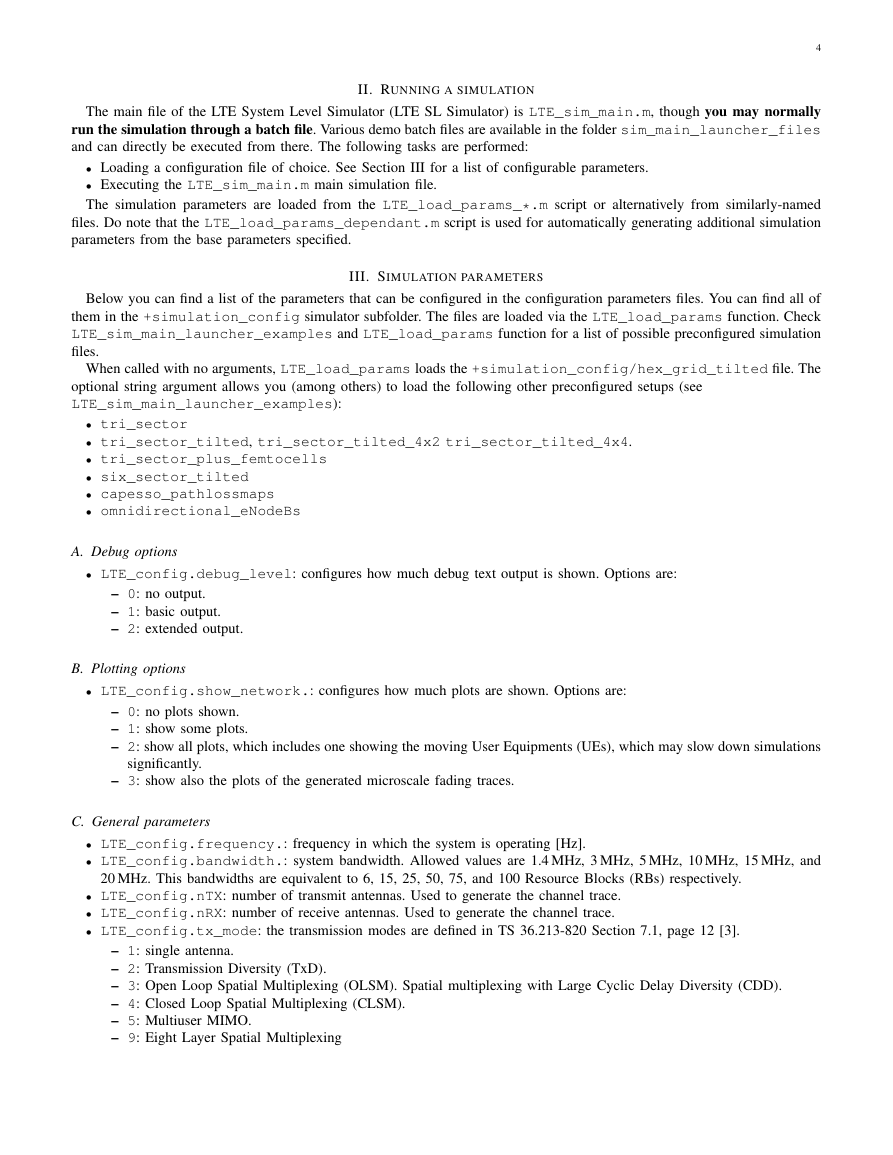
II. RUNNING A SIMULATION
The main file of the LTE System Level Simulator (LTE SL Simulator) is LTE_sim_main.m, though you may normally
run the simulation through a batch file. Various demo batch files are available in the folder sim_main_launcher_files
and can directly be executed from there. The following tasks are performed:
• Loading a configuration file of choice. See Section III for a list of configurable parameters.
• Executing the LTE_sim_main.m main simulation file.
The simulation parameters are loaded from the LTE_load_params_*.m script or alternatively from similarly-named
files. Do note that the LTE_load_params_dependant.m script is used for automatically generating additional simulation
parameters from the base parameters specified.
III. SIMULATION PARAMETERS
Below you can find a list of the parameters that can be configured in the configuration parameters files. You can find all of
them in the +simulation_config simulator subfolder. The files are loaded via the LTE_load_params function. Check
LTE_sim_main_launcher_examples and LTE_load_params function for a list of possible preconfigured simulation
files.
When called with no arguments, LTE_load_params loads the +simulation_config/hex_grid_tilted file. The
optional string argument allows you (among others) to load the following other preconfigured setups (see
LTE_sim_main_launcher_examples):
• tri_sector
• tri_sector_tilted, tri_sector_tilted_4x2 tri_sector_tilted_4x4.
• tri_sector_plus_femtocells
• six_sector_tilted
• capesso_pathlossmaps
• omnidirectional_eNodeBs
A. Debug options
• LTE_config.debug_level: configures how much debug text output is shown. Options are:
– 0: no output.
– 1: basic output.
– 2: extended output.
B. Plotting options
• LTE_config.show_network.: configures how much plots are shown. Options are:
– 0: no plots shown.
– 1: show some plots.
– 2: show all plots, which includes one showing the moving User Equipments (UEs), which may slow down simulations
significantly.
– 3: show also the plots of the generated microscale fading traces.
C. General parameters
• LTE_config.frequency.: frequency in which the system is operating [Hz].
• LTE_config.bandwidth.: system bandwidth. Allowed values are 1.4 MHz, 3 MHz, 5 MHz, 10 MHz, 15 MHz, and
20 MHz. This bandwidths are equivalent to 6, 15, 25, 50, 75, and 100 Resource Blocks (RBs) respectively.
• LTE_config.nTX: number of transmit antennas. Used to generate the channel trace.
• LTE_config.nRX: number of receive antennas. Used to generate the channel trace.
• LTE_config.tx_mode: the transmission modes are defined in TS 36.213-820 Section 7.1, page 12 [3].
– 1: single antenna.
– 2: Transmission Diversity (TxD).
– 3: Open Loop Spatial Multiplexing (OLSM). Spatial multiplexing with Large Cyclic Delay Diversity (CDD).
– 4: Closed Loop Spatial Multiplexing (CLSM).
– 5: Multiuser MIMO.
– 9: Eight Layer Spatial Multiplexing
�
D. Random number generation options
These options allow you to actually reproduce the same exact simulation by means of resetting the random number generator
to a known seed.
5
• LTE_config.seedRandStream: in order to allow repeatability, it is possible to seed MATLAB’s default random
number generator. Set it to either true or false.
• LTE_config.RandStreamSeed: if the above is set to true, it specifies the seed. Seeds must be an integer between
0 and 232 [4].
E. Simulation time
• LTE_config.simulation_time_tti: length of the simulation in Transmission Time Intervals (TTIs).
F. Cache options
• LTE_config.cache_network: whether you want to save the generated eNodeBs, Pathloss map and Shadow fading
map to a .mat file. Either true or false. All cache options work in the following way:
– cache=true and file exists: read cache file.
– cache=true and file does not exist: create and then store data in cache file.
– cache=false: do not use cache at all.
• LTE_config.network_cache: the name of the cache file. set it to auto if you want the simulator to assign a name
• LTE_config.delete_ff_trace_at_end: since the microscala fading trace takes up large amounts of space, when
doing the final save command, it is preferable to delete it, so as not to have too large result files.
• LTE_config.delete_pathloss_at_end: Further reduces the amount of space needed to store the traces by
deleting the pathloss maps from the results file.
• LTE_config.UE_cache: whether to save the user position to a file. Either true or false.
• LTE_config.UE_cache_file: the name of the cache file. set it to auto if you want the simulator to assign a name
automatically.
automatically.
G. Network layout and macroscopic pathloss parameters
These parameters specify how the network layout is created. However, if the map is loaded, these parameters will be
overwritten by the loaded map.
• LTE_config.network_source: Available options
– generated: A hexagonal grid of equidistantly-spaced eNodeB sites with three sectors each will be created.
– capesso: eNodeB position, configuration, and pathloss data are read from data exported from and written from
the CapessoTMplanning tool (see Section XI). When using this source, shadow fading data is not generated, as the
imported pathloss maps should already have it incorporated.
– fixed: Generates N eNodeBs, each with a constant pathloss specified in the LTE_config.pathlosses vector,
containing N values in dB. Useful for comparison with link level results, where a single pathloss value would be
desired for all of the UEs.
1) Generated network parameters:
• LTE_config.network_geometry: Available options
– regular_hexagonal_grid: Regular hexagonal grid with fixed inter-eNodeB distance, as defined in LTE_config.inter_eNodeB_distance
– stochastic: Stochastic eNodeB distribution with spatial density
– hybrid: Hybrid spatial distribution with deterministic- and random parts
– predefined: eNodeB locations as given in LTE_config.eNodeB_positions
The functions are defined in +network_geometry.
• LTE_config.map_resolution: in meters/pixel. Also the resolution used for initial user creation.
• LTE_config.nr_eNodeB_rings: number of eNodeB rings. 0 rings specifies that just a single eNodeB will be created.
• LTE_config.minimum_coupling_loss (optional): describes the minimum loss in signal [dB] between Base Station
(BS) and UE or UE and UE in the worst case and is defined as the minimum distance loss including antenna gains measured
between antenna connectors. Recommended values [5] are 70 dB for urban areas, 80 dB for rural.
• LTE_config.macroscopic_pathloss_model: sets what macroscopic pathloss model is to be used. Depending
on the choice, different choices are available for
LTE_config.macroscopic_pathloss_model_settings.environment. The available macroscopic pathloss
models are:
�
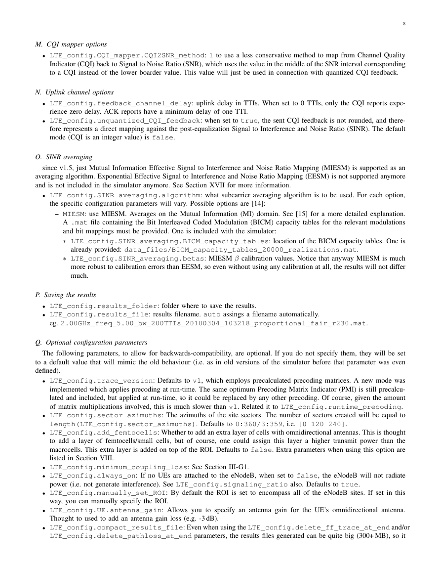
– free space: free space pathloss. More for testing purposes than for actual use with simulations. L = 4πd
6
α. d
λ
in meters. It allows for the following parameters to be specified in
LTE_config.macroscopic_pathloss_model_settings.environment:
∗ α: the α coefficient employed in the pathloss calcualtion.
– cost231: COST231 pathloss model. The possible options for
and COST 231 book.
LTE_config.macroscopic_pathloss_model_settings.environment are:
∗ urban micro: microcell LOS and NLOS pathloss based on the COST231 Walfish-Ikegami model, see TR25.996
∗ urban macro: urban macrocell pathloss based on the COST 231 extended Hata model, see 3GPP TR25.996
∗ suburban macro: suburban macrocell pathloss based on the COST 231 extended Hata model, see 3GPP
and COST 231 book.
TR25.996 and COST 231 book.
– TS36942: see [5] for more information. Possible environments are:
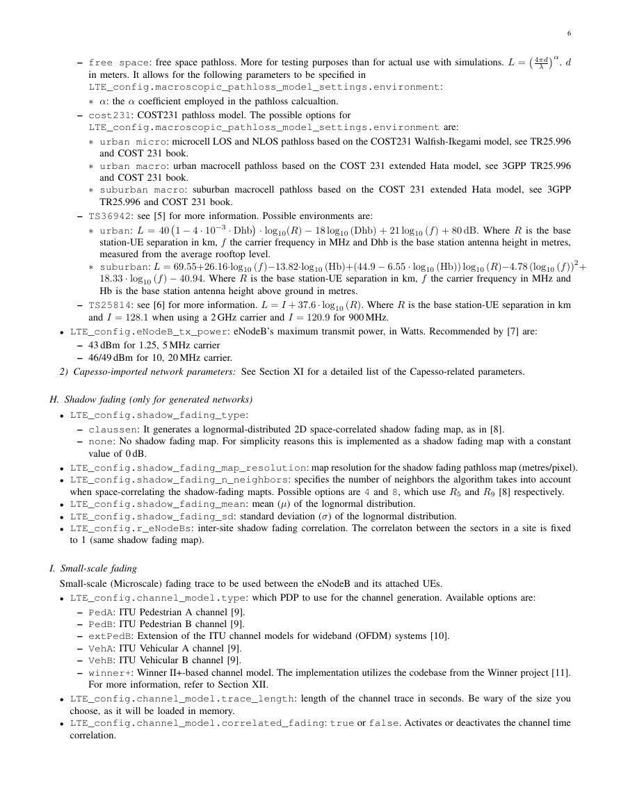
∗ urban: L = 401 − 4 · 10−3 · Dhb · log10(R) − 18 log10 (Dhb) + 21 log10 (f ) + 80 dB. Where R is the base
∗ suburban: L = 69.55+26.16·log10 (f )−13.82·log10 (Hb)+(44.9 − 6.55 · log10 (Hb)) log10 (R)−4.78 (log10 (f ))2+
station-UE separation in km, f the carrier frequency in MHz and Dhb is the base station antenna height in metres,
measured from the average rooftop level.
18.33 · log10 (f ) − 40.94. Where R is the base station-UE separation in km, f the carrier frequency in MHz and
Hb is the base station antenna height above ground in metres.
– TS25814: see [6] for more information. L = I + 37.6 · log10 (R). Where R is the base station-UE separation in km
correlation.
and I = 128.1 when using a 2 GHz carrier and I = 120.9 for 900 MHz.
• LTE_config.eNodeB_tx_power: eNodeB’s maximum transmit power, in Watts. Recommended by [7] are:
– 43 dBm for 1.25, 5 MHz carrier
– 46/49 dBm for 10, 20 MHz carrier.
2) Capesso-imported network parameters: See Section XI for a detailed list of the Capesso-related parameters.
H. Shadow fading (only for generated networks)
• LTE_config.shadow_fading_type:
– claussen: It generates a lognormal-distributed 2D space-correlated shadow fading map, as in [8].
– none: No shadow fading map. For simplicity reasons this is implemented as a shadow fading map with a constant
value of 0 dB.
• LTE_config.shadow_fading_map_resolution: map resolution for the shadow fading pathloss map (metres/pixel).
• LTE_config.shadow_fading_n_neighbors: specifies the number of neighbors the algorithm takes into account
when space-correlating the shadow-fading mapts. Possible options are 4 and 8, which use R5 and R9 [8] respectively.
• LTE_config.shadow_fading_mean: mean (µ) of the lognormal distribution.
• LTE_config.shadow_fading_sd: standard deviation (σ) of the lognormal distribution.
• LTE_config.r_eNodeBs: inter-site shadow fading correlation. The correlaton between the sectors in a site is fixed
to 1 (same shadow fading map).
I. Small-scale fading
Small-scale (Microscale) fading trace to be used between the eNodeB and its attached UEs.
• LTE_config.channel_model.type: which PDP to use for the channel generation. Available options are:
– PedA: ITU Pedestrian A channel [9].
– PedB: ITU Pedestrian B channel [9].
– extPedB: Extension of the ITU channel models for wideband (OFDM) systems [10].
– VehA: ITU Vehicular A channel [9].
– VehB: ITU Vehicular B channel [9].
– winner+: Winner II+-based channel model. The implementation utilizes the codebase from the Winner project [11].
For more information, refer to Section XII.
• LTE_config.channel_model.trace_length: length of the channel trace in seconds. Be wary of the size you
choose, as it will be loaded in memory.
• LTE_config.channel_model.correlated_fading: true or false. Activates or deactivates the channel time
�
7
• LTE_config.pregenerated_ff_file: where to save the channel trace. If the specified file exists, it will be loaded.
For the auto or unexistent filename cases, a new trace will be generated.
e.g. ff_60.0s_2x2_PedB_5.0MHz_5Kmph_20100205_121257.
• LTE_config.recalculate_fast_fading: whether generate the trace even if the file already exists (force a new
trace).
J. UE settings
• LTE_config.UE.receiver_noise_figure: receiver noise figure in dB. Set to 9 dB [5].
• LTE_config.UE.thermal_noise_density: thermal noise density in dBm/Hz.
• LTE_config.UE_distribution: how the UEs are generated over the Region Of Interest (ROI). See Section IX for
a list of the configuration parameters related to each UE distribution.
• LTE_config.UE_speed: speed at which the UEs move. In meters/second.
K. eNodeB settings
• LTE_config.antenna_gain_pattern: gain pattern of the antenna attached to each sector. Only valid for generated
networks. For Capesso-imported networks, these values are not used, as they are read from the cell description files.
Available options are:
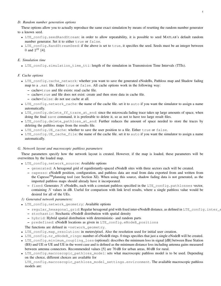
– berger: A(θ) = − min
– TS 36.942: A(θ) = − min
– omnidirectional: A(θ) = 0.
– six-sector: A(θ) = − min
– kathreinTSAntenna: Antenna pattern to be read from an an antenna pattern file. See also Section X It needs of
2
12 θ
2
12 θ
12 θ
2
, −180 ≤ θ ≤ 180 [5].
, −180 ≤ θ ≤ 180.
, −180 ≤ θ ≤ 180.
, 20 dB
35◦
, 23 dB
65◦
, 20 dB
70◦
the following parameters:
∗ LTE_config.site_altiude: Altiude of site (terrain altitude) [m]
∗ LTE_config.site_height: Height of site [m].
∗ LTE_config.rx_height: Receiver height [m].
∗ LTE_config.antenna.mechanical_downtilt: Antenna mechanical downtilt [].
∗ LTE_config.antenna.electrical_downtilt: Antenna electrical downtilt [].
∗ LTE_config.antenna.kathrein_antenna_folder: Folder to scan for the antenna pattern files.
∗ LTE_config.antenna.file_format: either msi or txap, depending on the format of your antenna pattern
∗ LTE_config.antenna.antenna_type: The name of the antenna you want to use. e.g. ’742212’.
∗ LTE_config.antenna.frequency: The frequency at which the pattern should be used [MHz]. It is not
automatically set to the frequency being used because it could happen that all you are interested is the pattern
itself, not whether it would correspond with the actual frequency used.
files.
• LTE_config.max_antenna_gain: antenna gain, in dB. Recommended values are: 15 dBi (rural area 900 MHz, urban
area 2 GHz) and 12 dBi (urban area 900 MHz).
L. Scheduler settings
• LTE_config.scheduler: the type of scheduler to use. Supported schedulers are:
– round robin: equally assigns physical resources to all UEs.
– best cqi: each physical resource (RB) is assigned to the UE with the best channel conditions.
– prop fair Sun: proportional fair scheduler, as in ”Reduced-Complexity Proportional Fair Scheduling for OFDMA
Systems” by Z. Sun, C. Yin, and G. Yue [12].
– FFR: See Section VI.
• LTE_config.latency_time_scale: the simulator keeps track of average UE throughput filtered with an exponential
window. This averaged throughput is basically used by the proportional fair scheduler to obtain the average throughput.
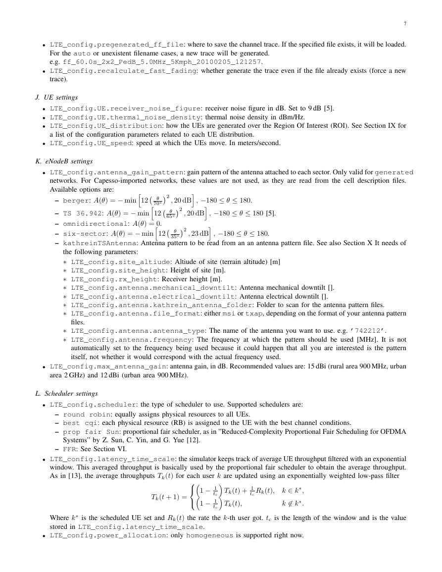
As in [13], the average throughputs Tk(t) for each user k are updated using an exponentially weighted low-pass filter
1 − 1
1 − 1
tc
tc
Tk(t) + 1
tc
Tk(t),
Rk(t), k ∈ k∗,
k ∈ k∗.
Tk(t + 1) =
Where k∗ is the scheduled UE set and Rk(t) the rate the k-th user got. tc is the length of the window and is the value
stored in LTE_config.latency_time_scale.
• LTE_config.power_allocation: only homogeneous is supported right now.
�
M. CQI mapper options
• LTE_config.CQI_mapper.CQI2SNR_method: 1 to use a less conservative method to map from Channel Quality
Indicator (CQI) back to Signal to Noise Ratio (SNR), which uses the value in the middle of the SNR interval corresponding
to a CQI instead of the lower boarder value. This value will just be used in connection with quantized CQI feedback.
N. Uplink channel options
8
• LTE_config.feedback_channel_delay: uplink delay in TTIs. When set to 0 TTIs, only the CQI reports expe-
rience zero delay. ACK reports have a minimum delay of one TTI.
• LTE_config.unquantized_CQI_feedback: when set to true, the sent CQI feedback is not rounded, and there-
fore represents a direct mapping against the post-equalization Signal to Interference and Noise Ratio (SINR). The default
mode (CQI is an integer value) is false.
O. SINR averaging
since v1.5, just Mutual Information Effective Signal to Interference and Noise Ratio Mapping (MIESM) is supported as an
averaging algorithm. Exponential Effective Signal to Interference and Noise Ratio Mapping (EESM) is not supported anymore
and is not included in the simulator anymore. See Section XVII for more information.
• LTE_config.SINR_averaging.algorithm: what subcarrier averaging algorithm is to be used. For each option,
the specific configuration parameters will vary. Possible options are [14]:
– MIESM: use MIESM. Averages on the Mutual Information (MI) domain. See [15] for a more detailed explanation.
A .mat file containing the Bit Interleaved Coded Modulation (BICM) capacity tables for the relevant modulations
and bit mappings must be provided. One is included with the simulator:
∗ LTE_config.SINR_averaging.BICM_capacity_tables: location of the BICM capacity tables. One is
∗ LTE_config.SINR_averaging.betas: MIESM β calibration values. Notice that anyway MIESM is much
more robust to calibration errors than EESM, so even without using any calibration at all, the results will not differ
much.
already provided: data_files/BICM_capacity_tables_20000_realizations.mat.
P. Saving the results
• LTE_config.results_folder: folder where to save the results.
• LTE_config.results_file: results filename. auto assings a filename automatically.
eg. 2.00GHz_freq_5.00_bw_200TTIs_20100304_103218_proportional_fair_r230.mat.
Q. Optional configuration parameters
The following parameters, to allow for backwards-compatibility, are optional. If you do not specify them, they will be set
to a default value that will mimic the old behaviour (i.e. as in old versions of the simulator before that parameter was even
defined).
• LTE_config.trace_version: Defaults to v1, which employs precalculated precoding matrices. A new mode was
implemented which applies precoding at run-time. The same optimum Precoding Matrix Indicator (PMI) is still precalcu-
lated and included, but applied at run-time, so it could be replaced by any other precoding. Of course, given the amount
of matrix multiplications involved, this is much slower than v1. Related it to LTE_config.runtime_precoding.
• LTE_config.sector_azimuths: The azimuths of the site sectors. The number of sectors created will be equal to
length(LTE_config.sector_azimuths). Defaults to 0:360/3:359, i.e. [0 120 240].
• LTE_config.add_femtocells: Whether to add an extra layer of cells with omnidirectional antennas. This is thought
to add a layer of femtocells/small cells, but of course, one could assign this layer a higher transmit power than the
macrocells. This extra layer is added on top of the ROI. Defaults to false. Extra parameters when using this option are
listed in Section VIII.
• LTE_config.minimum_coupling_loss: See Section III-G1.
• LTE_config.always_on: If no UEs are attached to the eNodeB, when set to false, the eNodeB will not radiate
power (i.e. not generate interference). See LTE_config.signaling_ratio also. Defaults to true.
• LTE_config.manually_set_ROI: By default the ROI is set to encompass all of the eNodeB sites. If set in this
way, you can manually specify the ROI.
• LTE_config.UE.antenna_gain: Allows you to specify an antenna gain for the UE’s omnidirectional antenna.
Thought to used to add an antenna gain loss (e.g. -3 dB).
• LTE_config.compact_results_file: Even when using the LTE_config.delete_ff_trace_at_end and/or
LTE_config.delete_pathloss_at_end parameters, the results files generated can be quite big (300+ MB), so it
�


 2023年江西萍乡中考道德与法治真题及答案.doc
 2012年重庆南川中考生物真题及答案.doc
 2013年江西师范大学地理学综合及文艺理论基础考研真题.doc
 2020年四川甘孜小升初语文真题及答案I卷.doc
 2020年注册岩土工程师专业基础考试真题及答案.doc
 2023-2024学年福建省厦门市九年级上学期数学月考试题及答案.doc
 2021-2022学年辽宁省沈阳市大东区九年级上学期语文期末试题及答案.doc
 2022-2023学年北京东城区初三第一学期物理期末试卷及答案.doc
 2018上半年江西教师资格初中地理学科知识与教学能力真题及答案.doc
 2012年河北国家公务员申论考试真题及答案-省级.doc
 2020-2021学年江苏省扬州市江都区邵樊片九年级上学期数学第一次质量检测试题及答案.doc
 2022下半年黑龙江教师资格证中学综合素质真题及答案.doc