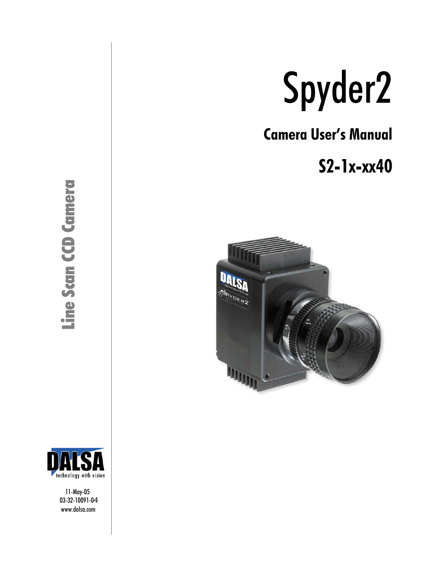
Spyder2
Camera User’s Manual
S2-1x-xx40
a
r
e
m
a
C
D
C
C
n
a
c
S
e
n
i
L
11-May-05
03-32-10091-04
www.dalsa.com
�
2
Spyder2 User’s Manual
© 2005 DALSA. All information provided in this manual is believed to be accurate and reliable. No
responsibility is assumed by DALSA for its use. DALSA reserves the right to make changes to this
information without notice. Reproduction of this manual in whole or in part, by any means, is prohibited
without prior permission having been obtained from DALSA.
About DALSA
DALSA is an international high performance semiconductor and electronics company that designs,
develops, manufactures, and markets digital imaging products and solutions, in addition to providing
wafer foundry services. DALSA’s core competencies are in specialized integrated circuit and electronics
technology, and highly engineered semiconductor wafer processing. Products include image sensor
components; electronic digital cameras; and semiconductor wafer foundry services for use in MEMS,
power semiconductors, image sensors and mixed signal CMOS chips.
DALSA is a public company listed on the Toronto Stock Exchange under the symbol “DSA”. Based in
Waterloo, On. Canada, the company has operations in Bromont, PQ; Colorado Springs, CO; Woodland
Hills, CA; Eindhoven, NL; Munich, Germany and Tokyo, Japan.
All DALSA products are manufactured using the latest state-of-the-art equipment to ensure product
reliability. All electronic modules and cameras are subjected to a 24 hour burn-in test.
For further information not included in this manual, or for information on DALSA’s extensive line of
image sensing products, please call:
DALSA Sales Offices
Waterloo
Europe
Asia Pacific
605 McMurray Rd
Waterloo, ON N2V 2E9
Canada
Tel: 519 886 6000
Fax: 519 886 8023
www.dalsa.com
sales@dalsa.com
Breslauer Str. 34
D-82194 Gröbenzell
(Munich)
Germany
Tel: +49 - 8142 – 46770
Fax: +49 - 8142 – 467746
www.dalsa.com
europe@dalsa.com
Space G1 Building, 4F
2-40-2 Ikebukuro
Toshima-ku, Tokyo 171-0014
Japan
+81 3 5960 6353 (phone)
+81 3 5960 6354 (fax)
www.dalsa.com
asia@dalsa.com
Waterloo
Colorado Springs
Europe
Asia Pacific
DALSA Worldwide Operations
605 McMurray Rd
Waterloo, ON N2V 2E9
Canada
Tel: 519 886 6000
Fax: 519 886 8023
www.dalsa.com
sales@dalsa.com
4820 Centennial Blvd., Suite 115
Colorado Springs, CO 80919
USA
Tel: 719 599 7700
Fax: 719 599 7775
www.dalsa.com
sales.americas@dalsa.com
Breslauer Str. 34
D-82194 Gröbenzell (Munich)
Germany
Tel: +49 - 8142 – 46770
Fax: +49 - 8142 – 467746
www.dalsa.com
europe@dalsa.com
Space G1 Building, 4F
2-40-2 Ikebukuro
Toshima-ku, Tokyo 171-0014
Japan
+81 3 5960 6353 (phone)
+81 3 5960 6354 (fax)
www.dalsa.com
asia@dalsa.com
Camera Link is a trademark registered by PULNiX America Inc., as chair of a committee of industry
members including DALSA.
03-32-10091-04
DALSA
�
Spyder2 User’s Manual
3
Contents
Introduction to the Spyder2 Line Scan Camera ___________________________________ 5
1.1 Camera Highlights.......................................................................................................................................................5
1.2 Image Sensors .............................................................................................................................................................6
1.3 Camera Performance Specifications ............................................................................................................................6
Camera Hardware Interface________________________________________________ 11
2.1 Installation Overview...................................................................................................................................................11
2.2 Input/Output Connectors and LED...............................................................................................................................11
2.3 Timing .........................................................................................................................................................................16
Software Interface: How to Control the Camera __________________________________ 19
3.1 Overview......................................................................................................................................................................19
3.2 Command Format........................................................................................................................................................20
3.3 Processing Chain..........................................................................................................................................................20
3.4 Startup.........................................................................................................................................................................21
3.5 Saving and Restoring Settings.....................................................................................................................................21
3.6 Setting Baud Rate........................................................................................................................................................22
3.7 Setting the Data Mode.................................................................................................................................................22
3.8 Setting the Video Mode ...............................................................................................................................................22
3.9 Setting Line Rate and Exposure Mode.........................................................................................................................23
3.10 Setting a Region of Interest.......................................................................................................................................25
3.11 Returning Video Information ....................................................................................................................................25
3.12 Optimizing Offset Performance.................................................................................................................................27
3.13 Setting Gains .............................................................................................................................................................29
3.14 How to Calibrate the Camera....................................................................................................................................30
3.15 Setting and Reading FPN Coefficients.......................................................................................................................33
3.16 Setting and Reading PRNU Coefficients....................................................................................................................34
3.17 Test Patterns and End of Line Sequence ...................................................................................................................34
3.18 Monitoring the Camera .............................................................................................................................................35
3.19 Rebooting the Camera...............................................................................................................................................37
3.20 Setting the Pre-trigger ..............................................................................................................................................37
Optical, Mechanical, and Thermal Considerations_________________________________ 39
4.1 Mechanical Interface....................................................................................................................................................39
CCD Handling Instructions _________________________________________________ 45
03-32-10091-04
DALSA
�
4
Spyder2 User’s Manual
5.1 Electrostatic Discharge and the CCD Sensor ................................................................................................................45
5.2 Protecting Against Dust, Oil and Scratches..................................................................................................................45
5.3 Cleaning the Sensor Window.......................................................................................................................................46
Troubleshooting ________________________________________________________ 47
6.1 Common Solutions.......................................................................................................................................................47
6.2 Troubleshooting Using the Serial Interface.................................................................................................................48
6.3 Specific Solutions .........................................................................................................................................................50
6.4 Product Support...........................................................................................................................................................52
Camera Link™ Reference _________________________________________________ 53
A1 Camera Link™ Configuration Table............................................................................................................................54
Networking Mode, Error Handling and Command List ______________________________ 57
B1 Networking Mode.........................................................................................................................................................57
B2 Error Handling .............................................................................................................................................................59
B3 Camera Parameter Screen ...........................................................................................................................................63
B4 All Available Commands ..............................................................................................................................................65
EMC Declaration of Conformity______________________________________________ 71
Revision History ________________________________________________________ 73
Index _______________________________________________________________ 75
03-32-10091-04
DALSA
�
5
Spyder2 User’s Manual
1
Introduction to the
Spyder2 Line Scan Camera
1.1 Camera Highlights
Features
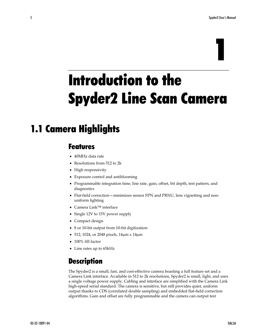
• 40MHz data rate
• Resolutions from 512 to 2k
• High responsivity
• Exposure control and antiblooming
• Programmable integration time, line rate, gain, offset, bit depth, test pattern, and
diagnostics
• Flat-field correction—minimizes sensor FPN and PRNU, lens vignetting and non-
uniform lighting
• Camera Link™ interface
• Single 12V to 15V power supply
• Compact design
• 8 or 10-bit output from 10-bit digitization
• 512, 1024, or 2048 pixels, 14µm x 14µm
• 100% fill factor
• Line rates up to 65kHz
Description
The Spyder2 is a small, fast, and cost-effective camera boasting a full feature set and a
Camera Link interface. Available in 512 to 2k resolutions, Spyder2 is small, light, and uses
a single voltage power supply. Cabling and interface are simplified with the Camera Link
high-speed serial standard. The camera is sensitive, but still provides quiet, uniform
output thanks to CDS (correlated double sampling) and embedded flat-field correction
algorithms. Gain and offset are fully programmable and the camera can output test
03-32-10091-04
DALSA
�
6
Spyder2 User’s Manual
patterns for cable/system troubleshooting. All resolutions provide appropriate, readily-
available standard lens options (C-mount, F-mount, and M42x1 photography standards).
All these features combine to make the Spyder2 an industry leader in power and
affordability.
Applications
The Spyder2 is an ideal choice for these applications:
• Web inspection (multi-cam and narrow web)
• Pick and place
• Document scanning
1.2 Image Sensors
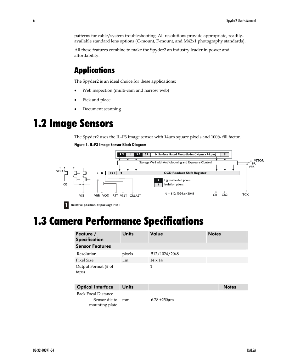
The Spyder2 uses the IL-P3 image sensor with 14µm square pixels and 100% fill factor.
Figure 1. IL-P3 Image Sensor Block Diagram
1
1
Relative position of package Pin 1
1.3 Camera Performance Specifications
Feature /
Specification
Sensor Features
Resolution
Pixel Size
Output Format (# of
taps)
Units
Value
Notes
pixels
µm
512/1024/2048
14 x 14
1
Optical Interface
Back Focal Distance
Sensor die to
mounting plate
Units
mm
6.78 ±250µm
Notes
DALSA
03-32-10091-04
�
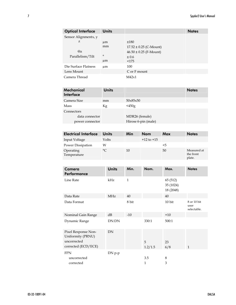
7
Units
µm
mm
°
µm
µm
±180
17.52 ± 0.25 (C-Mount)
46.50 ± 0.25 (F-Mount)
± 0.6
<175
100
C or F mount
M42x1
Units
mm
Kg
50x85x50
<450g
MDR26 (female)
Hirose 6-pin (male)
Optical Interface
Sensor Alignment x, y
z
z
Parallelism/Tilt
Die Surface Flatness
Lens Mount
Camera Thread
Mechanical
Interface
Camera Size
Mass
Connectors
data connector
power connector
Electrical Interface Units
Volts
Input Voltage
Power Dissipation
W
°C
Operating
Temperature
Min
10
Nom
+12 to +15
Max
<5
50
Spyder2 User’s Manual
Notes
Notes
Notes
Measured at
the front
plate.
Units
Min.
Nom.
Max.
Notes
Camera
Performance
Line Rate
kHz
1
Data Rate
Data Format
MHz
40
8 bit
Nominal Gain Range
Dynamic Range
dB
DN:DN
Pixel Response Non-
Uniformity (PRNU)
uncorrected
corrected (ECD/ECE)
FPN
uncorrected
corrected
DN
DN p-p
-10
330:1
5
1.2/1.5
3.5
1
65 (512)
35 (1024)
18 (2048)
40
10 bit
+10
500:1
23
6/8
8
3
8 or 10 bit
user
selectable.
1
03-32-10091-04
DALSA
�
8
Spyder2 User’s Manual
Camera
Performance
Random Noise
DN rms
Units
Min.
Nom.
Max.
Notes
Calibrated DC Offset
DN
Antiblooming
Responsivity
Power Up Duration
SEE
NEE
DN/(nJ/
cm2)
sec
nJ/cm2
pJ/cm2
Regulatory
Regulatory Compliance
Shock and Vibration
CE
MIL-STD-810E
@-10dB gain
@0dB gain
@+10dB gain
@-10dB gain
@0dB gain
@+10dB gain
@-10dB gain
@0dB gain
@+10dB gain
@530nm, 0dB
@530nm, 0dB
0.5
0.75
2.2
13.6±2
42.8±5
136.0±16
1.2
4
3
5
17
100x
15
5.79
37.3
DN = Digital Numbers (0-255); also known as gray levels.
1. ECD= Exposure control disabled. When operating the camera in exposure mode 2
(see section 3.9 Setting Line Rate and Exposure Mode for details), exposure control is
disabled until the set command is sent. All other exposure modes operate with ECE
or exposure control enabled.
Test conditions unless otherwise noted:
• All measurements taken in 8 bit mode
• Data Rate: 40 MHz
• Line Rate: maximum (FPN and PRNU measured at minimum line rate), DC-Offset to
be characterized over different line rates
• Nominal Gain setting, unless specified
• Light Source: Broadband Quartz Halogen, 3250K, with 750nm cutoff filter installed
• Ambient test temperature: 25°C.
• De-rating specifications for temperature range from 0°C to 50°C.
03-32-10091-04
DALSA
�


 2023年江西萍乡中考道德与法治真题及答案.doc
 2012年重庆南川中考生物真题及答案.doc
 2013年江西师范大学地理学综合及文艺理论基础考研真题.doc
 2020年四川甘孜小升初语文真题及答案I卷.doc
 2020年注册岩土工程师专业基础考试真题及答案.doc
 2023-2024学年福建省厦门市九年级上学期数学月考试题及答案.doc
 2021-2022学年辽宁省沈阳市大东区九年级上学期语文期末试题及答案.doc
 2022-2023学年北京东城区初三第一学期物理期末试卷及答案.doc
 2018上半年江西教师资格初中地理学科知识与教学能力真题及答案.doc
 2012年河北国家公务员申论考试真题及答案-省级.doc
 2020-2021学年江苏省扬州市江都区邵樊片九年级上学期数学第一次质量检测试题及答案.doc
 2022下半年黑龙江教师资格证中学综合素质真题及答案.doc