Cortex-M4 Technical Reference Manual
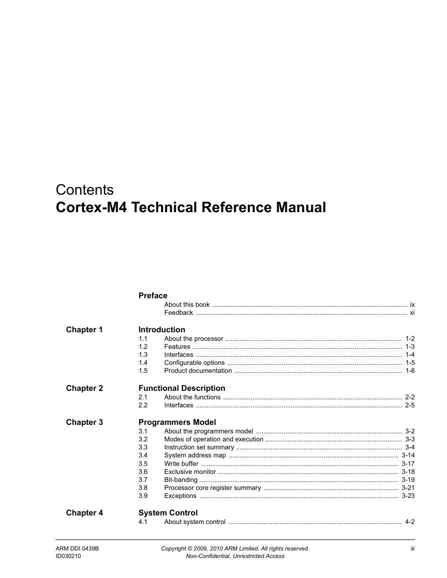
Contents
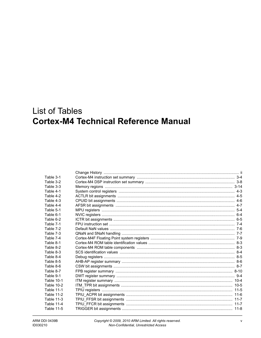
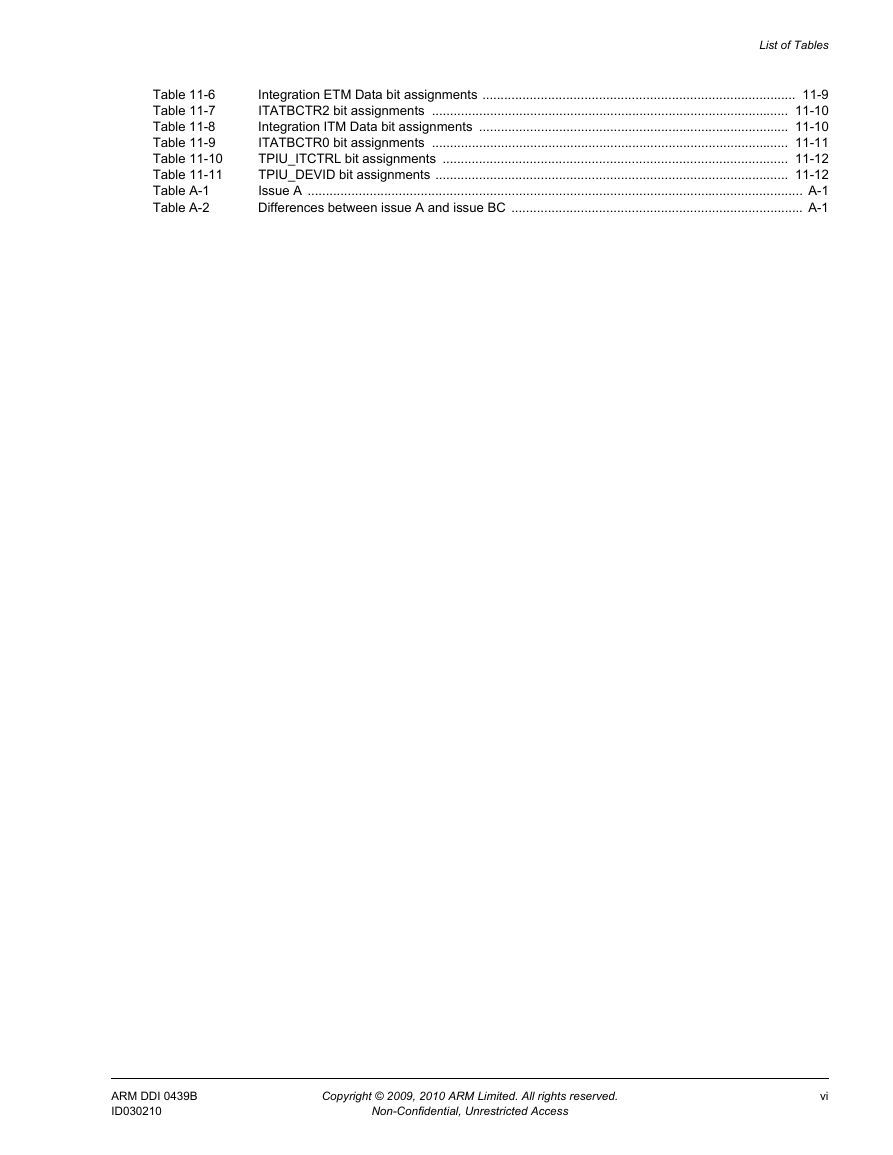
List of Tables
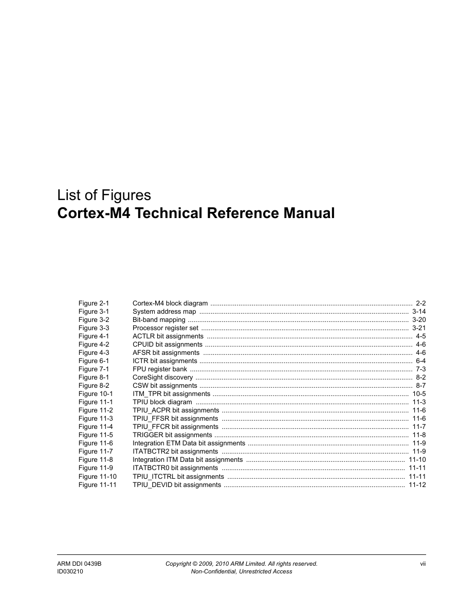
List of Figures
Preface
About this book
Product revision status
Intended audience
Using this book
Conventions
Typographical
Additional reading
ARM publications
Other publications
Feedback
Feedback on this product
Feedback on this manual
Introduction
1.1 About the processor
1.2 Features
1.3 Interfaces
1.4 Configurable options
1.5 Product documentation
1.5.1 Documentation
1.5.2 Design Flow
1.5.3 Architecture and protocol information
ARM architecture
Bus architecture
Debug
Embedded Trace Macrocell
Floating Point Unit
Functional Description
2.1 About the functions
2.2 Interfaces
2.2.1 Bus interfaces
ICode memory interface
DCode memory interface
System interface
Private Peripheral Bus (PPB)
2.2.2 ETM interface
2.2.3 AHB Trace Macrocell interface
2.2.4 Debug port AHB-AP interface
Programmers Model
3.1 About the programmers model
3.2 Modes of operation and execution
3.2.1 Operating modes
3.2.2 Operating states
3.2.3 Privileged access and user access
3.3 Instruction set summary
3.3.1 Cortex-M4 instructions
3.3.2 Load/store timings
3.3.3 Binary compatibility with other Cortex processors
3.4 System address map
3.4.1 Private peripheral bus
3.4.2 Unaligned accesses that cross regions
3.5 Write buffer
3.6 Exclusive monitor
3.7 Bit-banding
3.7.1 Directly accessing an alias region
3.7.2 Directly accessing a bit-band region
3.8 Processor core register summary
3.9 Exceptions
3.9.1 Exception handling
Base register update in LDM and STM operations
System Control
4.1 About system control
4.2 Register summary
4.3 Register descriptions
4.3.1 Auxiliary Control Register, ACTLR
4.3.2 CPUID Base Register, CPUID
4.3.3 Auxiliary Fault Status Register, AFSR
Memory Protection Unit
5.1 About the MPU
5.2 MPU functional description
5.3 MPU programmers model
Nested Vectored Interrupt Controller
6.1 About the NVIC
6.2 NVIC functional description
6.2.1 Low power modes
6.2.2 Level versus pulse interrupts
6.3 NVIC programmers model
6.3.1 Interrupt Controller Type Register, ICTR
Floating Point Unit
7.1 About the FPU
7.2 FPU Functional Description
7.2.1 FPU views of the register bank
7.2.2 Modes of operation
Full-compliance mode
Flush-to-zero mode
Default NaN mode
7.2.3 FPU instruction set
7.2.4 Compliance with the IEEE 754 standard
7.2.5 Complete implementation of the IEEE 754 standard
7.2.6 IEEE 754 standard implementation choices
NaN handling
Comparisons
Underflow
7.2.7 Exceptions
7.3 FPU Programmers Model
7.3.1 Enabling the FPU
Debug
8.1 About debug
8.1.1 Cortex-M4 ROM table identification and entries
8.1.2 System Control Space
SCS CoreSight identification
8.1.3 Debug register summary
8.2 About the AHB-AP
8.2.1 AHB-AP transaction types
8.2.2 AHB-AP programmers model
AHB-AP Control and Status Word Register, CSW
8.3 About the Flash Patch and Breakpoint Unit (FPB)
8.3.1 FPB functional description
8.3.2 FPB programmers model
Data Watchpoint and Trace Unit
9.1 About the DWT
9.2 DWT functional description
9.3 DWT Programmers Model
Instrumentation Trace Macrocell Unit
10.1 About the ITM
10.2 ITM functional description
10.3 ITM programmers model
10.3.1 ITM Trace Privilege Register, ITM_TPR
Trace Port Interface Unit
11.1 About the Cortex-M4 TPIU
11.2 TPIU functional description
11.2.1 TPIU block diagrams
11.2.2 TPIU Formatter
11.2.3 Serial Wire Output format
11.3 TPIU programmers model
11.3.1 Asynchronous Clock Prescaler Register, TPIU_ACPR
11.3.2 Formatter and Flush Status Register, TPIU_FFSR
11.3.3 Formatter and Flush Control Register, TPIU_FFCR
11.3.4 TRIGGER
11.3.5 Integration ETM Data
11.3.6 ITATBCTR2
11.3.7 Integration ITM Data
11.3.8 ITATBCTR0
11.3.9 Integration Mode Control, TPIU_ITCTRL
11.3.10 TPIU_DEVID
Revisions
Glossary



 2023年江西萍乡中考道德与法治真题及答案.doc
 2012年重庆南川中考生物真题及答案.doc
 2013年江西师范大学地理学综合及文艺理论基础考研真题.doc
 2020年四川甘孜小升初语文真题及答案I卷.doc
 2020年注册岩土工程师专业基础考试真题及答案.doc
 2023-2024学年福建省厦门市九年级上学期数学月考试题及答案.doc
 2021-2022学年辽宁省沈阳市大东区九年级上学期语文期末试题及答案.doc
 2022-2023学年北京东城区初三第一学期物理期末试卷及答案.doc
 2018上半年江西教师资格初中地理学科知识与教学能力真题及答案.doc
 2012年河北国家公务员申论考试真题及答案-省级.doc
 2020-2021学年江苏省扬州市江都区邵樊片九年级上学期数学第一次质量检测试题及答案.doc
 2022下半年黑龙江教师资格证中学综合素质真题及答案.doc