Lontium Semiconductor
LT6911C Datasheet R1.2
LONTIUM SEMICONDUCTOR
CORPORATION
ClearEdge Technology
HDMI1.4 to Dual-port MIPI DSI/CSI with Audio
LT6911C
Datasheet
Confidential
We produce mixed-signal products for a better digital world!
1
�
Lontium Semiconductor
1. Features
HDMI1.4 Receiver
Compliant with the HDMI 1.4 specification with TMDS data
LT6911C Datasheet R1.2
Support 100KHz and 400KHz I2C slave
Power from phone or adapter mode selection
Integrated Microprocessor
Embedded EDID shadow.
Temperature Range: -40°C ~ +85°C
ESD 4kV HBM
rates up to 3.4Gbps per channel
Support HDCP 1.4
Adaptive receiver Equalization
connector losses
for PCB, cable and
2. Description
Single/Dual-Port MIPI® DSI/CSI Transmitter
Compliant with DCS1.02, D-PHY1.2& DSI1.02 &CSI-2 1.0
1 Clock Lane, and 1~4 Configurable Data Lanes per port
1/2 configurable port
80Mb/s~1.5Gb/s per Data Lane
Data Lane and Polarity Swapping
Maximum 64Pixels overlap for each half
Burst Mode and Command ModeSupported
Support RGB666, Loosely RGB666, RGB888,
RGB565, 16-bit YCbCr4:2:2,20-bit YCbCr4:2:2,24-bit
YCbCr 4:2:2, 12-bit YCbCr4:2:0Video Format
Video stream copy mode for each single/dual-port
Side-by-side 3D support
Port swap
Miscellaneous
3.3V/1.2VSupply Power
Internal CSC support conversions between YCbCr 4:4:4
and RGB, and between YCbCr 4:2:2 andYCbCr 4:4:4
Support SPDIF and 2-channel IIS audio output
is a high performance HDMI1.4
The LT6911C
to
MIPI®DSI/CSI chip for VR/Smart phone/Display application.
For MIPI®DSI/CSI output, LT6911C features configurable
single-port or dual-port MIPI®DSI/CSI with 1 high-speed
clock lane and 1~4 high-speed data lanes operating at
maximum 1.5Gb/s/lane, which can support a total bandwidth
of up to 12Gbps. LT6911C supports Burst mode DSI video
data transferring, also support flexible video data mapping
path.
For 2D video stream, the same video stream can be
mapped to two separated panel, for 3D video format, left
side data can be sent to one panel, and right side data can
be sent to another panel.
3. Applications
Mobile system
Display
VR
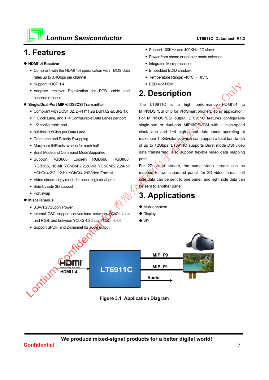
HDMI1.4
LT6911C
MIPI P0
MIPI P1
Audio
Figure 3.1 Application Diagram
Confidential
We produce mixed-signal products for a better digital world!
2
�
Lontium Semiconductor
4. Ordering Information
LT6911C Datasheet R1.2
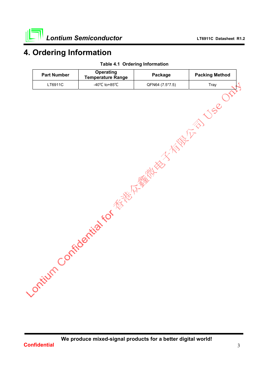
Table 4.1 Ordering Information
Part Number
Operating
Temperature Range
Package
Packing Method
LT6911C
-40℃ to+85℃
QFN64 (7.5*7.5)
Tray
Confidential
We produce mixed-signal products for a better digital world!
3
�
Lontium Semiconductor
LT6911C Datasheet R1.2
Table of Contents
1. Features ................................................................................................................................ 2
2. Description ........................................................................................................................... 2
3. Applications ......................................................................................................................... 2
4. Ordering Information ........................................................................................................... 3
5. Revision History .................................................................................................................. 5
6. Pinning Information ............................................................................................................. 6
6.1 Pin Configuration.............................................................................................................. 6
6.2 Pin Description ................................................................................................................. 7
7. Function Description ........................................................................................................... 9
7.1 Function Block Diagram ................................................................................................... 9
8. Specification ...................................................................................................................... 10
8.1 Absolute Maximum Conditions ....................................................................................... 10
8.2 Normal Operating Conditions ......................................................................................... 10
8.3 DC Characteristics ......................................................................................................... 10
8.4 AC Characteristics ......................................................................................................... 11
8.5 Power Consumption ....................................................................................................... 12
8.6 Power-up and Reset Sequence ..................................................................................... 12
9. Package Information ......................................................................................................... 13
Confidential
We produce mixed-signal products for a better digital world!
4
�
Lontium Semiconductor
LT6911C Datasheet R1.2
Version
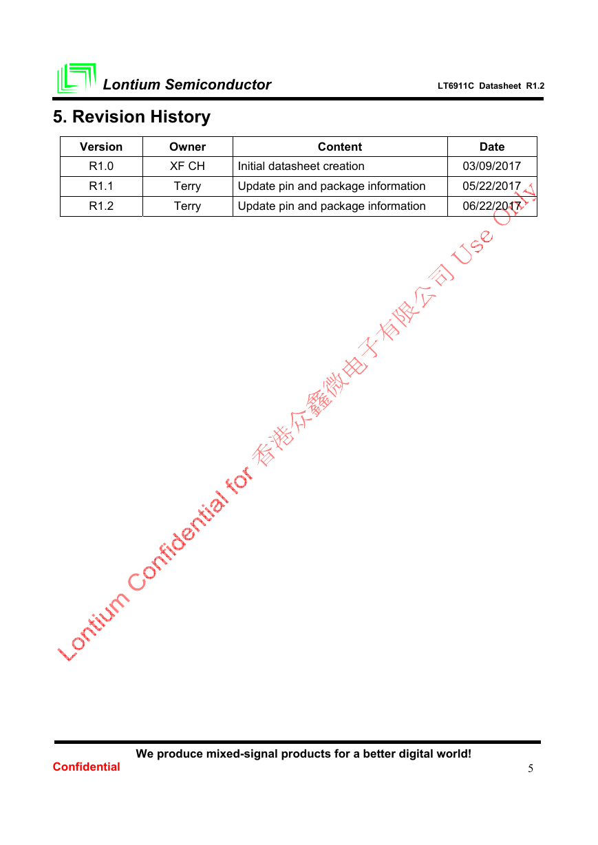
5. Revision History
Owner
XF CH
Terry
Terry
R1.0
R1.1
R1.2
Content
Initial datasheet creation
Update pin and package information
Update pin and package information
Date
03/09/2017
05/22/2017
06/22/2017
Confidential
We produce mixed-signal products for a better digital world!
5
�
Lontium Semiconductor
6. Pinning Information
6.1 Pin Configuration
To improve signal integrity, all differential pairs should be routed with 100Ω±10% differential impedance.Maximum trace length
mismatch should be less than 5mil and keep total trace length to a minimum for all differential traces. Routing differential pairs
on the top or bottom layer with no vias as on signal path is highly recommended.
LT6911C Datasheet R1.2
Figure 6.1.1 LT6911C Pin Assignment (Top View)
To minimize the power supply noise floor, at least one 0.1μF and one 0.01μF decoupling capacitors recommended to be
installed near all the LT6911C power pins. To avoid large current loops and trace inductance, thetrace length between
decoupling capacitor and device power inputs pins must be minimized.
Confidential
We produce mixed-signal products for a better digital world!
6
�
Lontium Semiconductor
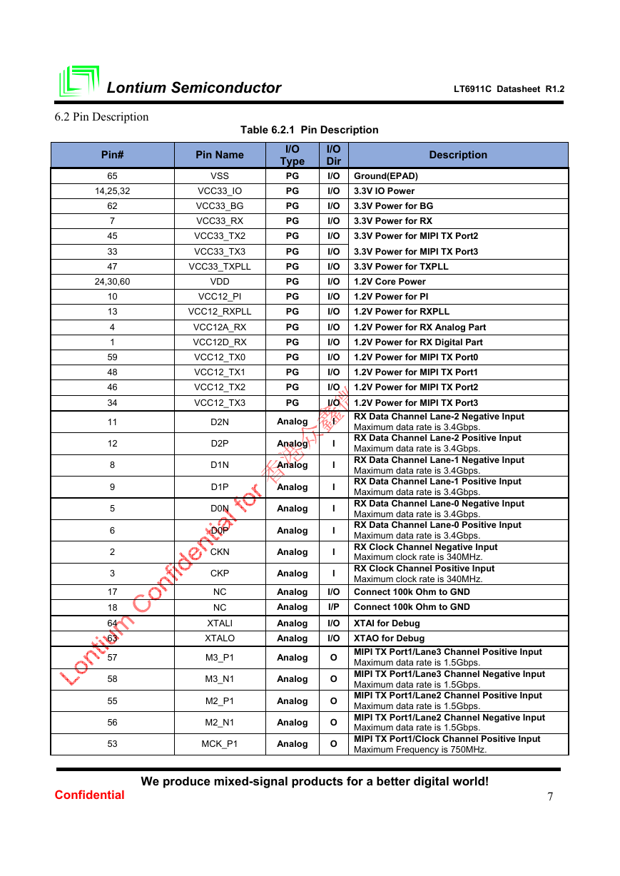
6.2 Pin Description
Table 6.2.1 Pin Description
LT6911C Datasheet R1.2
Pin#
65
14,25,32
62
7
45
33
47
24,30,60
10
13
4
1
59
48
46
34
11
12
8
9
5
6
2
3
17
18
64
63
57
58
55
56
53
Pin Name
VSS
VCC33_IO
VCC33_BG
VCC33_RX
VCC33_TX2
VCC33_TX3
VCC33_TXPLL
VDD
VCC12_PI
VCC12_RXPLL
VCC12A_RX
VCC12D_RX
VCC12_TX0
VCC12_TX1
VCC12_TX2
VCC12_TX3
D2N
D2P
D1N
D1P
D0N
D0P
CKN
CKP
NC
NC
XTALI
XTALO
M3_P1
M3_N1
M2_P1
M2_N1
MCK_P1
I/O
Type
PG
PG
PG
PG
PG
PG
PG
PG
PG
PG
PG
PG
PG
PG
PG
PG
Analog
Analog
Analog
Analog
Analog
Analog
Analog
Analog
Analog
Analog
Analog
Analog
Analog
Analog
Analog
Analog
Analog
Description
I/O
Dir
I/O Ground(EPAD)
I/O 3.3V IO Power
I/O 3.3V Power for BG
I/O 3.3V Power for RX
I/O 3.3V Power for MIPI TX Port2
I/O 3.3V Power for MIPI TX Port3
I/O 3.3V Power for TXPLL
I/O 1.2V Core Power
I/O 1.2V Power for PI
I/O 1.2V Power for RXPLL
I/O 1.2V Power for RX Analog Part
I/O 1.2V Power for RX Digital Part
I/O 1.2V Power for MIPI TX Port0
I/O 1.2V Power for MIPI TX Port1
I/O 1.2V Power for MIPI TX Port2
I/O 1.2V Power for MIPI TX Port3
I
I
I
I
I
I
I
RX Data Channel Lane-2 Negative Input
Maximum data rate is 3.4Gbps.
RX Data Channel Lane-2 Positive Input
Maximum data rate is 3.4Gbps.
RX Data Channel Lane-1 Negative Input
Maximum data rate is 3.4Gbps.
RX Data Channel Lane-1 Positive Input
Maximum data rate is 3.4Gbps.
RX Data Channel Lane-0 Negative Input
Maximum data rate is 3.4Gbps.
RX Data Channel Lane-0 Positive Input
Maximum data rate is 3.4Gbps.
RX Clock Channel Negative Input
Maximum clock rate is 340MHz.
RX Clock Channel Positive Input
Maximum clock rate is 340MHz.
I
I/O Connect 100k Ohm to GND
I/P
Connect 100k Ohm to GND
I/O XTAI for Debug
I/O XTAO for Debug
O MIPI TX Port1/Lane3 Channel Positive Input
O MIPI TX Port1/Lane3 Channel Negative Input
O MIPI TX Port1/Lane2 Channel Positive Input
O MIPI TX Port1/Lane2 Channel Negative Input
O MIPI TX Port1/Clock Channel Positive Input
Maximum data rate is 1.5Gbps.
Maximum data rate is 1.5Gbps.
Maximum data rate is 1.5Gbps.
Maximum data rate is 1.5Gbps.
Maximum Frequency is 750MHz.
Confidential
We produce mixed-signal products for a better digital world!
7
�
Lontium Semiconductor
LT6911C Datasheet R1.2
Pin#
54
51
52
49
50
43
44
41
42
39
40
37
38
35
36
15
16
23
28
31
26
27
20
29
19
22
21
61
Pin Name
MCK_N1
M1_P1
M1_N1
M0_P1
M0_N1
M3_P3
M3_N3
M2_P3
M2_N3
MCK_P3
MCK_N3
M1_P3
M1_N3
M0_P3
M0_N3
DSDA
DSCL
RX_HPD
IIS_SCLK
IIS_D0/SPDIF
GPIO5
IIS_WS
RSTN
IIS_MCLK
SLEEP_33
CSDA
CSCL
REXT
I/O
Type
Analog
Analog
Analog
Analog
Analog
Analog
Analog
Analog
Analog
Analog
Analog
Analog
Analog
Analog
Analog
Schmitt,
Schmitt,
OD
OD
OD
LVTTL
LVTTL
LVTTL
LVTTL
Schmitt
LVTTL
Schmitt
Schmitt,
Schmitt,
OD
OD
Analog
Maximum data rate is 1.5Gbps.
Maximum data rate is 1.5Gbps.
Description
Maximum data rate is 1.5Gbps.
Maximum data rate is 1.5Gbps.
Maximum data rate is 1.5Gbps.
Maximum data rate is 1.5Gbps.
Maximum Frequency is 750MHz.
I/O
Dir
O MIPI TX Port1/Clock Channel Negative Input
O MIPI TX Port1/Lane1 Channel Positive Input
O MIPI TX Port1/Lane1 Channel Negative Input
O MIPI TX Port1/Lane0 Channel Positive Input
O MIPI TX Port1/Lane0 Channel Negative Input
O MIPI TX Port3/Lane3 Channel Positive Input
O MIPI TX Port3/Lane3 Channel Negative Input
O MIPI TX Port3/Lane2 Channel Positive Input
O MIPI TX Port3/Lane2 Channel Negative Input
O MIPI TX Port3/Clock Channel Positive Input
O MIPI TX Port3/Clock Channel Negative Input
O MIPI TX Port3/Lane1 Channel Positive Input
O MIPI TX Port3/Lane1 Channel Negative Input
O MIPI TX Port3/Lane0 Channel Positive Input
O MIPI TX Port3/Lane0 Channel Negative Input
Maximum Frequency is 750MHz.
Maximum Frequency is 750MHz.
Maximum data rate is 1.5Gbps.
Maximum data rate is 1.5Gbps.
Maximum data rate is 1.5Gbps.
Maximum data rate is 1.5Gbps.
Maximum data rate is 1.5Gbps.
Maximum data rate is 1.5Gbps.
I/O Slave I2C SDA Signal For EDID
Slave I2C SCL Signal For EDID
Hot Plug Signal
I
O
I/O SCLK of IIS
I/O D0/SPDIF of IIS
I/O GPIO
I/O WS of IIS
I
I/O MCLK of IIS
I
External Reset Signal, Low is Reset.
External Sleep Mode Control Signal
I/O Slave I2C SDA Signal For Program Register
I
O
Slave I2C SCL Signal For Program Register
External 7.68Kohm Resistor For BG
Confidential
We produce mixed-signal products for a better digital world!
8
�




 2023年江西萍乡中考道德与法治真题及答案.doc
 2012年重庆南川中考生物真题及答案.doc
 2013年江西师范大学地理学综合及文艺理论基础考研真题.doc
 2020年四川甘孜小升初语文真题及答案I卷.doc
 2020年注册岩土工程师专业基础考试真题及答案.doc
 2023-2024学年福建省厦门市九年级上学期数学月考试题及答案.doc
 2021-2022学年辽宁省沈阳市大东区九年级上学期语文期末试题及答案.doc
 2022-2023学年北京东城区初三第一学期物理期末试卷及答案.doc
 2018上半年江西教师资格初中地理学科知识与教学能力真题及答案.doc
 2012年河北国家公务员申论考试真题及答案-省级.doc
 2020-2021学年江苏省扬州市江都区邵樊片九年级上学期数学第一次质量检测试题及答案.doc
 2022下半年黑龙江教师资格证中学综合素质真题及答案.doc