http://www.paper.edu.cn
基于预测校正算法的火星进入段制导
周鎏宇1,夏元清1,陈荣芳1,崔平远2
1 北京理工大学,自动化学院,北京,100081
2 北京理工大学,宇航学院,北京,100081
摘要:这篇文章介绍了基于预测校正算法的火星进入段制导方法的发展并对其进行评估。未来
火星任务的要求是能确保精确和高海拔的火星表面着陆。现在主要有两种进入段制导算法:基
于标称轨迹的制导和基于预测校正的制导。跟踪标称轨迹的制导算法相对不依赖于模型,并且
不要求很高的在线计算能力。但是它对初始条件具有较高的敏感性。而预测校正算法对于初始
扰动的敏感性较低,但是却要求较高的在线计算能力。这篇文章对预测校正,横向控制和航向
调整算法给出了详细介绍,同时提出了一种改进的预测校正算法来减少在线计算量。仿真结果
表明这种进入段制导算法在有很高不确定性的情况下仍然能体现出可靠性和鲁棒性。
关键词:进入制导,预测校正,在线计算,横向控制,航向调整。
中图分类号: TP1
Mars Entry Guidance Based on
Predictor-Corrector Algorithm
ZHOU Liuyu1, XIA Yuanqing1,CHEN Rongfang1,CUI Pingyuan2
1 School of Automation, Beijing Institute of Technology, Beijing 100081, China
2 School of Aeronautics, Beijing Institute of Technology, Beijing 100081, China
Abstract: This paper addresses the development and evaluation of the numerical
predictor-corrector algorithm for the Mars entry guidance. The requirement of future Mars
missions is to enable pinpoint and high elevation Mars landing. There are two main entry
guidance algorithms: guidance using a reference trajectory and guidance using
predictor-corrector. Guidance algorithm that tracks the reference trajectory during entry, has
some degree of model-independence and does not require fast on-board computation, but it is
sensitive to initial conditions. However, the predictor-corrector algorithm can be less sensitive
基金项目: The work of Yuanqing Xia was supported by the National Basic Research Program of China (973
Program) (2012CB720000), the National Natural Science Foundation of China (61225015,60974011), the Ph.D.
Programs Foundation of Ministry of Education of China (20091101110023, 20111101110012), and Beijing Municipal
Natural Science Foundation (4102053,4101001).
作 者 简 介: Zhou Liuyu (1991-) male, bachelor candidate, major research direction: guidance and control,
predictor-corrector. E-mail:liuyuzhou1@gmail.com. Correspondence author: Xia Yuanqing (1971-) male, professor,
major research direction: spacecraft system control, networked control systems, robust control, active disturbance re-
jection control. E-mail:xia yuanqing@bit.edu.cn. Chen Rongfang (1988-) male, master candidate, major research di-
rection: guidance and control system design for the precise landing of the Mars lander. E-mail:xiaxiao432@gmail.com.
Cui Pingyuan (1961-) male, professor, major research direction: deep space detector autonomous technology and
track design, aircraft ight dynamics and control, intelligent information processing and autonomous navigation.
E-mail:cuipy@bit.edu.cn.
- 1 -
�
http://www.paper.edu.cn
to initial dispersions, but needs fast on-board computation. Detailed descriptions of
predictor-corrector algorithm, lateral control logic and heading alignment are given and an
improved predictor-corrector algorithm is provided to shorten the on-board computational
time. Simulation results show that this entry guidance algorithm demonstrates reliable and
robust performance in situations with high uncertainties.
Key words: entry guidance, predictor-corrector, on-board computation, lateral control,
heading alignment.
0 Introduction
The entry guidance purpose is to deliver the lander to a desired parachute deployment point
in three-dimensional position space (longitude, latitude and altitude). Many considerable efforts
of entry guidance had been made. Harpold J. C. and Graves C. A. [1] carried out a shuttle
entry guidance based on the drag-to-velocity profile. Lu P. presented a quasi-equilibrium Glide
guidance in lifting entry flight [2]. A.Saraf et. al [3] presented an entry guidance algorithm
called evolved acceleration guidance logic for entry (EAGLE) with potential to reduce the
amount of pre-mission design effort.
The main challenge of Martian entry, however, is Mars’ comparatively thin atmosphere
[4]. The Martian atmosphere is approximately 100 times thinner than that on Earth, which
is insufficient to provide adequate deceleration at high altitudes. Under these conditions the
vehicle’s control authority will be low. Entry guidance algorithms to be used on Mars have to
account for the reduced control authority to ensure satisfactory delivery accuracy. Carman et
al. [5] and Mendeck and Carman [6] presented a reference-path entry guidance method using
the guidance technique of Apollo second entry phase adapted for Mars landing conditions.
Kluever [7] carried out the comparative performance analysis of pre-planned reference-path and
predictive path-planning entry guidance methods for a lander modelled on the Mars Science
Laboratory(MSL) mission. Powell [8] evaluated the performance of the numerical predictor-
corrector technique to guide a Mars lander to both the aerocapture objective and precision
landing one, namely, to deploy a parachute within 10km of a target. Xia Y., and Fu M. [9]
developed methodology combined of the active disturbance rejection control (ADRC) and slide
mode control(SMC) methods, which can be used as the feedback control laws in Mars entry
guidance which have shown better performances than the traditional proportional-integral-
derivative (PID) law.
This paper describes guidance algorithms that use numerical predictor-corrector techniques
to guide the spacecraft to the proper objectives, which is a modification of the skip entry
guidance for lunar-return mission carried out by Christopher W. Brunner and Ping Lu [10].
The main advantage of predictor-corrector guidance is that it can always ensure a feasible
- 2 -
�
http://www.paper.edu.cn
trajectory that satisfies the required conditions from the current position to the target deploy
site and find suitable command bank angles to fly. However, this advantage is undermined by
the increased computational time of integration and iteration. The total number of lines of code
is much greater than that of other guidance algorithms. So, an improved predictor-corrector
algorithm is provided in this paper to shorten the on-board computational time.
This paper is organized as follows. The entry dynamic problem is formulated in Section 2.
The predictor-corrector algorithm is presented in Section 3. Lateral control logic is analyzed in
Section 4. Section 5 presents heading alignment algorithm. An improved predictor-corrector
algorithm is provided in Section 6. Section 7 gives simulation results and some discussions.
Finally, some concluding remarks are given in Section 8.
1 Entry Dynamic
Since entry duration is short and the vehicle is unpowered during the entry phase, the
lander is modeled as a point mass flying in a planet-fixed coordinate frame. Without taking
into account of the Mars’ rotation, the standard simplified equations of motion for entry are
[11]
˙θ =
˙ϕ =
V
r
V
r
cos γ cos ψ
cos ϕ
cos γ sin ψ
˙r = V sin γ
˙V = −D − g sin γ
[
[
L cos σ − (g − V 2
r
1
V
˙γ =
˙ψ = − 1
]
) cos γ
L sin σ +
V cos γ
V 2
r
cos2 γ cos ψ tan ϕ
(1)
(2)
(3)
(4)
(5)
(6)
]
where θ is the longitude, ϕ is the latitude, r is the radial distance from center of the Mars. V
is the velocity and γ is the flight path angle. ψ is the heading angle which is the angle between
the projection of the velocity on the horizontal plane and the East direction, following the
counter-clockwise (ccw) from East convention (hence Eastward direction is ψ = 0 , Northward
direction is ψ = +90 deg and Southward direction is ψ = −90 deg ) [11]. The angles γ and
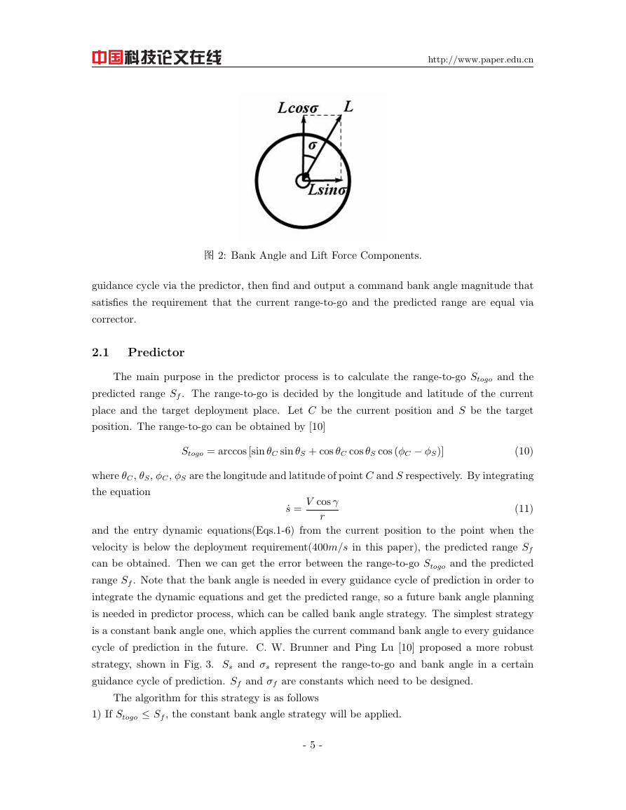
ψ completely define the orientation of the velocity vector. σ is the bank angle defined as the
angle from the vertical direction to the lift vector, such that a bank to the right is positive and
zero bank corresponds to the lift vector directed upward in the longitudinal plane.
The gravitational acceleration is modeled as g = µ/r2, where µ is the planet’s gravitational
constant. In Mars, µ is approximated to 4.284e + 013. The aerodynamic forces acting on the
vehicle can be decomposed into lift and drag. The lift and drag accelerations can be obtained
- 3 -
�
http://www.paper.edu.cn
by
D =
L =
1
2
1
2
ρV 2 S
m
ρV 2 S
m
CD
CL
(7)
(8)
where ρ is the atmospheric density, S stands for the vehicle reference surface area and m is
the mass of the lander. CD and CL represent the drag and lift coefficients, respectively. The
aerodynamic coefficients are typically function of the Mach number and the angle of attack. In
this paper, an exponential function of the atmospheric density profile is obtained as follow
ρ = ρ0 exp
rr0
hs
(9)
where ρ0 is the density at the reference radius r0 and hs is the constant scale height.
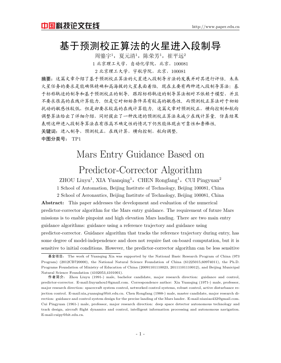
The entry capsule and aerodynamic forces are shown in Fig. 1, where CM represents the
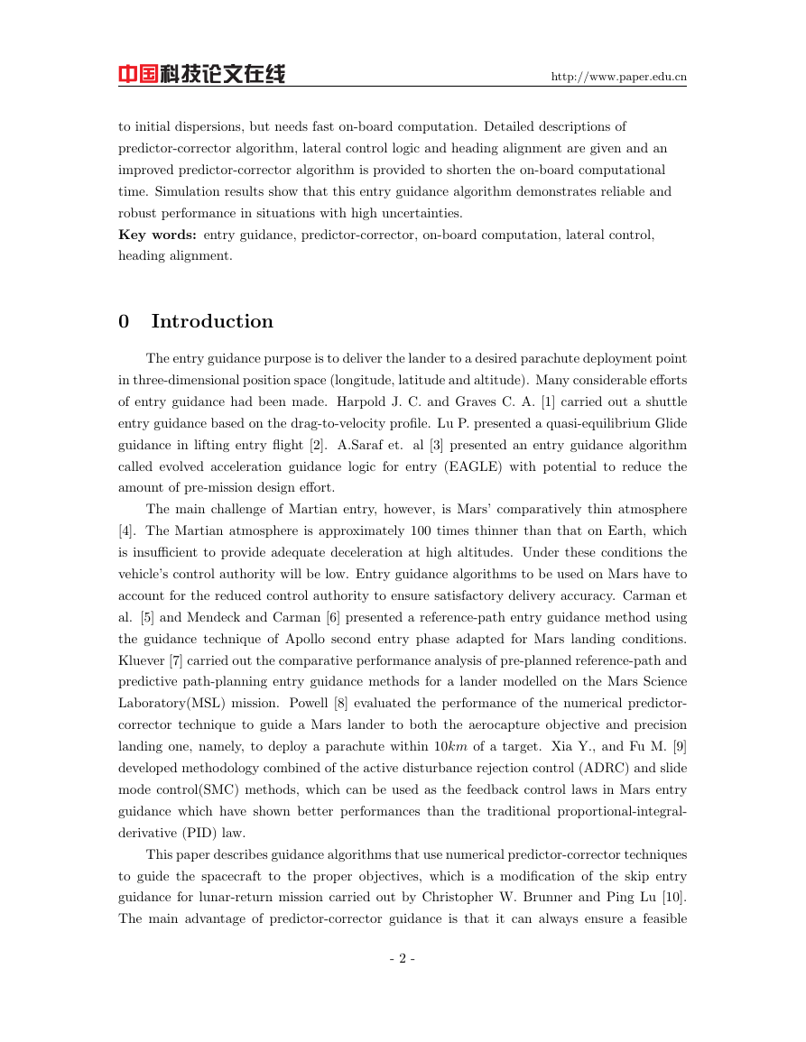
center of mass. The bank angle and lift force components are shown in Fig. 2.
图 1: Entry Capsule and Aerodynamic Forces.
2 Predictor-Corrector Algorithm
The predictor-corrector algorithm discussed here is a downrange predictor-corrector one,
which consists of predictor part and corrector part. Apollo also uses a predictor-corrector
approach, but it is for lateral control. The predicted crossrange miss is compared to the
estimated lateral control capability, and a reversal is performed when the predicted miss is
equal to half of the lateral control capability. In this paper another lateral control logic will be
discussed later. The function of predictor-corrector algorithm is to calculate the error between
the current range-to-go and the predicted range which is also called miss distance in every
- 4 -
�
http://www.paper.edu.cn
图 2: Bank Angle and Lift Force Components.
guidance cycle via the predictor, then find and output a command bank angle magnitude that
satisfies the requirement that the current range-to-go and the predicted range are equal via
corrector.
2.1 Predictor
The main purpose in the predictor process is to calculate the range-to-go Stogo and the
predicted range Sf . The range-to-go is decided by the longitude and latitude of the current
place and the target deployment place. Let C be the current position and S be the target
position. The range-to-go can be obtained by [10]
Stogo = arccos [sin θC sin θS + cos θC cos θS cos (ϕC − ϕS)]
(10)
where θC, θS, ϕC, ϕS are the longitude and latitude of point C and S respectively. By integrating
the equation
˙s =
(11)
V cos γ
r
and the entry dynamic equations(Eqs.1-6) from the current position to the point when the
velocity is below the deployment requirement(400m/s in this paper), the predicted range Sf
can be obtained. Then we can get the error between the range-to-go Stogo and the predicted
range Sf . Note that the bank angle is needed in every guidance cycle of prediction in order to
integrate the dynamic equations and get the predicted range, so a future bank angle planning
is needed in predictor process, which can be called bank angle strategy. The simplest strategy
is a constant bank angle one, which applies the current command bank angle to every guidance
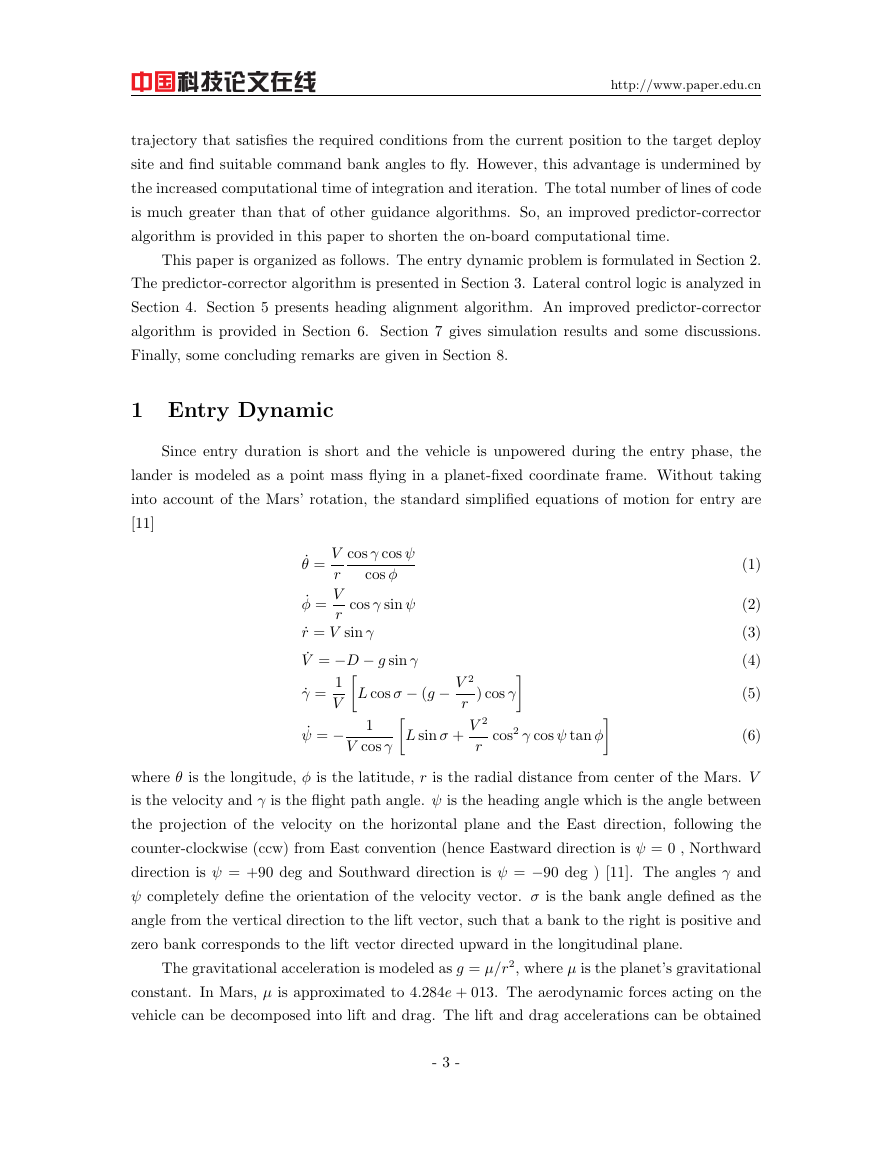
cycle of prediction in the future. C. W. Brunner and Ping Lu [10] proposed a more robust
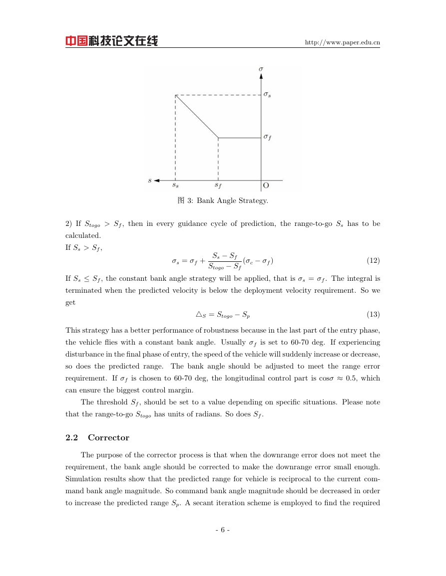
strategy, shown in Fig. 3. Ss and σs represent the range-to-go and bank angle in a certain
guidance cycle of prediction. Sf and σf are constants which need to be designed.
The algorithm for this strategy is as follows
1) If Stogo ≤ Sf , the constant bank angle strategy will be applied.
- 5 -
�
http://www.paper.edu.cn
图 3: Bank Angle Strategy.
2) If Stogo > Sf , then in every guidance cycle of prediction, the range-to-go Ss has to be
calculated.
If Ss > Sf ,
σs = σf +
Ss − Sf
Stogo − Sf
(σc − σf )
(12)
If Ss ≤ Sf , the constant bank angle strategy will be applied, that is σs = σf . The integral is
terminated when the predicted velocity is below the deployment velocity requirement. So we
get
△S = Stogo − Sp
(13)
This strategy has a better performance of robustness because in the last part of the entry phase,
the vehicle flies with a constant bank angle. Usually σf is set to 60-70 deg. If experiencing
disturbance in the final phase of entry, the speed of the vehicle will suddenly increase or decrease,
so does the predicted range. The bank angle should be adjusted to meet the range error
requirement. If σf is chosen to 60-70 deg, the longitudinal control part is cosσ ≈ 0.5, which
can ensure the biggest control margin.
The threshold Sf , should be set to a value depending on specific situations. Please note
that the range-to-go Stogo has units of radians. So does Sf .
2.2 Corrector
The purpose of the corrector process is that when the downrange error does not meet the
requirement, the bank angle should be corrected to make the downrange error small enough.
Simulation results show that the predicted range for vehicle is reciprocal to the current com-
mand bank angle magnitude. So command bank angle magnitude should be decreased in order
to increase the predicted range Sp. A secant iteration scheme is employed to find the required
- 6 -
�
http://www.paper.edu.cn
bank-angle magnitude. The iterates are generated by the equation [10]
cos σn+1 = cos σn − cos σn − cos σn1
△S(σn) − △S(σn1)
△S (σn)
(14)
It is clear from the above equation that two predicted downrange errors are needed to get the
new bank angle magnitude in this process.
To start the secant iteration scheme appropriately for the first time, an initial guess of
the bank angle is required. Considering that large bank angles can meet the constraints on
heat load, heat rate, and deceleration load, the algorithm begins by assuming an initial bank
angle of 80 deg in the numerical simulation of the trajectory. After the first guidance cycle,
the previously calculated bank angle is used as an initial guess rather than beginning with a
80 deg bank angle. If this angle is still sufficient to bring the downrange error within accepted
tolerance, the secant method is skipped and the previous bank angle is flown. Otherwise, the
secant method proceeds as already noted and determines a new bank-angle magnitude.
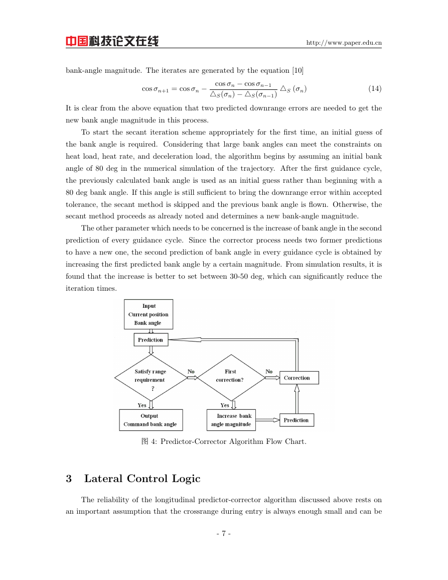
The other parameter which needs to be concerned is the increase of bank angle in the second
prediction of every guidance cycle. Since the corrector process needs two former predictions
to have a new one, the second prediction of bank angle in every guidance cycle is obtained by
increasing the first predicted bank angle by a certain magnitude. From simulation results, it is
found that the increase is better to set between 30-50 deg, which can significantly reduce the
iteration times.
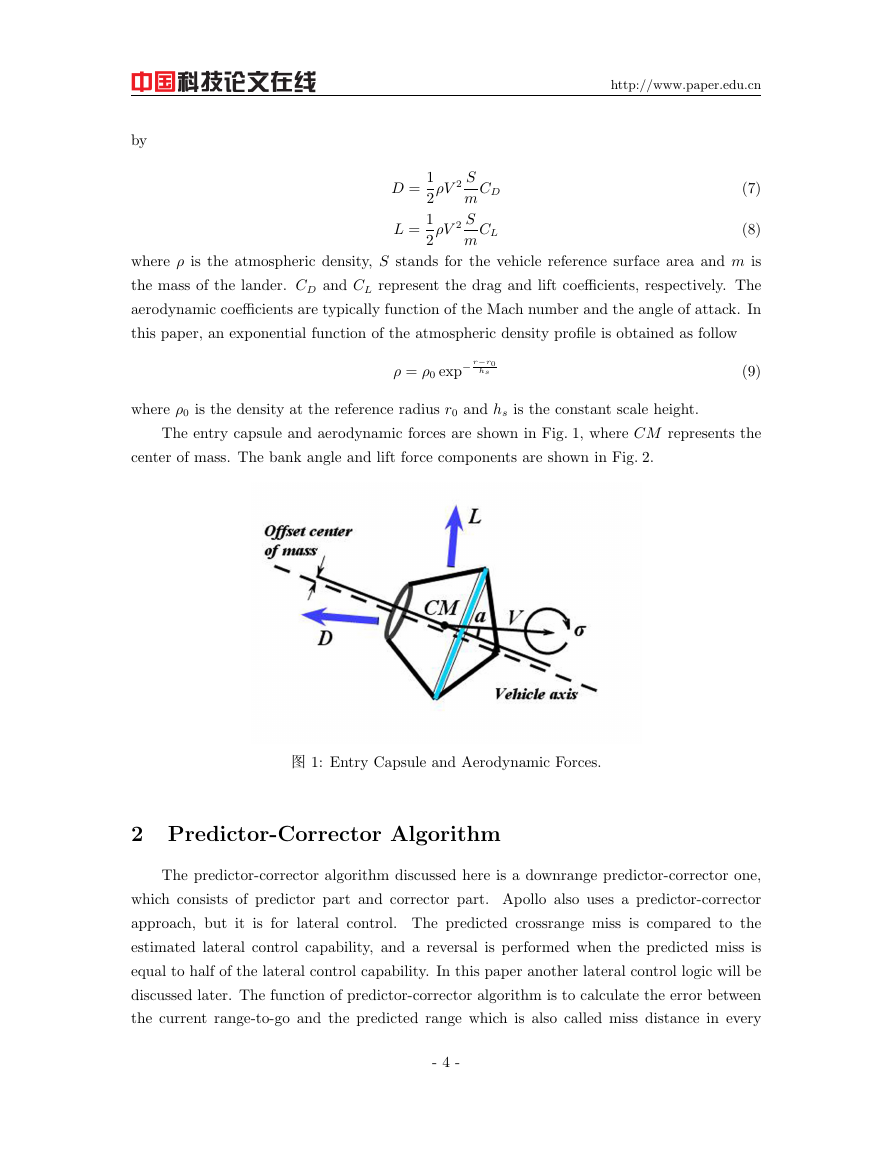
图 4: Predictor-Corrector Algorithm Flow Chart.
3 Lateral Control Logic
The reliability of the longitudinal predictor-corrector algorithm discussed above rests on
an important assumption that the crossrange during entry is always enough small and can be
- 7 -
�
http://www.paper.edu.cn
neglected. So the predicted range can be equal to the predicted downrange. And the range-to-
go is just the downrange-to-go defined as the great-circle distance between the current position
and the target deploy site. The ideal predictor-corrector algorithm is to make the predicted
downrange and the range-to-go equal. But as predicted downrange is hard to compute, pre-
dicted range is often used to substitute it in practice. So in order to actually fly toward the
target conditions, the lateral control logic should be used to confine the crossrange deviation to
an acceptable bound via bank angle reversals. There are mainly two methods of lateral control
for low lift-to-drag (L/D) ratios vehicles:
1) Bank reversal based on crossrange error.
2) Bank reversal based on azimuth angle error.
These two methods are alike in that when the error(crossrange error or azimuth angle
error) exceeds the pre-specify threshold, the sign of bank angle is reversed. A crossrange and
azimuth angle threshold is defined as a quadratic or simply a linear function of the dimensionless
velocity [10]
χc = c1V + c0
The crossrange can be calculated as
χ = arcsin [sin Stogo sin(ψ − Ψ)]
(15)
(16)
where Stogo is the range-to-go, ψ is the current heading angle, and Ψ is the line-of-sight azimuth
angle along a great circle to the landing site. All the variables have units of radians. Note that
the definition of heading angle discussed in this paper is different from that in some other
works(e.g. Ref.
[8]-[10]), the computation method of heading angle error will be given as
follows [11]
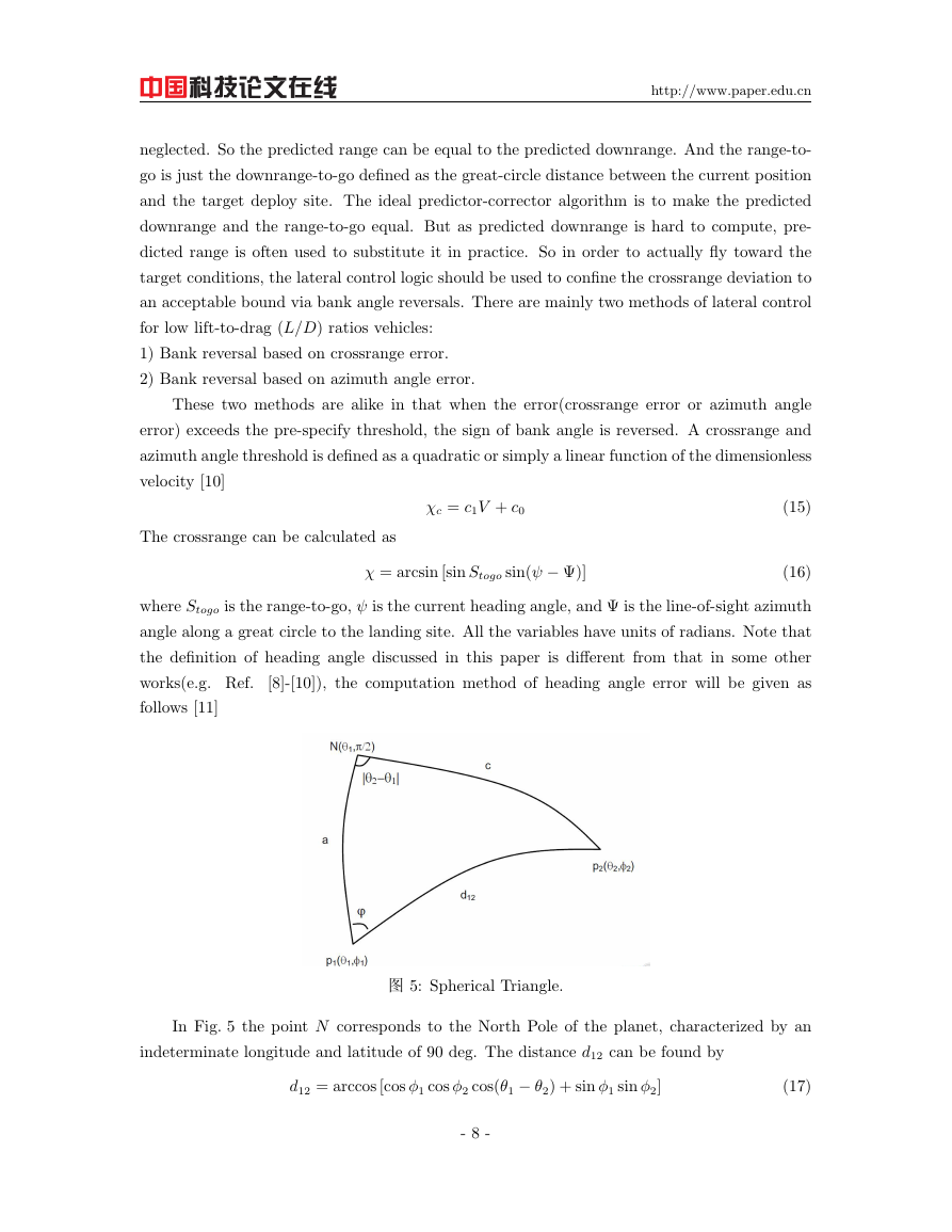
图 5: Spherical Triangle.
In Fig. 5 the point N corresponds to the North Pole of the planet, characterized by an
indeterminate longitude and latitude of 90 deg. The distance d12 can be found by
d12 = arccos [cos ϕ1 cos ϕ2 cos(θ1 − θ2) + sin ϕ1 sin ϕ2]
(17)
- 8 -
�


 2023年江西萍乡中考道德与法治真题及答案.doc
 2012年重庆南川中考生物真题及答案.doc
 2013年江西师范大学地理学综合及文艺理论基础考研真题.doc
 2020年四川甘孜小升初语文真题及答案I卷.doc
 2020年注册岩土工程师专业基础考试真题及答案.doc
 2023-2024学年福建省厦门市九年级上学期数学月考试题及答案.doc
 2021-2022学年辽宁省沈阳市大东区九年级上学期语文期末试题及答案.doc
 2022-2023学年北京东城区初三第一学期物理期末试卷及答案.doc
 2018上半年江西教师资格初中地理学科知识与教学能力真题及答案.doc
 2012年河北国家公务员申论考试真题及答案-省级.doc
 2020-2021学年江苏省扬州市江都区邵樊片九年级上学期数学第一次质量检测试题及答案.doc
 2022下半年黑龙江教师资格证中学综合素质真题及答案.doc