CAPL Callback Interface in CANoe
Version 1.3
2017-04-11
Application Note AN-IND-1-012
Author
Vector Informatik GmbH
Restrictions Public Document
Abstract
Information and explanation on the CAPL Callback Interface (CCI) for diagnostics in
CANoe, including examples and references
Table of Contents
1.0 Overview ........................................................................................................................................ 2
2.0 Background ................................................................................................................................... 2
2.1 What is the CCI? .................................................................................................................. 2
2.2 Why use the CCI? ................................................................................................................ 2
2.3
Alternatives to using the CCI ............................................................................................... 2
2.4 What can you do with the CCI? ........................................................................................... 3
3.0 Basic concept of the CAPL callback interface for diagnostics ................................................ 3
CAPL functions called by the CCI ........................................................................................ 3
3.1
CCI functions called by CAPL .............................................................................................. 3
3.2
Additional configuration steps necessary ............................................................................ 4
3.3
Configuration parameters provided by CANoe .................................................................... 4
3.4
3.5 Walkthrough: Basic CCI for ISO TP on CAN ....................................................................... 5
3.5.1 Tester side ........................................................................................................................... 5
3.5.2 ECU simulation side ............................................................................................................. 6
4.0 Concrete implementations for several bus types and protocols ............................................. 6
Example how to use the CCI include files in an ECU simulation ......................................... 6
Example how to use the CCI include files in a Test Module ................................................ 9
Additional hints when using the LIN CCI ...........................................................................10
Additional hints when using VW TP 2.0 on CAN ...............................................................10
5.0 Additional functionality (independent of bus type) .................................................................11
Session management ........................................................................................................11
Simulate special ECU response timing behavior ...............................................................11
6.0 Advanced feature: Fault injection .............................................................................................12
Background ........................................................................................................................12
6.1
Fault injection without the need to use the CCI .................................................................12
6.2
Example using OSEK_TP.DLL ..........................................................................................13
6.3
6.3.1 Basic concept and more information..................................................................................13
6.3.2 Dropping a TP frame ..........................................................................................................13
7.0 Additional Resources .................................................................................................................14
8.0 Contacts .......................................................................................................................................14
4.1
4.2
4.3
4.4
5.1
5.2
�
CAPL Callback Interface in CANoe
1.0 Overview
This document explains the background and usage of the “CAPL callback interface for diagnostics”
(CCI, first introduced in CANoe 5.1), for CANoe 8.5 and later versions. It will assist a developer in
deciding whether using the CCI is the right choice, and help implement it in that case.
2.0 Background
This section gives high-level answers the following questions:
> What is the CCI?
> Why use it?
> What are the alternatives?
> What can you do with it?
2.1 What is the CCI?
The CCI is a completely generic way to connect the diagnostics layer of a CAPL program with the
transport layer: A separate set of CAPL functions is used to forward diagnostics data to the network,
receive data from the network and process it as diagnostics data.
Once a diagnostics description database is configured to be used either by a tester node or a
simulation node, the CCI for diagnostics becomes available in the respective CAPL programs.
Diagnostics descriptions can be either Basic Diagnostic Descriptions, CANdela “.cdd” files, ODX
databases - typically provided as “.pdx” archives – or “.mdx”-Files.
The CCI has a very small interface, which requires the implementation of only a few CAPL functions
for ECU simulations and diagnostics testers.
2.2 Why use the CCI?
CANoe provides standard channels for diagnostic communication with ECUs as a diagnostics tester
(since CANoe 5.2) and ECU simulation (since CANoe 10.0). These built-in channels are supported on
> CAN (ISO TP/VW TP2.0)
> LIN
> K-Line
> FlexRay (several TP standards) and
> DoIP/HSFZ.
They handle the transfer and reception of diagnostic requests and responses on the network. In the
CAPL code the developer can completely focus on the application itself e.g. define a request, modify
its symbolical parameters as defined in the diagnostic database and send the request.
In some use cases though using the CCI is recommended:
> Advanced simulation of a diagnostics ECU in a CAPL program (use case “test the tester”).
> Using a transport protocol (version) that is not yet supported directly in CANoe.
> Changing protocol parameters and behavior in a way not supported by standard CANoe means.
> Perform violations of the diagnostics protocol in order to implement special tests of the diagnostics
functionality of an ECU.
2.3 Alternatives to using the CCI
For most use cases, it is not necessary to implement the CCI in a diagnostics tester or ECU
simulation.
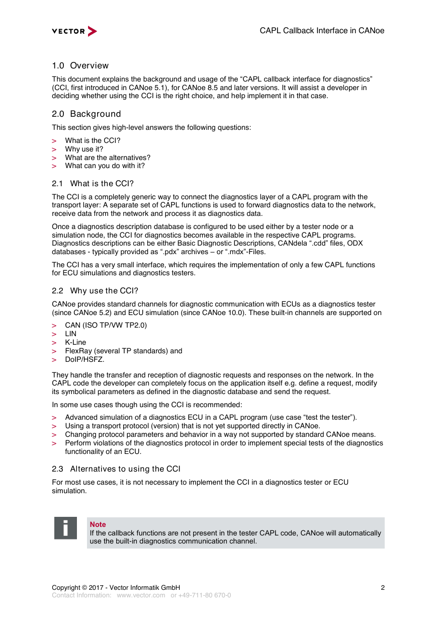
Note
If the callback functions are not present in the tester CAPL code, CANoe will automatically
use the built-in diagnostics communication channel.
Copyright © 2017 - Vector Informatik GmbH
Contact Information: www.vector.com or +49-711-80 670-0
2
�
CAPL Callback Interface in CANoe
In some cases it is possible to use a gateway or proxy on a supported bus technology (e.g. CAN) with
a supported transport protocol (e.g. ISO TP). All CANoe features are available in this case, only the
gateway or proxy has to forward the data to and from the ECU.
You may want to read the application note AN-IND-1-004 “Diagnostics via Gateway in CANoe”, which
lists different concepts of implementing such gateway nodes. This use case of CANoe is also of
special interest for users who need a diagnostic gateway e.g. in early development stages where the
gateway hardware to access the ECU is not readily available to developers or testers.
Finally in rare cases it may be more efficient to implement the communication on transport protocol
level directly, especially if no (standard) diagnostics description can be used.
2.4 What can you do with the CCI?
The following is a list of tasks possible once the CCI is implemented:
> Change CAN identifiers to test if the ECU only responds to the IDs it was assigned to.
> Delay response messages from an ECU simulation for an arbitrary amount of time to test the
timeout implementation in a tester.
> Delay transport protocol messages individually to check the transport protocol implementation in
the ECU for correct handling of timeouts.
> Change the content of individual transport protocol messages, like padding byte values.
> Make the tester or ECU simulation send transport protocol messages which do not conform to the
specification and should cause some error reaction in the receiver.
> Any use-case specific non-standard handling that needs direct access to the transport protocol
layer, and non-standard changes to the diagnostics protocol.
3.0 Basic concept of the CAPL callback interface for diagnostics
The CCI works as glue between the diagnostics and transport protocol layers: Whenever a diagnostics
object (diagRequest or diagResponse) is sent by the CAPL program, its data is forwarded to the
transport protocol, which transfers it on the bus. In addition there are CAPL functions that control the
setup and status of the communication connections, and functions that provide information to the CCI.
3.1 CAPL functions called by the CCI
The following CAPL functions are called by the CCI when specific events occur. The functions are
denoted by a underscore “_” at the start of the function name. The CAPL program has to perform
actions that depend on the concrete transport protocol or use case.
> void _Diag_SetChannelParameters()
The CAPL program is instructed to configure a communications channel to the peer (in a tester
node to the ECU, and vice versa). The transport protocol parameters are typically retrieved from
CANoe or hard-coded values might be used as well.
In a tester, this function is called every time DiagSetTarget is called, in an ECU simulation it is
called during measurement start.
> void _Diag_DataRequest (BYTE data[], DWORD count, long furtherSegments);
The provided data has to be sent to the peer. If the argument furtherSegments is non-zero, the
data is segmented and may be sent in a special way. Please refer to section 4.4 for details.
> void _Diag_SetupChannelReq();
Called only in a tester before the first request is sent to indicate that a communications channel to
the ECU should be established. Connection-oriented protocols need to perform a “channel setup”
step, while for most connection-less protocols (like ISO/OSEK TP), nothing has to be done. In
latter case it suffices to call Diag_SetupChannelCon() immediately.
> void _Diag_SendFunctional();
Called only in a tester, when a functional request is sent (by the CAPL function
DiagSendFunctional).
3.2 CCI functions called by CAPL
The following functions are implemented by CANoe and can be called from the CAPL code. Note the
prefix Diag_ differentiating the functions from other diagnostics related CAPL functions.
Copyright © 2017 - Vector Informatik GmbH
Contact Information: www.vector.com or +49-711-80 670-0
3
�
CAPL Callback Interface in CANoe
> long Diag_ClosedChannelInd ();
This function communicates to CANoe that the communication channel is no longer available, e.g.
the tester closed the channel or a non-reparable error occurred. The CAPL program has to call
Diag_SetupChannelCon before further data can be sent.
> void Diag_DataCon (long count);
Tells the diagnostic layer that the given number of bytes of data were transmitted successfully.
> void Diag_DataInd (byte rxBuffer[], long count, long sender);
The given amount of data was received from the peer.
> void Diag_ErrorInd( long error);
Forwards errors to the diagnostics layer, e.g. to stop a function waiting for a diagnostics response.
> void Diag_FirstFrameInd( long source, long dest, long totalLength);
The peer has started to send data of given total length. In a tester node the timer waiting for a
reaction from the ECU can be stopped. In an ECU simulation the session timer can be stopped.
> long Diag_SetDataSegmentation( long mode, DWORD maxSegmentSize,
DWORD segmentSeparationTime);
Configure the handling of diagnostics data segmentation. Almost no protocol uses segmentation;
therefore it is deactivated per default. Please refer to section 4.4 for details.
> long Diag_SetupChannelCon();
The tester has established a connection to the ECU successfully, or it is not necessary to open a
connection at all. This function is not needed in an ECU simulation.
3.3 Additional configuration steps necessary
The following configuration steps have to be performed to allow the CCI to take configuration
parameters from the settings of a specific diagnostics description.
>
“Configuration | Diagnostics/ISO TP…”: Configure the diagnostics description that should be used
in the tester or simulation node. The setting for “Usage of the diagnostics description” must not be
“Interpretation only”. For all other settings, the CCI is available; for an ECU simulation the
simulation node has to be assigned here. Alternatively, an ECU simulation node can call the CAPL
function DiagInitEcuSimulation in its 'on prestart' handler.
> Simulation node “Configuration…” dialog: On page “Modules”, the respective transport protocol
nodelayer DLL has to be configured. It is also possible to specify this DLL in a DBC file of a
network via the attribute NodeLayerModules e.g. entering osek_tp.dll there.
3.4 Configuration parameters provided by CANoe
With the CCI functions documented so far, diagnostics communication can be configured by using
hard-coded values (i.e. specifying the arguments directly in the CAPL code), or retrieving parameters
from other source, e.g. a DBC file. Yet in order to write a CCI implementation that can adapt itself to
the communication parameters stored inside the diagnostics descriptions configured in CANoe, the
mechanism described below has to be used.
Using a set of string handles, CANoe will provide numeric values depending on the active diagnostics
description:
long DiagGetCommParameter (char qualifier[]);
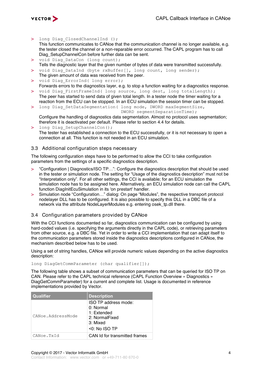
The following table shows a subset of communication parameters that can be queried for ISO TP on
CAN. Please refer to the CAPL technical reference (CAPL Function Overview » Diagnostics »
DiagGetCommParameter) for a current and complete list. Usage is documented in reference
implementations provided by Vector.
Qualifier
Description
CANoe.AddressMode
ISO TP address mode:
0: Normal
1: Extended
2: NormalFixed
3: Mixed
<0: No ISO TP
CANoe.TxId
CAN Id for transmitted frames
Copyright © 2017 - Vector Informatik GmbH
Contact Information: www.vector.com or +49-711-80 670-0
4
�
CAPL Callback Interface in CANoe
Qualifier
CANoe.RxId
Description
CAN Id for received frames
CANoe.BaseAddress
TP base address
CANoe.EcuAddr
CANoe.TgtAddr
Number of this node
Target node number
CANoe.AddrExt
Address extension byte
CANoe.TxPrio
Frame transmit priority
Table 1 - Communication parameters for ISO TP connections on CAN
3.5 Walkthrough: Basic CCI for ISO TP on CAN
In this section the workflow of a basic CCI for ISO TP on CAN is explained in detail.
3.5.1 Tester side
CAPL code
CCI Callback function
CAPL for OSEK_TP.DLL
DiagSetTarget( ecu)
The tester code selects the
diagnostics target to
communicate with
_Diag_SetChannelParamete
rs(…)
The CCI function is called to
allow configuration of the
communication layer
CanTpCreateConnection(…)
Create a TP connection and
configure it
CAPL code
CCI Callback function
CAPL for OSEK_TP.DLL
DiagSendRequest( object)
A request should be sent to the
ECU
_Diag_SetupChannelReq()
For the first sending of data
only, the CCI is instructed to
open a communication channel
Diag_SetupChannelCon()
Since ISO TP is a connection-
less protocol, the confirmation
can be given immediately
_Diag_DataRequest(…)
The CCI is instructed to send
data
CanTpSendData()
Send data on the connection
CAPL code
CCI Callback function
CAPL for OSEK_TP.DLL
DiagSendFunctional(reque
st)
A functional request should be
sent
_Diag_SendFunctional(…)
The CCI is instructed to send a
functional request
CanTpSendData()
Send data on all TP connections
which belong to the addressed
functional group
Callback called by DLL
Diagnostic CAPL function Event in CAPL
CanTp_SendCon()
The TP confirms the sending of
the request data
Diag_DataCon()
The diagnostics layer is
informed that the request has
been sent
e.g
TestWaitForDiagRequestSe
nt() would continue
Callback called by DLL
Diagnostic CAPL function Event in CAPL
CanTp_FirstFrameInd()
Start of data reception
Diag_FirstFrameInd()
Indicate the start of data
reception
e.g.
TestWaitForDiagResponseS
tart() would continue;
Diagnostics timers are stopped
Callback called by DLL
Diagnostic CAPL function Event in CAPL
CanTp_ReceptionInd()
Reception of Data
Diag_DataInd(…)
The response data is forwarded
for diagnostics processing
TestWaitForDiagResponse(
)
test functions waiting for a
response continue
On diagResponse ... {…}
response handlers are called
Copyright © 2017 - Vector Informatik GmbH
Contact Information: www.vector.com or +49-711-80 670-0
5
�
CAPL Callback Interface in CANoe
3.5.2 ECU simulation side
Event
CCI Callback function
Typical implementation
Measurement start
A diagnostics description is
assigned to the simulation node
_Diag_SetChannelParamete
rs(…)
The CCI function is called to
allow configuration of the
communication layer
CanTpCreateConnection(…)
;
Create a TP connection and
configure it
Callback called by DLL
Diagnostic CAPL function Event in CAPL
CanTp_ReceptionInd()
A request has been received
Diag_DataInd(…)
The request data is forwarded
for diagnostics processing
On diagRequest …{…}
The corresponding handler
function is called
CAPL code
CCI Callback function
CAPL for OSEK_TP.DLL
DiagSendResponse()
Send a response object for the
request
_Diag_DataRequest(…)
Forward the data of the
response to the TP
CanTpSendData(…)
Send data on the connection
4.0 Concrete implementations for several bus types and protocols
Starting with CANoe 8.5, CCI reference implementations are included in the directory
“%PUBLIC%\Documents\Vector\CANoe\\Reusable\CAPL_Includes\Diagnostics” (replace
in the path by your CANoe version). These CCI implementations may be used both in tester
and ECU simulation nodes; please look for special instructions in the global variable sections. They do
not support session handling.
CANoe provides a CCI reference implementation for the following transport protocols:
Transport protocol
CCI include file
Corresponding TP DLL1
ISO15765-2 TP on CAN
(formerly known as “OSEK TP”)2
CCI_CanTP.cin
LIN TP
ISO 10681-2 FlexRay TP
AUTOSAR FlexRay TP
DoIP/HSFZ
CCI_LINTP.cin
CCI_FrAsrTP.cin3
CCI_FrISOTP.cin3
CCI_DoIP.cin
osek_tp.dll
LINtp.dll
FlexRayTPISO.DLL
AutosarFlexRayTP3.dll
DoIP.dll
K-Line (ECU simulation only)
CCI_KLine.cin
- (none necessary)
4.1 Example how to use the CCI include files in an ECU simulation
The following example shows how to use the CCI reference implementation corresponding to the
ISO15765-2 TP on CAN implementation in “osek_tp.dll”:
1. Open the simulation setup and add a new Network Node.
2. From the context menu of the new node, choose “Configuration…” and select the tab “Common”.
1 These transport protocol DLLs are located in the EXEC32-folder of your CANoe installation.
2 Please refer to the “OSEK TP DLL” page in the CANoe online help for additional details.
3 The FlexRay CCI include files both reference the include file „CCI_FrCommon.cin“ which contains
the common subset for both FlexRay TP implementations.
Copyright © 2017 - Vector Informatik GmbH
Contact Information: www.vector.com or +49-711-80 670-0
6
�
CAPL Callback Interface in CANoe
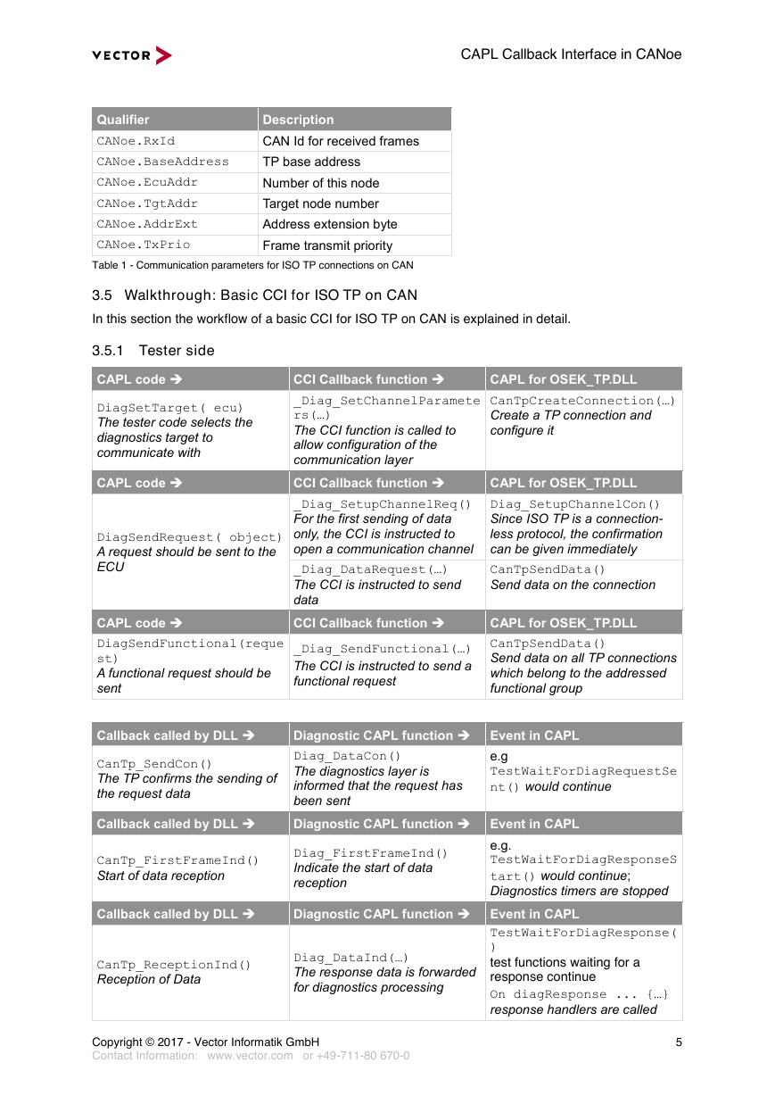
3. Optionally assign a network node from your network description database (you may create such a
database e.g. with the CANdb++ Editor):
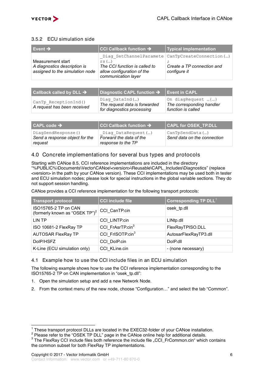
4. Select the tab “Components” and confirm that the necessary TP DLL is already configured for this
node based on the added database. If the database does not reference the TP DLL or you did not
assign a network node from a database, you may add the DLL manually, choosing the respective
DLL (here: “osek_tp.dll”) provided in the EXEC32-folder of your CANoe installation. In this case,
the DLL is added to all assigned buses:
Copyright © 2017 - Vector Informatik GmbH
Contact Information: www.vector.com or +49-711-80 670-0
7
�
CAPL Callback Interface in CANoe
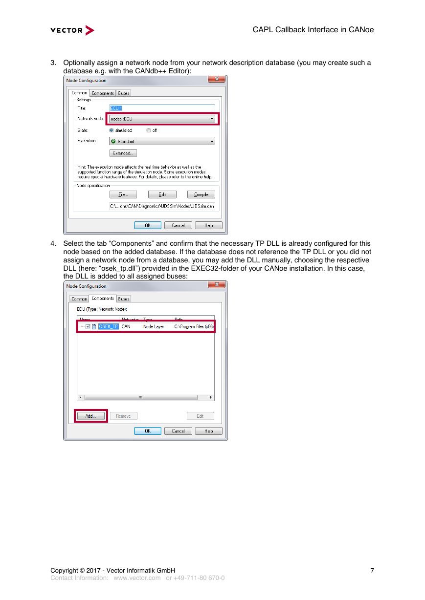
5. Open the “Configuration | Diagnostics/ISO TP…” dialog, add a diagnostics description for your
ECU, and specify a unique ECU qualifier for it. Select the node from the simulation setup at
“Simulation by”:
6. Add the following CAPL code to your network node:
includes
{
// Include the CAPL Callback Interface (CCI) reference implementation for CAN TP
#include "Diagnostics\CCI_CanTP.cin"
}
variables
{
// Define constants necessary for the CCI reference implementation
char gECU[20]="CAN_ECU"; // ECU qualifier defined in the
// "Configuration | Diagnostics/ISO TP..." dialog
int cIsTester=0; // This is a simulation node, no tester node
}
on preStart
{
// Provide the link to the configured diagnostics description
diagInitEcuSimulation(gECU);
}
// Very simple implementation of diagnostics services supported by this simulation
// Only "Tester Present" is answered by a positive response, all other services by
negative response
on diagRequest *
{
diagResponse this resp;
diagSendNegativeResponse(resp, 0x11); // Service not supported
}
on diagRequest TesterPresent_Process
{
diagResponse this resp;
diagSendPositiveResponse(resp);
}
7. You may add additional “on diagRequest ” handlers for all diagnostic services you want
to support with your simulation and change the value of “gECU” to the ECU qualifier you defined in
the “Configuration | Diagnostics/ISO TP…” dialog. Additionally, you might need to adapt the
Copyright © 2017 - Vector Informatik GmbH
Contact Information: www.vector.com or +49-711-80 670-0
8
�


 2023年江西萍乡中考道德与法治真题及答案.doc
 2012年重庆南川中考生物真题及答案.doc
 2013年江西师范大学地理学综合及文艺理论基础考研真题.doc
 2020年四川甘孜小升初语文真题及答案I卷.doc
 2020年注册岩土工程师专业基础考试真题及答案.doc
 2023-2024学年福建省厦门市九年级上学期数学月考试题及答案.doc
 2021-2022学年辽宁省沈阳市大东区九年级上学期语文期末试题及答案.doc
 2022-2023学年北京东城区初三第一学期物理期末试卷及答案.doc
 2018上半年江西教师资格初中地理学科知识与教学能力真题及答案.doc
 2012年河北国家公务员申论考试真题及答案-省级.doc
 2020-2021学年江苏省扬州市江都区邵樊片九年级上学期数学第一次质量检测试题及答案.doc
 2022下半年黑龙江教师资格证中学综合素质真题及答案.doc