NXDN
®
NXDN Technical Specifications
Part 2:
Conformance Test
Sub-part B:
Common Air Interface Test
NXDN TS 2-B Version 1.2
November 2012
NXDN Forum
�
Part 2-B Common Air Interface Test Ver.1.2
4.1.
4.2.1.
4.2.2.
4.2.3.
4.2.4.
4.1.1.
4.1.2.
4.1.3.
4.1.4.
4.1.5.
4.1.6.
4.1.7.
4.1.8.
4.1.9.
4.1.10.
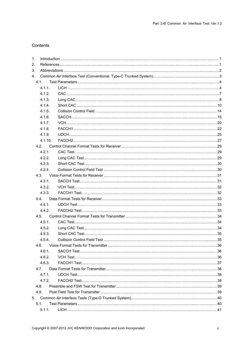
Contents
1.
Introduction .......................................................................................................................................................1
2. References........................................................................................................................................................1
3. Abbreviations ....................................................................................................................................................2
4. Common Air Interface Test (Conventional, Type-C Trunked System)...............................................................3
Test Parameters .......................................................................................................................................4
LICH .................................................................................................................................................4
CAC..................................................................................................................................................7
Long CAC.........................................................................................................................................8
Short CAC ......................................................................................................................................10
Collision Control Field ....................................................................................................................14
SACCH...........................................................................................................................................15
VCH................................................................................................................................................20
FACCH1.........................................................................................................................................22
UDCH.............................................................................................................................................25
FACCH2.........................................................................................................................................27
Control Channel Format Tests for Receiver ...........................................................................................29
CAC Test........................................................................................................................................29
Long CAC Test...............................................................................................................................29
Short CAC Test ..............................................................................................................................30
Collision Control Field Test ............................................................................................................30
Voice Format Tests for Receiver ............................................................................................................31
SACCH Test...................................................................................................................................31
VCH Test........................................................................................................................................32
FACCH1 Test.................................................................................................................................32
Data Format Tests for Receiver..............................................................................................................33
UDCH Test.....................................................................................................................................33
FACCH2 Test.................................................................................................................................33
Control Channel Format Tests for Transmitter .......................................................................................34
CAC Test........................................................................................................................................34
Long CAC Test...............................................................................................................................34
Short CAC Test ..............................................................................................................................35
Collision Control Field Test ............................................................................................................35
Voice Format Tests for Transmitter ........................................................................................................36
SACCH Test...................................................................................................................................36
VCH Test........................................................................................................................................36
FACCH1 Test.................................................................................................................................37
Data Format Tests for Transmitter..........................................................................................................38
UDCH Test.....................................................................................................................................38
FACCH2 Test.................................................................................................................................38
Preamble and FSW Test for Transmitter ................................................................................................39
Post Field Test for Transmitter ...............................................................................................................39
5. Common Air Interface Tests (Type-D Trunked System)..................................................................................40
Test Parameters .....................................................................................................................................40
LICH ...............................................................................................................................................41
4.5.1.
4.5.2.
4.5.3.
4.5.4.
4.6.1.
4.6.2.
4.6.3.
4.7.1.
4.7.2.
4.3.1.
4.3.2.
4.3.3.
4.4.1.
4.4.2.
4.7.
4.8.
4.9.
5.1.
5.1.1.
4.2.
4.3.
4.4.
4.5.
4.6.
Copyright © 2007-2012 JVC KENWOOD Corporation and Icom Incorporated
ii
�
Part 2-B Common Air Interface Test Ver.1.2
5.3.
5.4.
5.3.1.
5.3.2.
5.4.1.
5.4.2.
5.4.3.
5.5.1.
5.5.2.
5.2.1.
5.2.2.
5.2.3.
5.1.2.
5.1.3.
5.1.4.
5.1.5.
5.1.6.
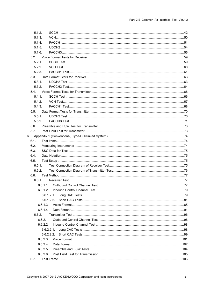
SCCH .............................................................................................................................................42
VCH................................................................................................................................................50
FACCH1.........................................................................................................................................51
UDCH2...........................................................................................................................................54
FACCH3.........................................................................................................................................56
Voice Format Tests for Receiver ............................................................................................................59
SCCH Test .....................................................................................................................................59
VCH Test........................................................................................................................................60
FACCH1 Test.................................................................................................................................61
Data Format Tests for Receiver..............................................................................................................63
UDCH2 Test...................................................................................................................................63
FACCH3 Test.................................................................................................................................64
Voice Format Tests for Transmitter ........................................................................................................66
SCCH Test .....................................................................................................................................66
VCH Test........................................................................................................................................67
FACCH1 Test.................................................................................................................................68
Data Format Tests for Transmitter..........................................................................................................70
UDCH2 Test...................................................................................................................................70
FACCH3 Test.................................................................................................................................71
Preamble and FSW Test for Transmitter ................................................................................................73
Post Field Test for Transmitter ...............................................................................................................73
6. Appendix 1 (Conventional, Type-C Trunked System) .....................................................................................74
6.1.
Test Items...............................................................................................................................................74
6.2. Measuring Instruments ...........................................................................................................................74
6.3.
SSG Data for Test ..................................................................................................................................75
Data Notation..........................................................................................................................................75
6.4.
Test Setup ..............................................................................................................................................75
6.5.
Test Connection Diagram of Receiver Test....................................................................................75
Test Connection Diagram of Transmitter Test................................................................................76
Test Method............................................................................................................................................77
Receiver Test .................................................................................................................................77
6.6.1.1. Outbound Control Channel Test.................................................................................................77
Inbound Control Channel Test ...................................................................................................79
6.6.1.2.
6.6.1.2.1. Long CAC Tests ..................................................................................................................79
6.6.1.2.2. Short CAC Tests..................................................................................................................81
6.6.1.3. Voice Format..............................................................................................................................85
6.6.1.4. Data Format ...............................................................................................................................91
Transmitter Test .............................................................................................................................96
6.6.2.1. Outbound Control Channel Test.................................................................................................96
Inbound Control Channel Test ...................................................................................................98
6.6.2.2.
6.6.2.2.1. Long CAC Tests ..................................................................................................................98
6.6.2.2.2. Short CAC Tests..................................................................................................................99
6.6.2.3. Voice Format............................................................................................................................101
6.6.2.4. Data Format .............................................................................................................................102
6.6.2.5. Preamble and FSW Tests ........................................................................................................104
6.6.2.6. Post Field Test for Transmission..............................................................................................105
Test Frame ...........................................................................................................................................106
6.5.1.
6.5.2.
6.6.1.
6.6.
6.6.2.
5.2.
5.5.
5.6.
5.7.
6.7.
Copyright © 2007-2012 JVC KENWOOD Corporation and Icom Incorporated
iii
�
Part 2-B Common Air Interface Test Ver.1.2
6.8.
6.9.
7.6.1.
7.6.2.
6.7.1.
6.7.2.
6.7.3.
6.7.4.
6.7.5.
6.7.6.
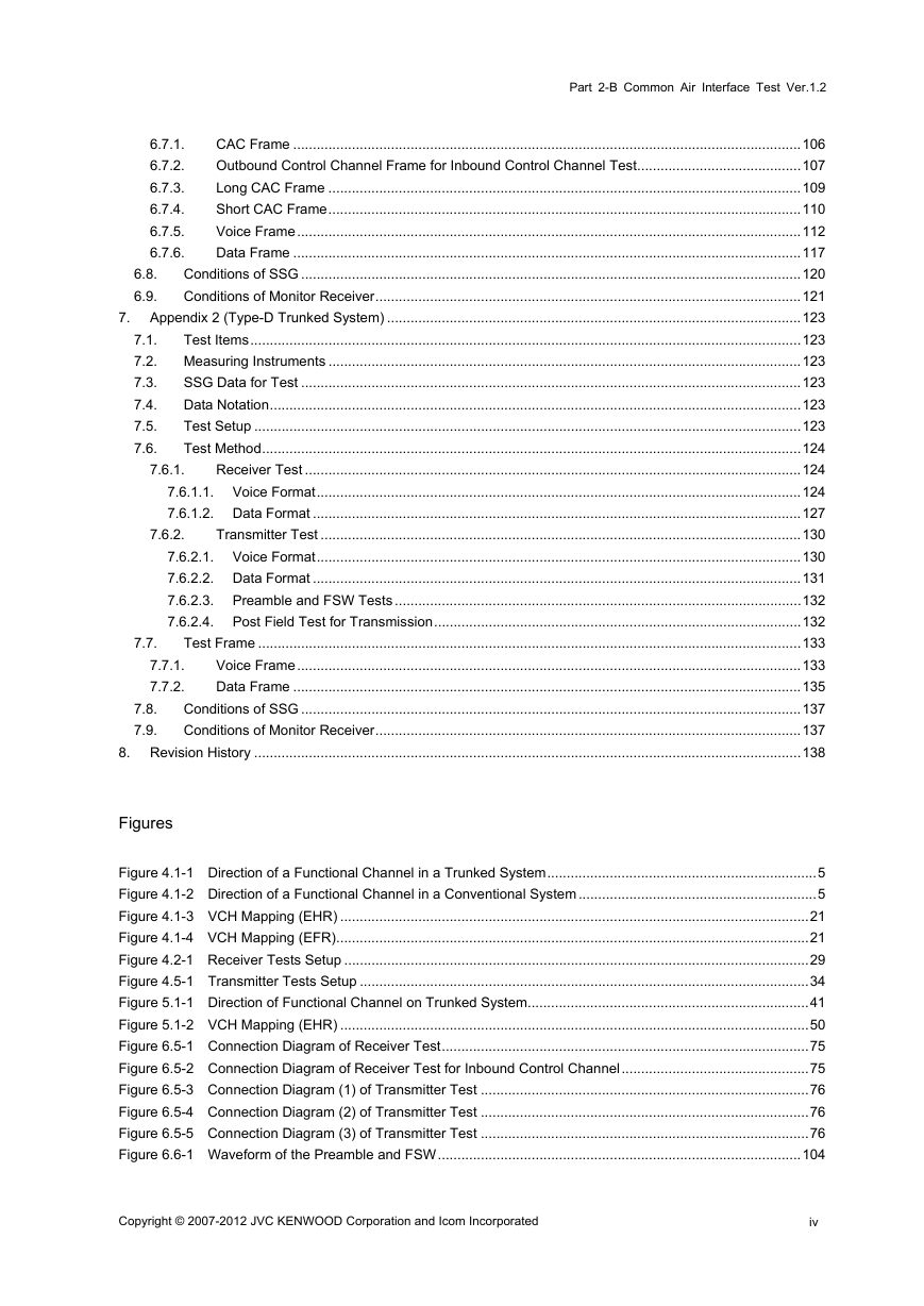
CAC Frame ..................................................................................................................................106
Outbound Control Channel Frame for Inbound Control Channel Test..........................................107
Long CAC Frame .........................................................................................................................109
Short CAC Frame.........................................................................................................................110
Voice Frame.................................................................................................................................112
Data Frame ..................................................................................................................................117
Conditions of SSG ................................................................................................................................120
Conditions of Monitor Receiver.............................................................................................................121
7. Appendix 2 (Type-D Trunked System) ..........................................................................................................123
7.1.
Test Items.............................................................................................................................................123
7.2. Measuring Instruments .........................................................................................................................123
SSG Data for Test ................................................................................................................................123
7.3.
Data Notation........................................................................................................................................123
7.4.
7.5.
Test Setup ............................................................................................................................................123
Test Method..........................................................................................................................................124
7.6.
Receiver Test ...............................................................................................................................124
7.6.1.1. Voice Format............................................................................................................................124
7.6.1.2. Data Format .............................................................................................................................127
Transmitter Test ...........................................................................................................................130
7.6.2.1. Voice Format............................................................................................................................130
7.6.2.2. Data Format .............................................................................................................................131
7.6.2.3. Preamble and FSW Tests ........................................................................................................132
7.6.2.4. Post Field Test for Transmission..............................................................................................132
Test Frame ...........................................................................................................................................133
Voice Frame.................................................................................................................................133
Data Frame ..................................................................................................................................135
Conditions of SSG ................................................................................................................................137
Conditions of Monitor Receiver.............................................................................................................137
8. Revision History ............................................................................................................................................138
Figures
Figure 4.1-1 Direction of a Functional Channel in a Trunked System.....................................................................5
Figure 4.1-2 Direction of a Functional Channel in a Conventional System .............................................................5
Figure 4.1-3 VCH Mapping (EHR) ........................................................................................................................21
Figure 4.1-4 VCH Mapping (EFR).........................................................................................................................21
Figure 4.2-1 Receiver Tests Setup .......................................................................................................................29
Figure 4.5-1 Transmitter Tests Setup ...................................................................................................................34
Figure 5.1-1 Direction of Functional Channel on Trunked System........................................................................41
Figure 5.1-2 VCH Mapping (EHR) ........................................................................................................................50
Figure 6.5-1 Connection Diagram of Receiver Test..............................................................................................75
Figure 6.5-2 Connection Diagram of Receiver Test for Inbound Control Channel................................................75
Figure 6.5-3 Connection Diagram (1) of Transmitter Test ....................................................................................76
Figure 6.5-4 Connection Diagram (2) of Transmitter Test ....................................................................................76
Figure 6.5-5 Connection Diagram (3) of Transmitter Test ....................................................................................76
Figure 6.6-1 Waveform of the Preamble and FSW.............................................................................................104
7.7.1.
7.7.2.
7.7.
7.8.
7.9.
Copyright © 2007-2012 JVC KENWOOD Corporation and Icom Incorporated
iv
�
Part 2-B Common Air Interface Test Ver.1.2
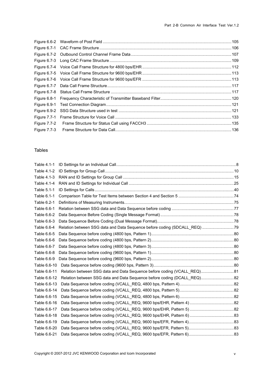
Figure 6.6-2 Waveform of Post Field ..................................................................................................................105
Figure 6.7-1 CAC Frame Structure.....................................................................................................................106
Figure 6.7-2 Outbound Control Channel Frame Data .........................................................................................107
Figure 6.7-3 Long CAC Frame Structure ............................................................................................................109
Figure 6.7-4 Voice Call Frame Structure for 4800 bps/EHR ...............................................................................112
Figure 6.7-5 Voice Call Frame Structure for 9600 bps/EHR ...............................................................................113
Figure 6.7-6 Voice Call Frame Structure for 9600 bps/EFR ...............................................................................113
Figure 6.7-7 Data Call Frame Structure..............................................................................................................117
Figure 6.7-8 Status Call Frame Structure ...........................................................................................................117
Figure 6.8-1 Frequency Characteristic of Transmitter Baseband Filter...............................................................120
Figure 6.9-1 Test Connection Diagram...............................................................................................................121
Figure 6.9-2 SSG Data Structure used in test ....................................................................................................121
Figure 7.7-1 Frame Structure for Voice Call .......................................................................................................133
Figure 7.7-2
Frame Structure for Status Call using FACCH3 ...........................................................................135
Figure 7.7-3
Frame Structure for Data Call.......................................................................................................136
Tables
Table 4.1-1 ID Settings for an Individual Call..........................................................................................................8
Table 4.1-2 ID Settings for Group Call..................................................................................................................10
Table 4.1-3 RAN and ID Settings for Group Call ..................................................................................................15
Table 4.1-4 RAN and ID Settings for Individual Call .............................................................................................25
Table 5.1-1 ID Settings for Calls...........................................................................................................................40
Table 6.1-1 Comparison Table for Test Items between Section 4 and Section 5 .................................................74
Table 6.2-1 Definitions of Measuring Instruments.................................................................................................75
Table 6.6-1 Relation between SSG data and Data Sequence before coding .......................................................77
Table 6.6-2 Data Sequence Before Coding (Single Message Format) .................................................................78
Table 6.6-3 Data Sequence Before Coding (Dual Message Format)....................................................................78
Table 6.6-4 Relation between SSG data and Data Sequence before coding (SDCALL_REQ) ............................79
Table 6.6-5 Data Sequence before coding (4800 bps, Pattern 1).........................................................................80
Table 6.6-6 Data Sequence before coding (4800 bps, Pattern 2).........................................................................80
Table 6.6-7 Data Sequence before coding (4800 bps, Pattern 3).........................................................................80
Table 6.6-8 Data Sequence before coding (9600 bps, Pattern 1).........................................................................80
Table 6.6-9 Data Sequence before coding (9600 bps, Pattern 2).........................................................................80
Table 6.6-10 Data Sequence before coding (9600 bps, Pattern 3).......................................................................80
Table 6.6-11 Relation between SSG data and Data Sequence before coding (VCALL_REQ).............................81
Table 6.6-12 Relation between SSG data and Data Sequence before coding (DCALL_REQ).............................82
Table 6.6-13 Data Sequence before coding (VCALL_REQ, 4800 bps, Pattern 4)................................................82
Table 6.6-14 Data Sequence before coding (VCALL_REQ, 4800 bps, Pattern 5)................................................82
Table 6.6-15 Data Sequence before coding (VCALL_REQ, 4800 bps, Pattern 6)................................................82
Table 6.6-16 Data Sequence before coding (VCALL_REQ, 9600 bps/EHR, Pattern 4) .......................................82
Table 6.6-17 Data Sequence before coding (VCALL_REQ, 9600 bps/EHR, Pattern 5) .......................................82
Table 6.6-18 Data Sequence before coding (VCALL_REQ, 9600 bps/EHR, Pattern 6) .......................................83
Table 6.6-19 Data Sequence before coding (VCALL_REQ, 9600 bps/EFR, Pattern 4)........................................83
Table 6.6-20 Data Sequence before coding (VCALL_REQ, 9600 bps/EFR, Pattern 5)........................................83
Table 6.6-21 Data Sequence before coding (VCALL_REQ, 9600 bps/EFR, Pattern 6)........................................83
Copyright © 2007-2012 JVC KENWOOD Corporation and Icom Incorporated
v
�
Part 2-B Common Air Interface Test Ver.1.2
Table 6.6-22 Data Sequence before coding (DCALL_REQ, 4800 bps, Pattern 1) ...............................................83
Table 6.6-23 Data Sequence before coding (DCALL_REQ, 4800 bps, Pattern 2) ...............................................83
Table 6.6-24 Data Sequence before coding (DCALL_REQ, 4800 bps, Pattern 3) ...............................................83
Table 6.6-25 Data Sequence before coding (DCALL_REQ, 9600 bps, Pattern 1) ...............................................84
Table 6.6-26 Data Sequence before coding (DCALL_REQ, 9600 bps, Pattern 2) ...............................................84
Table 6.6-27 Data Sequence before coding (DCALL_REQ, 9600 bps, Pattern 3) ...............................................84
Table 6.6-28 Relation between SSG data and Data Sequence before coding .....................................................85
Table 6.6-29 Data Sequence before coding (4800 bps, Pattern 7).......................................................................86
Table 6.6-30 Data Sequence before coding (4800 bps, Pattern 8).......................................................................86
Table 6.6-31 Data Sequence before coding (4800 bps, Pattern 9).......................................................................87
Table 6.6-32 Data Sequence before coding (9600 bps/EHR, Pattern 7) ..............................................................87
Table 6.6-33 Data Sequence before coding (9600 bps/EHR, Pattern 8) ..............................................................88
Table 6.6-34 Data Sequence before coding (9600 bps/EHR, Pattern 9) ..............................................................88
Table 6.6-35 Data Sequence before coding (9600 bps/EFR, Pattern 7)...............................................................89
Table 6.6-36 Data Sequence before coding (9600 bps/EFR, Pattern 8)...............................................................89
Table 6.6-37 Data Sequence before coding (9600 bps/EFR, Pattern 9)...............................................................90
Table 6.6-38 Relation between SSG data and Data Sequence before coding (Status Call).................................91
Table 6.6-39 Relation between SSG data and Data Sequence before coding (Data Call) ...................................92
Table 6.6-40 Data Sequence before coding (Status Call, Pattern 10) ..................................................................92
Table 6.6-41 Data Sequence before coding (Status Call, Pattern 11) ..................................................................92
Table 6.6-42 Data Sequence before coding (Status Call, Pattern 12) ..................................................................93
Table 6.6-43 Data Sequence before coding (Data Call, 4800 bps, Pattern 10) ....................................................93
Table 6.6-44 Data Sequence before coding (Data Call, 4800 bps, Pattern 11) ....................................................93
Table 6.6-45 Data Sequence before coding (Data Call, 4800 bps, Pattern 12) ....................................................94
Table 6.6-46 Data Sequence before coding (Data Call, 9600 bps, Pattern 10) ....................................................94
Table 6.6-47 Data Sequence before coding (Data Call, 9600 bps, Pattern 11) ....................................................94
Table 6.6-48 Data Sequence before coding (Data Call, 9600 bps, Pattern 12) ....................................................95
Table 6.6-49 Frame Data Sequence for Comparison ...........................................................................................97
Table 6.6-50 Frame Data Sequence for Comparison ...........................................................................................98
Table 6.6-51 Frame Data Sequence for Comparison (VCALL_REQ)...................................................................99
Table 6.6-52 Frame Data Sequence for Comparison (DCALL_REQ).................................................................100
Table 6.6-53 Frame Data Sequence for Comparison .........................................................................................101
Table 6.6-54 Frame Data Sequence for Comparison (Status Call).....................................................................102
Table 6.6-55 Frame Data Sequence for Comparison (Data Call) .......................................................................103
Table 6.7-1 CAC Frame Data (Single Message Format) ....................................................................................106
Table 6.7-2 CAC Frame Data (Dual Message Format).......................................................................................107
Table 6.7-3 CAC Frame Data for Inbound Control Channel Test .......................................................................108
Table 6.7-4 Long CAC Frame Data (4800 bps) ..................................................................................................109
Table 6.7-5 Long CAC Frame Data (9600 bps) ..................................................................................................109
Table 6.7-6 Short CAC Frame Data for Voice Call (4800 bps/EHR)...................................................................110
Table 6.7-7 Short CAC Frame Data for Voice Call (9600 bps/EHR)...................................................................110
Table 6.7-8 Short CAC Frame Data for Voice Call (9600 bps/EFR) ...................................................................110
Table 6.7-9 Short CAC Frame Data for Data Call (4800 bps).............................................................................111
Table 6.7-10 Short CAC Frame Data for Data Call (9600 bps)...........................................................................111
Table 6.7-11 Voice Call Frame Data for 4800 bps/EHR .....................................................................................114
Table 6.7-12 Voice Call Frame Data for 9600 bps/EHR .....................................................................................115
Table 6.7-13 Voice Call Frame Data for 9600 bps/EFR......................................................................................116
Copyright © 2007-2012 JVC KENWOOD Corporation and Icom Incorporated
vi
�
Part 2-B Common Air Interface Test Ver.1.2
Table 6.7-14 Data Call Frame Data for 4800 bps ...............................................................................................118
Table 6.7-15 Data Call Frame Data for 9600 bps ...............................................................................................118
Table 6.7-16 Status Call Frame Data .................................................................................................................119
Table 6.8-1 SSG definition..................................................................................................................................120
Table 6.9-1 SSG Data Sequence used by test ...................................................................................................122
Table 7.1-1 Comparison Table for Test Items between Section 5 and Section 7..................................................123
Table 7.6-1 Relation between SSG data and Data Sequence before coding .....................................................124
Table 7.6-2 Data Sequence before coding (Pattern 1) .......................................................................................125
Table 7.6-3 Data Sequence before coding (Pattern 2) .......................................................................................125
Table 7.6-4 Data Sequence before coding (Pattern 3) .......................................................................................126
Table 7.6-5 Relation between SSG data and Data Sequence before coding (Status Call).................................127
Table 7.6-6 Relation between SSG data and Data Sequence before coding (Data Call) ...................................128
Table 7.6-7 Data Sequence before coding (Status Call Pattern 1) .....................................................................128
Table 7.6-8 Data Sequence before coding (Status Call Pattern 2) .....................................................................128
Table 7.6-9 Data Sequence before coding (Status Call Pattern 3) .....................................................................128
Table 7.6-10 Data Sequence before coding (Data Call, Pattern 1).....................................................................129
Table 7.6-11 Data Sequence before coding (Data Call, Pattern 2).....................................................................129
Table 7.6-12 Data Sequence before coding (Data Call, Pattern 3).....................................................................129
Table 7.6-13 Frame Data Sequence for Comparison .........................................................................................130
Table 7.6-14 Frame Data Sequence for Comparison (Status Call).....................................................................131
Table 7.6-15 Frame Data Sequence for Comparison (Data Call) .......................................................................132
Table 7.7-1 Frame Data for Voice Call ...............................................................................................................134
Table 7.7-2 Frame Data for Status Call Using FACCH3 .....................................................................................135
Table 7.7-3 Packet Information for Data Call......................................................................................................136
Table 7.7-4 Frame Data for Data Call.................................................................................................................137
Copyright © 2007-2012 JVC KENWOOD Corporation and Icom Incorporated
vii
�
Part 2-B Common Air Interface Test Ver.1.2
Disclaimer
The information presented here is intended to be for clarification and/or information purpose only,
and care has been taken to keep the contents as neutral and accurate as possible.
The use or practice of contents of the information may involve the use of intellectual property rights
(“IPR”), including pending or issued patents, or copyrights, owned by one or more parties. The
NXDN Forum makes no search or investigation for IPR, nor the NXDN Forum makes no
arrangement of licensing negotiation for IPR between the user and the owner of IPR.
All warranties, express or implied, are disclaimed, including without limitation, any and all
warranties concerning the accuracy of the contents, its fitness or appropriateness for a particular
purpose or use, its merchantability and its non-infringement of any third party’s IPR.
The NXDN Forum expressly disclaims any and all responsibilities for the accuracy of the contents
and makes no representations or warranties regarding the content’s compliance with any
applicable statute, rule or regulation.
The NXDN Forum shall not be liable for any and all damages, direct or indirect, arising from or
relating to any use of the contents contained herein, including without limitation any and all indirect,
special, incidental or consequential damages (including damages for loss of business, loss of
profits, litigation, or the like), whether based upon breach of contract, breach of warranty, tort
(including negligence), product liability or otherwise, even if advised of the possibility of such
damages.
The foregoing negation of damages is a fundamental element of the use of the contents hereof,
and these contents would not be published by the NXDN Forum without such limitations.
Document Copyrights
This document is copyrighted by JVC KENWOOD Corporation and Icom Incorporated (“copyright
holder”). No duplication, alteration or distribution of this document or any portion thereof shall take
place without the express permission of the copyright holder except downloading from the NXDN
Forum worldwide web. Reproduction, distribution, or transmission for any purpose in any form or
by any means, electronic or mechanical, shall only be allowed with the express permission of the
copyright holder.
Trademarks
NXDN® is a registered trademark of JVC KENWOOD Corporation and Icom Incorporated.
AMBE+2™ is a trademark of Digital Voice Systems, Inc.
Copyright © 2007-2012 JVC KENWOOD Corporation and Icom Incorporated
viii
�


 2023年江西萍乡中考道德与法治真题及答案.doc
 2012年重庆南川中考生物真题及答案.doc
 2013年江西师范大学地理学综合及文艺理论基础考研真题.doc
 2020年四川甘孜小升初语文真题及答案I卷.doc
 2020年注册岩土工程师专业基础考试真题及答案.doc
 2023-2024学年福建省厦门市九年级上学期数学月考试题及答案.doc
 2021-2022学年辽宁省沈阳市大东区九年级上学期语文期末试题及答案.doc
 2022-2023学年北京东城区初三第一学期物理期末试卷及答案.doc
 2018上半年江西教师资格初中地理学科知识与教学能力真题及答案.doc
 2012年河北国家公务员申论考试真题及答案-省级.doc
 2020-2021学年江苏省扬州市江都区邵樊片九年级上学期数学第一次质量检测试题及答案.doc
 2022下半年黑龙江教师资格证中学综合素质真题及答案.doc