INTERNATIONAL
STANDARD
ISO
11898-2
Second edition
2016-12-15
Part 2:
Road vehicles — Controller area
network (CAN) —
High-speed medium access unit
Véhicules routiers — Gestionnaire de réseau de communication
(CAN) —
Partie 2: Unité d’accès au support à haute vitesse
Reference number
ISO 11898-2:2016(E)
© ISO 2016
�
ISO 11898-2:2016(E)
COPYRIGHT PROTECTED DOCUMENT
© ISO 2016, Published in Switzerland
All rights reserved. Unless otherwise specified, no part of this publication may be reproduced or utilized otherwise in any form
or by any means, electronic or mechanical, including photocopying, or posting on the internet or an intranet, without prior
written permission. Permission can be requested from either ISO at the address below or ISO’s member body in the country of
the requester.
ISO copyright office
Ch. de Blandonnet 8 • CP 401
CH-1214 Vernier, Geneva, Switzerland
Tel. +41 22 749 01 11
Fax +41 22 749 09 47
copyright@iso.org
www.iso.org
ii
© ISO 2016 – All rights reserved
�
ISO 11898-2:2016(E)
Contents
Page
Foreword ........................................................................................................................................................................................................................................iv
Introduction ..................................................................................................................................................................................................................................v
Scope .................................................................................................................................................................................................................................1
Normative references ......................................................................................................................................................................................1
Terms and definitions .....................................................................................................................................................................................1
Symbols and abbreviated terms ...........................................................................................................................................................2
Functional description of the HS-PMA ...........................................................................................................................................3
5.1
General ...........................................................................................................................................................................................................3
5.2
HS-PMA test circuit .............................................................................................................................................................................3
Transmitter characteristics ..........................................................................................................................................................4
5.3
5.4
Receiver characteristics ..................................................................................................................................................................8
5.5
Receiver input resistance ...............................................................................................................................................................9
5.6
Transmitter and receiver timing behaviour ..................................................................................................................9
5.7 Maximum ratings of VCAN_H, VCAN_L and VDiff ............................................................................................................11
5.8 Maximum leakage currents of CAN_H and CAN_L .................................................................................................12
5.9 Wake-up from low-power mode ...........................................................................................................................................12
5.9.1
Overview ..............................................................................................................................................................................12
5.9.2
Basic wake-up..................................................................................................................................................................13
5.9.3 Wake-up pattern wake-up ....................................................................................................................................13
5.9.4
Selective wake-up .........................................................................................................................................................13
5.10 Bus biasing ...............................................................................................................................................................................................18
5.10.1 Overview ..............................................................................................................................................................................18
5.10.2 Normal biasing ...............................................................................................................................................................18
5.10.3 Automatic voltage biasing .....................................................................................................................................18
Conformance ..........................................................................................................................................................................................................20
Annex A (informative) ECU and network design ...................................................................................................................................21
Annex B (informative) PN physical layer modes ...................................................................................................................................29
Bibliography .............................................................................................................................................................................................................................30
1
2
3
4
5
6
© ISO 2016 – All rights reserved
iii
�
ISO 11898-2:2016(E)
Foreword
ISO (the International Organization for Standardization) is a worldwide federation of national standards
bodies (ISO member bodies). The work of preparing International Standards is normally carried out
through ISO technical committees. Each member body interested in a subject for which a technical
committee has been established has the right to be represented on that committee. International
organizations, governmental and non-governmental, in liaison with ISO, also take part in the work.
ISO collaborates closely with the International Electrotechnical Commission (IEC) on all matters of
electrotechnical standardization.
The procedures used to develop this document and those intended for its further maintenance are
described in the ISO/IEC Directives, Part 1. In particular the different approval criteria needed for the
different types of ISO documents should be noted. This document was drafted in accordance with the
editorial rules of the ISO/IEC Directives, Part 2 (see www.iso.org/directives).
Attention is drawn to the possibility that some of the elements of this document may be the subject of
patent rights. ISO shall not be held responsible for identifying any or all such patent rights. Details of
any patent rights identified during the development of the document will be in the Introduction and/or
on the ISO list of patent declarations received (see www.iso.org/patents).
Any trade name used in this document is information given for the convenience of users and does not
constitute an endorsement.
For an explanation on the meaning of ISO specific terms and expressions related to conformity assessment,
as well as information about ISO’s adherence to the World Trade Organization (WTO) principles in the
Technical Barriers to Trade (TBT) see the following URL: www.iso.org/iso/foreword.html.
The committee responsible for this document is ISO/TC 22, Road vehicles, Subcommittee SC 31, Data
communication.
This second edition cancels and replaces the first edition (ISO 11898-2:2003), which has been
technically revised, with the following changes:
— max output current on CANH/CANL has been defined (Table 4);
— optional TXD timeout has been defined (Table 7);
— receiver input resistance range has been changed (Table 10);
— Bit timing parameters for CAN FD for up to 2 Mbps have been defined (Table 13);
— Bit timing parameters for CAN FD for up to 5 Mbps have been defined (Table 14);
— content of ISO 11898-5 and ISO 11898-6 has been integrated to ensure there is one single ISO
Standard for all HS-PMA implementations;
— selective wake-up (formerly ISO 11898-6) CAN FD tolerance has been defined;
— wake-filter timings (formerly in ISO 11898-5) have been changed (Table 20)
— requirements and assumptions about the PMD sublayer have been shifted to Annex A, to clearly
focus on the HS-PMA implementation.
A list of all parts in the ISO 11898 series can be found on the ISO website.
iv
© ISO 2016 – All rights reserved
�
ISO 11898-2:2016(E)
Introduction
ISO 11898 was first published as one document in 1993. It covered the CAN data link layer as well as
the high-speed physical layer. In the reviewed and restructured ISO 11898 series, ISO 11898-1 and
ISO 11898-4 defined the CAN protocol and time-triggered CAN (TTCAN) while ISO 11898-2 defines the
high-speed physical layer, and ISO 11898-3 defined the low-speed fault tolerant physical layer.
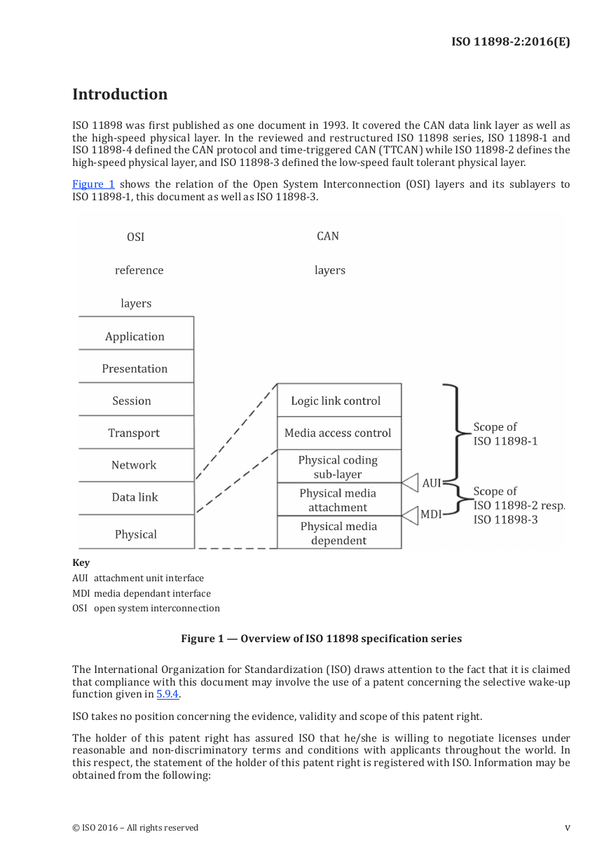
Figure 1 shows the relation of the Open System Interconnection (OSI) layers and its sublayers to
ISO 11898-1, this document as well as ISO 11898-3.
Figure 1 — Overview of ISO 11898 specification series
KeyAUI attachment unit interface
MDImedia dependant interface
OSI open system interconnection
The International Organization for Standardization (ISO) draws attention to the fact that it is claimed
that compliance with this document may involve the use of a patent concerning the selective wake-up
function given in 5.9.4.
ISO takes no position concerning the evidence, validity and scope of this patent right.
The holder of this patent right has assured ISO that he/she is willing to negotiate licenses under
reasonable and non-discriminatory terms and conditions with applicants throughout the world. In
this respect, the statement of the holder of this patent right is registered with ISO. Information may be
obtained from the following:
v
© ISO 2016 – All rights reserved
�
ISO 11898-2:2016(E)
Elmos Semiconductor AG
Heinrich-Hertz-Str. 1
44227 Dortmund
Germany
Freescale Semiconductor Inc.
6501 W. William Canon Drive
Austin, Texas
United States
General Motors Corp.
30001 VanDyke, Bldg 2-10
Warren, MI 48090-9020
United States of America
NXP BV
High Tech Campus 60
5656 AG Eindhoven
The Netherlands
Audi AG
August-Horch-Str.
85045 Ingolstadt
Germany
BMW Group
Knorrstr. 147
80788 München
Germany
Continental Teves AG & Co. oHG
Guerickestr. 7
60488 Frankfurt am Main
Germany
DENSO CORP.
1-1, Showa-cho, Kariya-shi
Aichi-ken 448-8661
Japan
Attention is drawn to the possibility that some of the elements of this document may be the subject of
patent rights other than those identified above. ISO shall not be held responsible for identifying any
or all such patent rights. ISO (www.iso.org/patents) maintains on-line databases of patents relevant
to their standards. Users are encouraged to consult the databases for the most up to date information
concerning patents.
Renesas Electronics Europe GmbH
Arcadiastr. 10
40472 Düsseldorf
Germany
Robert Bosch GmbH
PO Box 30 02 20
70442 Stuttgart
Germany
STMicroelectronics Application
GmbH
Bahnhofstrasse 18
85609 Aschheim Dornach
Germany
Volkswagen AG
PO Box 011/1770
38436 Wolfsburg
Germany
vi
© ISO 2016 – All rights reserved
�
INTERNATIONAL STANDARD
ISO 11898-2:2016(E)
1 Scope
2 Normative references
signalling
3 Terms and definitions
medium access unit with selective wake-up functionality
High-speed medium access unit
Road vehicles — Controller area network (CAN) —
Part 2:
This document specifies the high-speed physical media attachment (HS-PMA) of the controller area
network (CAN), a serial communication protocol that supports distributed real-time control and
multiplexing for use within road vehicles. This includes HS-PMAs without and with low-power mode
capability as well as with selective wake-up functionality. The physical media dependant sublayer is
not in the scope of this document.
The following documents are referred to in the text in such a way that some or all of their content
constitutes requirements of this document. For dated references, only the edition cited applies. For
undated references, the latest edition of the referenced document (including any amendments) applies.
ISO 11898-1:2015, Road vehicles — Controller area network (CAN) — Part 1: Data link layer and physical
ISO 16845-2, Road vehicles — Controller area network (CAN) conformance test plan — Part 2: High-speed
For the purposes of this document, the terms and definitions given in ISO 11898-1 and the following apply.
ISO and IEC maintain terminological databases for use in standardization at the following addresses:
— IEC Electropedia: available at http://www.electropedia.org/
— ISO Online browsing platform: available at http://www.iso.org/obp
NOTE
interface between the PCS that is specified in ISO 11898-1 and the PMA that is specified in this document
GNDelectrical signal ground
HS-PMA implementation that has been released prior to the publication of this document
© ISO 2016 – All rights reserved
See Figure A.1 for a visualization of the definitions.
3.1
attachment unit interface
AUI
3.2
ground
3.3
legacy implementation
1
�
ISO 11898-2:2016(E)
3.4
low-power mode
3.5
medium attachment unit
3.10
transceiver
4 Symbols and abbreviated terms
3.9
physical media attachment
3.7
normal-power mode
3.8
physical coding sublayer
3.6
media dependent interface
MDI
mode in which the transceiver is not capable of transmitting or receiving messages, except for the
purposes of determining if a WUP or WUF is being received
MAUunit that comprises the physical media attachment and the media dependent interface
interface that ensures proper signal transfer between the media and the physical media attachment
mode in which the transceiver is fully capable of transmitting and receiving messages
PCSsublayer that performs bit encoding/decoding and synchronization
PMAsublayer that converts physical signals into logical signals and vice versa
implementation that comprises one or more physical media attachments
For the purposes of this document, the symbols and abbreviated terms given in ISO 11898-1 and the
following apply. Some of these abbreviations are also defined in ISO 11898-1. If the definition of the
term in this document is different from the definition in ISO 11898-1, this definition applies.
AUI
DLC
EMC
ESD
GND
HS-PMA
MAU
MDI
PCS
PMA
attachment unit interface
data length code
electromagnetic compatibility
electro static discharge
ground
high-speed PMA
medium attachment unit
media dependent interface
physical coding sublayer
physical media attachment
2
© ISO 2016 – All rights reserved
�


 2023年江西萍乡中考道德与法治真题及答案.doc
 2012年重庆南川中考生物真题及答案.doc
 2013年江西师范大学地理学综合及文艺理论基础考研真题.doc
 2020年四川甘孜小升初语文真题及答案I卷.doc
 2020年注册岩土工程师专业基础考试真题及答案.doc
 2023-2024学年福建省厦门市九年级上学期数学月考试题及答案.doc
 2021-2022学年辽宁省沈阳市大东区九年级上学期语文期末试题及答案.doc
 2022-2023学年北京东城区初三第一学期物理期末试卷及答案.doc
 2018上半年江西教师资格初中地理学科知识与教学能力真题及答案.doc
 2012年河北国家公务员申论考试真题及答案-省级.doc
 2020-2021学年江苏省扬州市江都区邵樊片九年级上学期数学第一次质量检测试题及答案.doc
 2022下半年黑龙江教师资格证中学综合素质真题及答案.doc