Document No.05-081205 FBG Interrogation Analyzer User Manual Rev.3.5
FBG Interrogation Analyzer
User Manual Version 3.5
3
1.
2.
Table of Contents:
Introduction
FBG Analyzer Electrical Specifications
2.1 Electrical Configuration
2.2 Pin Definition
2.3 DC Electrical Specifications
2.4 AC Electrical Specifications
2.5 Timing Diagrams
Software Interface
3.1
Introduction
3.2 Direct Interface
3.3 Dual Port RAM
3.4 Output Data Description
3.5 RS232 Interface Commands
3.6 Using the USB Interface
OSADataTypes.h
VOSE32.h
4
5
6 Mechanical Drawings
7 Other Information
1
4
4
5
7
7
8
10
10
10
15
19
21
22
23
27
29
30
BaySpec, Inc.
101 Hammond Avenue, Fremont, CA 94539
Tel. (510) 661 2008 • Fax: (510) 661 2009 • Web: www.bayspec.com
November 2006
BaySpec, Inc.
© Copyright to BaySpec, Inc. 2002-2006
Document subject to alterations without notice
November 2006
�
Document No.05-081205 FBG Interrogation Analyzer User Manual Rev.3.5
This FBG Interrogation Analyzer User Manual contains FBG hardware, FBG software,
OSADataTypes file, and typical mechanical drawings. It applies to WaveCapture® FBG
Interrogation Analyzers and other relevant spectral monitoring products. In the following, the
term of “FBG Analyzer” will be used for simplicity of description.
1. Introduction
BaySpec's WaveCapture® FBG sensing products are integrated spectral engines embracing the
essential functions of optical wavelength meter, optical power meter and optical spectrum
analyzer, providing rapid wavelength, power and OSNR measurements. From these
measurements, one can quickly identify channels and derive channel wavelength shifts, channel
power distribution, and other critical health monitoring information.
Providing a quick and accurate measurement of wavelength, power and OSNR of optical
signals with a minature device in both DWDM and CWDM evrironments is challenging work.
Desktop Optical Spectrum Analyzers (OSA) can do the job, but they are not suitable for
integrating with communications systems and field inspections. The field test and system
monitoring of fiber-optic communications networks requires compact size, low power
consumption, high speed, high repeatability, and high reliability. WaveCapture® series
spectral monitoring products are designed and manufactured to simultaneously meet these
critical requirements. BaySpec offers the world-smallest FBG Analyzers using high-resolution
volume phase grating (VPG®) technology and high-efficiency InGaAs array detector.
The basic operating diagram for
the FBG Analyzer module
is
schematically shown in Figure 1.
The input light signal coming from
a communications network or
collected from the sample under
test
incident on a beam-
collimating lens through an optical
interface. The collimated
fiber
beam
is
the
spectral element
from
which
the different wavelength
components are separated. These
angularly
beams
(wavelength components) are then
focused onto a photodiode array by
a focusing lens. Thus, the light
signals at different wavelengths are
measured
into
electrical signals. The electrical outputs are subsequently transmitted to the electronics circuitry
for processing and output, from which spectral information is obtained. Figure 2 shows a
photograph of the FBG Analyzer.
Fig. 1: Schematic diagram for FBG Analyzer module.
Detector
Detector
Array
Array
then directed
to
and
converted
Output
Output
To host
To host
(VPG),
dispersed
is
Input
Input
VPG
VPG
Electronics
Electronics
BaySpec, Inc.
© Copyright to BaySpec, Inc. 2002-2006
Document subject to alterations without notice
- 1 -
November 2006
�
Document No.05-081205 FBG Interrogation Analyzer User Manual Rev.3.5
Fig. 2: Photo of WaveCapture® FBG Interrogation Analyzer
WaveCapture® FBG Interrogation Analyzer can not only stand alone as a miniature
spectrometer module using its own high-speed electronics and embedded software, but also can
be used as an integrated spectral element in handheld/portable Optical Spectrum Analyzers
(OSA). These applications, not limited to, include:
• Fiber bragg grating interrogation analysis in smart structures, oil/gas exploration
equipment, aerospace/aeronautics, etc.
• Real-time optical performance monitoring of DWDM networks
• Optical add/drop monitoring and diagnostics
• Remote gain equalization of DWDM systems based on optical power or OSNR
• Transmission laser wavelength locking
• Real-time system error warning and alarming
• EDFA gain balancing
• Handheld/portable Optical Spectrum Analyzers
The FBG Analyzer offer the following distinct features and benefits:
• Small size – Give more flexibility to integrate it into customers’ systems. BaySpec
provides the world-smallest FBG Analyzer for OEM applications.
• Low cost – Innovative design and high production yield make the products at low cost.
It is afordable and cost effective.
• Athermal – Without the need of active temperature control over the operating
temperature range. This results in extremely low power consumption.
• High-speed – The module utilizes parallel detection and fast electronics. The devices
operate independent of data rate and protocol.
• Custom design – Customer can tailor the requirements for measurements to optimize
optical and electric performance and minimize cost.
• No moving parts – This greatly increases reliability of the devices and repeatability of
measurements. Furthermore, no re-calibration is required. This, along with athermal
operation, makes the FBG Analyzer perfectly suitable for field use.
BaySpec, Inc.
© Copyright to BaySpec, Inc. 2002-2006
Document subject to alterations without notice
- 2 -
November 2006
�
Document No.05-081205 FBG Interrogation Analyzer User Manual Rev.3.5
• Hermetic packaging – Device can work in various rough environment.
•
Fiber-optic interface – Single or multi-mode fiber interface facilitates optical connection
and keeps high coupling efficiency
• RS232/USB/Parallel interface – Multiple options for electric interface a
• Software upgradeable.
re available.
For mo
re information, please contact BaySpec Applications Support team.
BaySpec, Inc.
© Copyright to BaySpec, Inc. 2002-2006
Document subject to alterations without notice
- 3 -
November 2006
�
ADDRESS BUS
CONTROL
DATA BUS
RS 232
FBG
Analyzer
USB
+ 5 V
G.P.I.O.
HOST
COMPUTER
Document No.05-081205 FBG Interrogation Analyzer User Manual Rev.3.5
2. FBG Interrogation Analyzer Electrical Specifications
2.1 Electrical Configuration
The FBG Analyzer is connected to the host computer through a 50-pin connector. Figure 3
shows all signals between the FBG Analyzer and a host computer.
Fig. 3: Electrical connections of the FBG Analyzer to a host computer.
Data Bus:
Address Bus:
16-bit wide bi-directional data bus.
12-bit wide address lines to access the dual-port memory in the FBG
Analyzer.
Control signals: Directly connected communication lines for fast response.
GPIO:
General-purpose I/O lines to provide communications with fast response.
It can be customized by the user.
Serial communication port.
Serial communication port.
RS 232:
USB:
BaySpec, Inc.
© Copyright to BaySpec, Inc. 2002-2006
Document subject to alterations without notice
- 4 -
November 2006
�
Document No.05-081205 FBG Interrogation Analyzer User Manual Rev.3.5
2.2 Pin definition
FBG Analyzer pin definition and assignment are given in Table 1 and Figure 4.
Table 1. Pin assignment.
Pin Name
1
2
3
4
5
6
7
8
9
10
11
12
13
14
15
D0
D1
D2
D3
D4
D5
D6
D7
D8
D9
D10
D11
D12
D13
D14
16
17
D15
R/W
18
19
20
21
22
23
24
25
/CS
A0
A1
A2
A3
A4
A5
A6
/RESET
/CMD_RDY
/DATA_RDY
/ERROR
/CS
R /W
Description
I/O
I/O Data (LSB)
I/O
I/O
I/O
I/O
I/O
I/O
I/O
I/O
I/O
I/O
I/O
I/O
I/O
I/O
I/O Data (MSB)
I
I
I
I
I
I
I
I
I
Read / write
Chip select
Address
Pin
Name
26 A7
27 A8
28 A9
29 A10
30 A11
/DAT_RDY
31
/ERR
32
33
INT/GPIO2
34 Reserved
35 Reserved
36
/CMD_RDY
37 Reserved
38 Reserved
39
40 Reserved
/RESET
41 AVCC
42 AVCC
43 VCC
44 AGND
45 DGND
46 DGND
47 USB D+
48 USB D-
49 RXD
50 TXD
Description
I/O
I
I
I
I
I
O Data ready from device
O Error from device
I/O Reserved
O Reserved
Reserved
I
I
Command ready from host
O Reserved
O Reserved
I
I
Reset
Reserved
3V - 5V Power Supply
(analog) (optional)
3V - 5V Power Supply
(analog) (optional)
3V – 5V Power Supply
(digital)
PWR
PWR
PWR
PWR Analog Ground
PWR Digital Ground
PWR Digital Ground
I/O USB serial port
I/O
I
O
RS232 serial port
Hardware reset/shutdown line.
Command is ready for the unit.
Data is ready for the host to read.
Command received by the unit has error.
The unit is selected by the host.
Read or write from the host.
BaySpec, Inc.
© Copyright to BaySpec, Inc. 2002-2006
Document subject to alterations without notice
- 5 -
November 2006
�
Document No.05-081205 FBG Interrogation Analyzer User Manual Rev.3.5
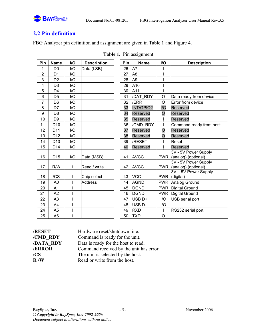
Fig. 4(a): 50-pin right angle connector mechanical dimensions.
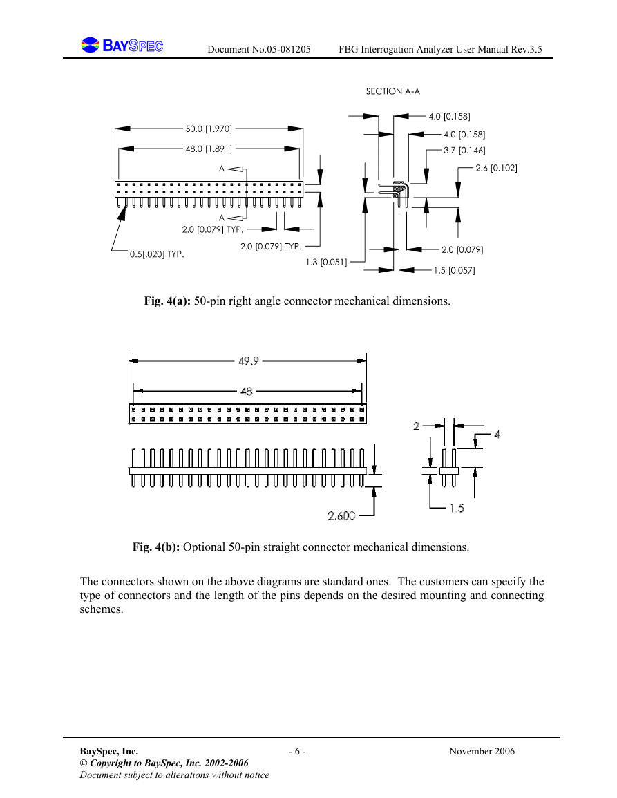
Fig. 4(b): Optional 50-pin straight connector mechanical dimensions.
The connectors shown on the above diagrams are standard ones. The customers can specify the
type of connectors and the length of the pins depends on the desired mounting and connecting
schemes.
BaySpec, Inc.
© Copyright to BaySpec, Inc. 2002-2006
Document subject to alterations without notice
- 6 -
November 2006
�
Document No.05-081205 FBG Interrogation Analyzer User Manual Rev.3.5
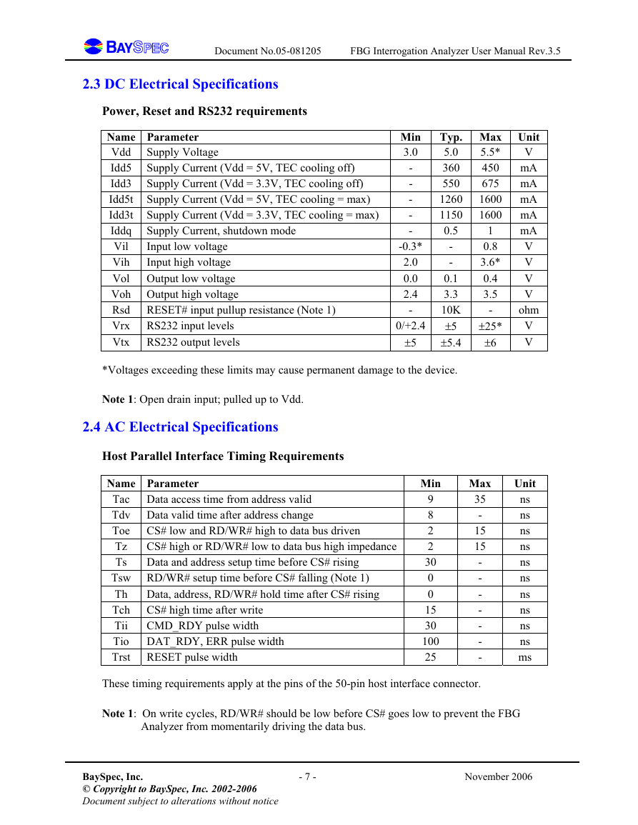
2.3 DC Electrical Specifications
Power, Reset and RS232 requirements
Supply Voltage
Name Parameter
Vdd
Idd5 Supply Current (Vdd = 5V, TEC cooling off)
Idd3 Supply Current (Vdd = 3.3V, TEC cooling off)
Idd5t Supply Current (Vdd = 5V, TEC cooling = max)
Idd3t Supply Current (Vdd = 3.3V, TEC cooling = max)
Iddq Supply Current, shutdown mode
Input low voltage
Vil
Vih
Input high voltage
Vol Output low voltage
Voh Output high voltage
Rsd RESET# input pullup resistance (Note 1)
Vrx RS232 input levels
Vtx RS232 output levels
Min
3.0
-
-
-
-
-
-0.3*
2.0
0.0
2.4
-
0/+2.4
±5
Typ. Max Unit
5.0
V
5.5*
mA
360
450
550
mA
675
1600 mA
1260
1600 mA
1150
0.5
mA
V
-
V
-
V
0.1
3.3
V
ohm
10K
V
±5
V
±5.4
1
0.8
3.6*
0.4
3.5
-
±25*
±6
*Voltages exceeding these limits may cause permanent damage to the device.
Note 1: Open drain input; pulled up to Vdd.
2.4 AC Electrical Specifications
Host Parallel Interface Timing Requirements
CS# high or RD/WR# low to data bus high impedance
Data and address setup time before CS# rising
Name Parameter
Tac Data access time from address valid
Tdv Data valid time after address change
Toe CS# low and RD/WR# high to data bus driven
Tz
Ts
Tsw RD/WR# setup time before CS# falling (Note 1)
Th Data, address, RD/WR# hold time after CS# rising
Tch CS# high time after write
Tii
CMD_RDY pulse width
Tio DAT_RDY, ERR pulse width
Trst RESET pulse width
Min
9
8
2
2
30
0
0
15
30
100
25
Max
35
-
15
15
-
-
-
-
-
-
-
Unit
ns
ns
ns
ns
ns
ns
ns
ns
ns
ns
ms
These timing requirements apply at the pins of the 50-pin host interface connector.
Note 1: On write cycles, RD/WR# should be low before CS# goes low to prevent the FBG
Analyzer from momentarily driving the data bus.
BaySpec, Inc.
© Copyright to BaySpec, Inc. 2002-2006
Document subject to alterations without notice
- 7 -
November 2006
�





 2023年江西萍乡中考道德与法治真题及答案.doc
 2012年重庆南川中考生物真题及答案.doc
 2013年江西师范大学地理学综合及文艺理论基础考研真题.doc
 2020年四川甘孜小升初语文真题及答案I卷.doc
 2020年注册岩土工程师专业基础考试真题及答案.doc
 2023-2024学年福建省厦门市九年级上学期数学月考试题及答案.doc
 2021-2022学年辽宁省沈阳市大东区九年级上学期语文期末试题及答案.doc
 2022-2023学年北京东城区初三第一学期物理期末试卷及答案.doc
 2018上半年江西教师资格初中地理学科知识与教学能力真题及答案.doc
 2012年河北国家公务员申论考试真题及答案-省级.doc
 2020-2021学年江苏省扬州市江都区邵樊片九年级上学期数学第一次质量检测试题及答案.doc
 2022下半年黑龙江教师资格证中学综合素质真题及答案.doc