DAQ/PXI-201x/200x
4-CH, Simultaneous, High Performance
Multi-Function Data Acquisition Card
User’s Manual
2.00
Manual Rev.
Revision Date: April 20, 2006
Part No:
50-11020-1030
Advance Technologies; Automate the World.
�
Copyright 2006 ADLINK TECHNOLOGY INC.
All Rights Reserved.
The information in this document is subject to change without prior
notice in order to improve reliability, design, and function and does
not represent a commitment on the part of the manufacturer.
In no event will the manufacturer be liable for direct, indirect, spe-
cial, incidental, or consequential damages arising out of the use or
inability to use the product or documentation, even if advised of
the possibility of such damages.
This document contains proprietary information protected by copy-
right. All rights are reserved. No part of this manual may be repro-
duced by any mechanical, electronic, or other means in any form
without prior written permission of the manufacturer.
Trademarks
Product names mentioned herein are used for identification pur-
poses only and may be trademarks and/or registered trademarks
of their respective companies.
�
Getting Service from ADLINK
Customer Satisfaction is top priority for ADLINK Technology Inc.
Please contact us should you require any service or assistance.
Web Site:
Sales & Service:
TEL:
FAX:
Address:
ADLINK TECHNOLOGY INC.
http://www.adlinktech.com
Service@adlinktech.com
+886-2-82265877
+886-2-82265717
9F, No. 166, Jian Yi Road, Chungho City,
Taipei, 235 Taiwan
Please email or FAX this completed service form for prompt and
satisfactory service.
Company Information
Company/Organization
Contact Person
E-mail Address
Address
Country
TEL
Web Site
Product Model
Environment
FAX:
Product Information
OS:
M/B: CPU:
Chipset: Bios:
Please give a detailed description of the problem(s):
�
�
Table of Contents
1.1
1.2
1.3
1.4
2.1
2.2
2.3
2.4
1 Introduction ........................................................................ 1
Features............................................................................... 2
Applications ......................................................................... 3
Specifications....................................................................... 4
Software Support ............................................................... 13
Programming Library .................................................... 13
DAQ-LVIEW PnP: LabVIEW® Driver ........................... 13
D2K-OCX: ActiveX Controls ......................................... 14
2 Installation ........................................................................ 15
Contents of Package ......................................................... 15
Unpacking.......................................................................... 15
DAQ/PXI-20XX Layout ...................................................... 17
PCI Configuration .............................................................. 18
3 Signal Connections.......................................................... 19
Connectors Pin Assignment .............................................. 19
Analog Input Signal Connection ........................................ 24
Types of signal sources ................................................ 24
Single-Ended Measurements ....................................... 24
Differential Measurements ............................................ 25
4 Operation Theory ............................................................. 27
A/D Conversion.................................................................. 27
DAQ/PXI-2010 AI Data Format ..................................... 28
DAQ/PXI-2005/2006/2016 AI Data Format ................... 30
Software conversion with polling data transfer acqui-sition
mode (Software Polling) ..................................... 30
Programmable scan acquisition mode .......................... 31
Trigger Modes ............................................................... 33
D/A Conversion.................................................................. 42
Software Update ........................................................... 43
Timed Waveform Generation ........................................ 44
Trigger Modes ............................................................... 45
4.3
Digital I/O ........................................................................... 51
4.4 General Purpose Timer/Counter Operation....................... 52
Timer/Counter functions basics .................................... 52
General Purpose Timer/Counter modes ....................... 53
3.1
3.2
4.1
4.2
Table of Contents
i
�
4.5
4.6
Trigger Sources ................................................................. 57
Software-Trigger ........................................................... 57
External Analog Trigger ................................................ 57
User-controllable Timing Signals ....................................... 61
DAQ timing signals ....................................................... 63
Auxiliary Function Inputs (AFI) ...................................... 64
System Synchronization Interface ................................ 67
AI_Trig_Out and AO_Trig_Out ..................................... 69
5 Calibration ......................................................................... 71
Loading Calibration Constants........................................... 71
Auto-calibration.................................................................. 71
Saving Calibration Constants............................................. 72
5.1
5.2
5.3
ii
Table of Contents
�
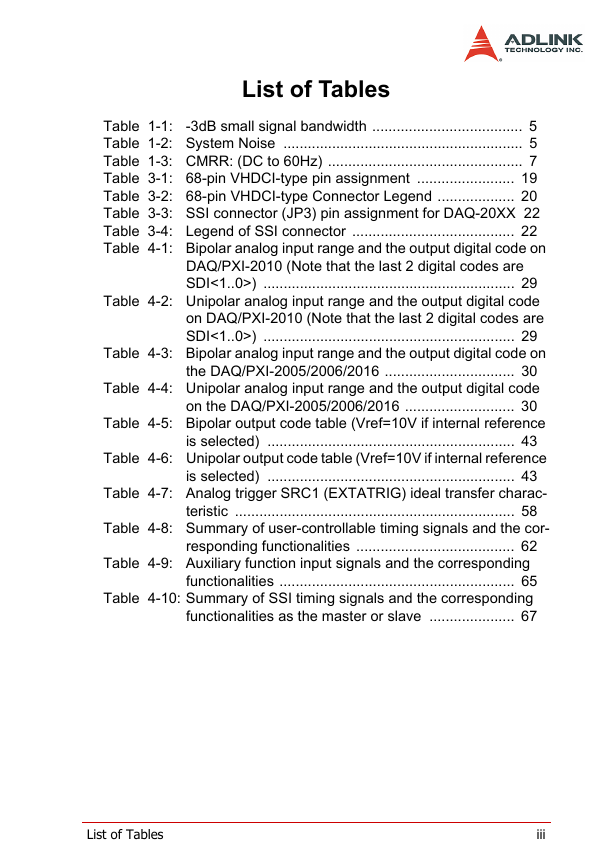
List of Tables
Table 1-1:
-3dB small signal bandwidth ..................................... 5
Table 1-2: System Noise ........................................................... 5
Table 1-3: CMRR: (DC to 60Hz) ................................................ 7
Table 3-1: 68-pin VHDCI-type pin assignment ........................ 19
Table 3-2: 68-pin VHDCI-type Connector Legend ................... 20
Table 3-3: SSI connector (JP3) pin assignment for DAQ-20XX 22
Table 3-4: Legend of SSI connector ........................................ 22
Table 4-1: Bipolar analog input range and the output digital code on
DAQ/PXI-2010 (Note that the last 2 digital codes are
SDI<1..0>) .............................................................. 29
Table 4-2: Unipolar analog input range and the output digital code
on DAQ/PXI-2010 (Note that the last 2 digital codes are
SDI<1..0>) .............................................................. 29
Table 4-3: Bipolar analog input range and the output digital code on
the DAQ/PXI-2005/2006/2016 ................................ 30
Table 4-4: Unipolar analog input range and the output digital code
on the DAQ/PXI-2005/2006/2016 ........................... 30
Table 4-5: Bipolar output code table (Vref=10V if internal reference
is selected) ............................................................. 43
Table 4-6: Unipolar output code table (Vref=10V if internal reference
is selected) ............................................................. 43
Table 4-7: Analog trigger SRC1 (EXTATRIG) ideal transfer charac-
teristic ..................................................................... 58
Table 4-8: Summary of user-controllable timing signals and the cor-
responding functionalities ....................................... 62
Table 4-9: Auxiliary function input signals and the corresponding
functionalities .......................................................... 65
Table 4-10: Summary of SSI timing signals and the corresponding
functionalities as the master or slave ..................... 67
List of Tables
iii
�
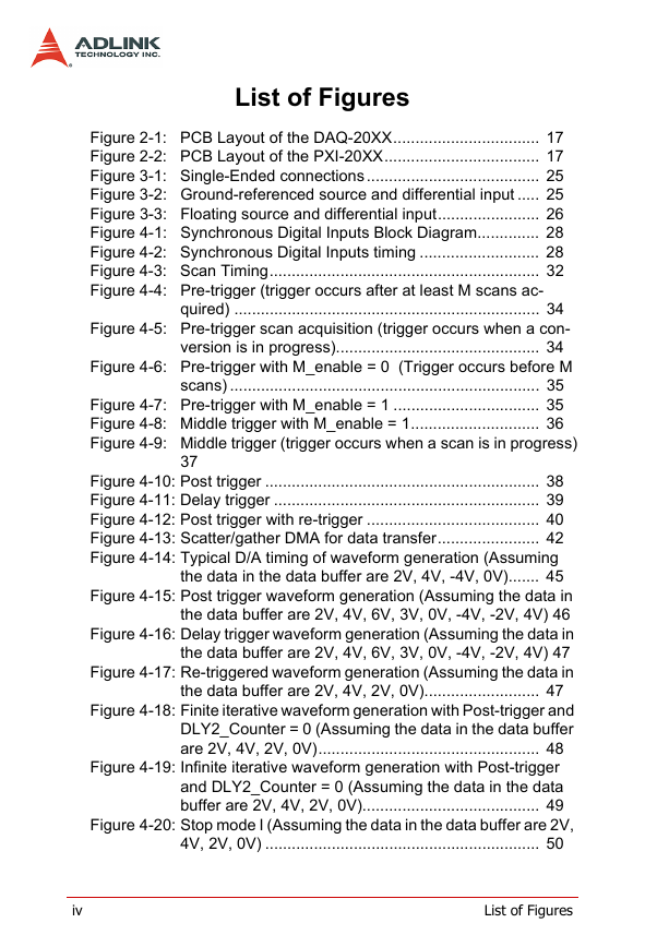
List of Figures
Figure 2-1: PCB Layout of the DAQ-20XX................................. 17
Figure 2-2: PCB Layout of the PXI-20XX................................... 17
Figure 3-1: Single-Ended connections....................................... 25
Figure 3-2: Ground-referenced source and differential input ..... 25
Figure 3-3: Floating source and differential input....................... 26
Figure 4-1: Synchronous Digital Inputs Block Diagram.............. 28
Figure 4-2: Synchronous Digital Inputs timing ........................... 28
Figure 4-3: Scan Timing............................................................. 32
Figure 4-4: Pre-trigger (trigger occurs after at least M scans ac-
quired) ..................................................................... 34
Figure 4-5: Pre-trigger scan acquisition (trigger occurs when a con-
version is in progress).............................................. 34
Figure 4-6: Pre-trigger with M_enable = 0 (Trigger occurs before M
scans) ...................................................................... 35
Figure 4-7: Pre-trigger with M_enable = 1 ................................. 35
Figure 4-8: Middle trigger with M_enable = 1............................. 36
Figure 4-9: Middle trigger (trigger occurs when a scan is in progress)
37
Figure 4-10: Post trigger .............................................................. 38
Figure 4-11: Delay trigger ............................................................ 39
Figure 4-12: Post trigger with re-trigger ....................................... 40
Figure 4-13: Scatter/gather DMA for data transfer....................... 42
Figure 4-14: Typical D/A timing of waveform generation (Assuming
the data in the data buffer are 2V, 4V, -4V, 0V)....... 45
Figure 4-15: Post trigger waveform generation (Assuming the data in
the data buffer are 2V, 4V, 6V, 3V, 0V, -4V, -2V, 4V) 46
Figure 4-16: Delay trigger waveform generation (Assuming the data in
the data buffer are 2V, 4V, 6V, 3V, 0V, -4V, -2V, 4V) 47
Figure 4-17: Re-triggered waveform generation (Assuming the data in
the data buffer are 2V, 4V, 2V, 0V).......................... 47
Figure 4-18: Finite iterative waveform generation with Post-trigger and
DLY2_Counter = 0 (Assuming the data in the data buffer
are 2V, 4V, 2V, 0V).................................................. 48
Figure 4-19: Infinite iterative waveform generation with Post-trigger
and DLY2_Counter = 0 (Assuming the data in the data
buffer are 2V, 4V, 2V, 0V)........................................ 49
Figure 4-20: Stop mode I (Assuming the data in the data buffer are 2V,
4V, 2V, 0V) .............................................................. 50
iv
List of Figures
�




 2023年江西萍乡中考道德与法治真题及答案.doc
 2012年重庆南川中考生物真题及答案.doc
 2013年江西师范大学地理学综合及文艺理论基础考研真题.doc
 2020年四川甘孜小升初语文真题及答案I卷.doc
 2020年注册岩土工程师专业基础考试真题及答案.doc
 2023-2024学年福建省厦门市九年级上学期数学月考试题及答案.doc
 2021-2022学年辽宁省沈阳市大东区九年级上学期语文期末试题及答案.doc
 2022-2023学年北京东城区初三第一学期物理期末试卷及答案.doc
 2018上半年江西教师资格初中地理学科知识与教学能力真题及答案.doc
 2012年河北国家公务员申论考试真题及答案-省级.doc
 2020-2021学年江苏省扬州市江都区邵樊片九年级上学期数学第一次质量检测试题及答案.doc
 2022下半年黑龙江教师资格证中学综合素质真题及答案.doc