GigaDevice Semiconductor Inc.
GD32F205xx
ARM® Cortex®-M3 32-bit MCU
Datasheet
�
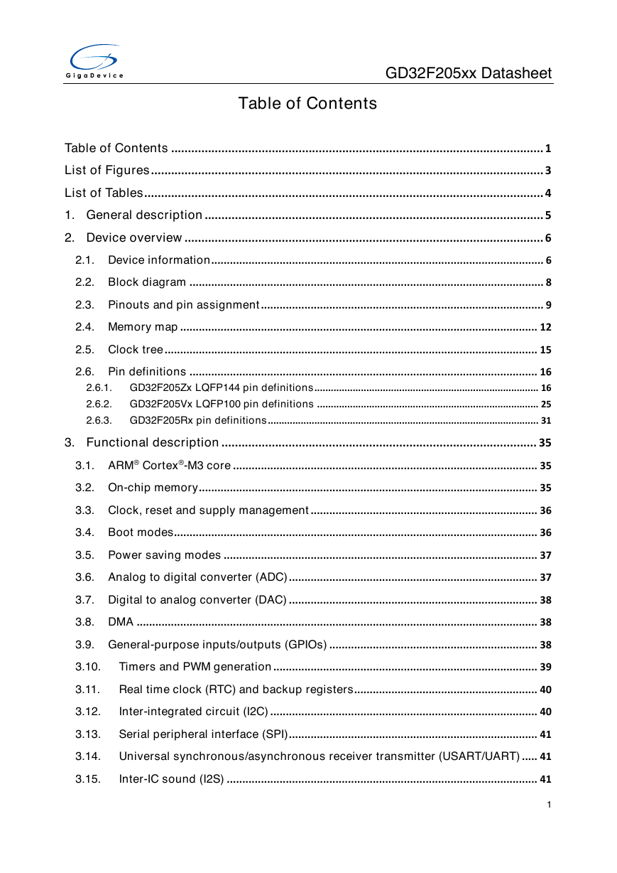
GD32F205xx Datasheet
Table of Contents
Table of Contents ............................................................................................................... 1
List of Figures ..................................................................................................................... 3
List of Tables ....................................................................................................................... 4
1. General description ..................................................................................................... 5
2. Device overview ........................................................................................................... 6
2.1. Device information ........................................................................................................... 6
2.2. Block diagram .................................................................................................................. 8
2.3. Pinouts and pin assignment ........................................................................................... 9
2.4. Memory map ................................................................................................................... 12
2.5. Clock tree ........................................................................................................................ 15
2.6. Pin definitions ................................................................................................................ 16
2.6.1. GD32F205Zx LQFP144 pin definitions .................................................................................. 16
2.6.2. GD32F205Vx LQFP100 pin definitions ................................................................................. 25
2.6.3. GD32F205Rx pin definitions ................................................................................................... 31
3. Functional description .............................................................................................. 35
3.1. ARM® Cortex®-M3 core .................................................................................................. 35
3.2. On-chip memory ............................................................................................................. 35
3.3. Clock, reset and supply management ......................................................................... 36
3.4. Boot modes..................................................................................................................... 36
3.5. Power saving modes ..................................................................................................... 37
3.6. Analog to digital converter (ADC) ................................................................................ 37
3.7. Digital to analog converter (DAC) ................................................................................ 38
3.8. DMA ................................................................................................................................. 38
3.9. General-purpose inputs/outputs (GPIOs) ................................................................... 38
3.10.
Timers and PWM generation ..................................................................................... 39
3.11. Real time clock (RTC) and backup registers ........................................................... 40
3.12.
Inter-integrated circuit (I2C) ...................................................................................... 40
3.13.
Serial peripheral interface (SPI) ................................................................................ 41
3.14. Universal synchronous/asynchronous receiver transmitter (USART/UART) ..... 41
3.15.
Inter-IC sound (I2S) .................................................................................................... 41
1
�
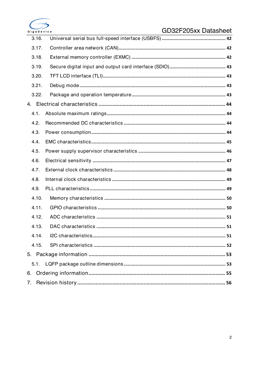
GD32F205xx Datasheet
3.16. Universal serial bus full-speed interface (USBFS) ................................................. 42
3.17. Controller area network (CAN) .................................................................................. 42
3.18.
External memory controller (EXMC) ........................................................................ 42
3.19.
Secure digital input and output card interface (SDIO) ........................................... 43
3.20.
TFT LCD interface (TLI) .............................................................................................. 43
3.21. Debug mode ................................................................................................................ 43
3.22.
Package and operation temperature ........................................................................ 43
4. Electrical characteristics .......................................................................................... 44
4.1. Absolute maximum ratings ........................................................................................... 44
4.2. Recommended DC characteristics .............................................................................. 44
4.3. Power consumption ....................................................................................................... 44
4.4. EMC characteristics ....................................................................................................... 45
4.5. Power supply supervisor characteristics ................................................................... 46
4.6. Electrical sensitivity ...................................................................................................... 47
4.7. External clock characteristics ...................................................................................... 48
4.8.
Internal clock characteristics ....................................................................................... 49
4.9. PLL characteristics ........................................................................................................ 49
4.10. Memory characteristics ............................................................................................. 50
4.11. GPIO characteristics .................................................................................................. 50
4.12. ADC characteristics ................................................................................................... 51
4.13. DAC characteristics ................................................................................................... 51
4.14.
I2C characteristics ...................................................................................................... 51
4.15.
SPI characteristics ..................................................................................................... 52
5. Package information ................................................................................................. 53
5.1. LQFP package outline dimensions .............................................................................. 53
6. Ordering information ................................................................................................. 55
7. Revision history ......................................................................................................... 56
2
�
GD32F205xx Datasheet
List of Figures
Figure 2-1. GD32F205xx block diagram ......................................................................................................... 8
Figure 2-2. GD32F205Zx LQFP144 pinouts.................................................................................................... 9
Figure 2-3. GD32F205Vx LQFP100 pinouts ................................................................................................. 10
Figure 2-4. GD32F205Rx LQFP64 pinouts ................................................................................................... 11
Figure 2-5. GD32F205xx clock tree ............................................................................................................... 15
Figure 5-1. LQFP package outline ................................................................................................................. 53
3
�
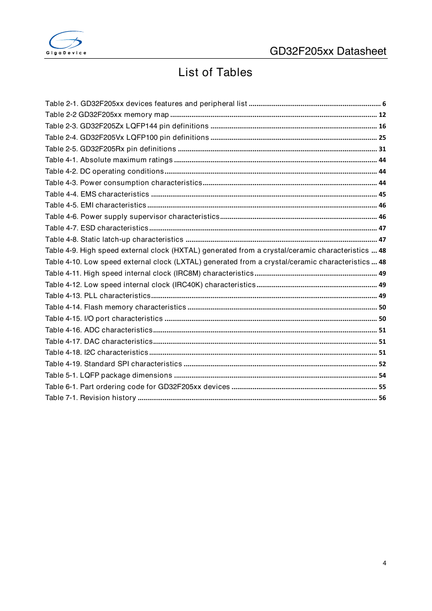
GD32F205xx Datasheet
List of Tables
Table 2-1. GD32F205xx devices features and peripheral list ..................................................................... 6
Table 2-2 GD32F205xx memory map ............................................................................................................ 12
Table 2-3. GD32F205Zx LQFP144 pin definitions ....................................................................................... 16
Table 2-4. GD32F205Vx LQFP100 pin definitions ....................................................................................... 25
Table 2-5. GD32F205Rx pin definitions ........................................................................................................ 31
Table 4-1. Absolute maximum ratings .......................................................................................................... 44
Table 4-2. DC operating conditions ............................................................................................................... 44
Table 4-3. Power consumption characteristics ........................................................................................... 44
Table 4-4. EMS characteristics ...................................................................................................................... 45
Table 4-5. EMI characteristics ........................................................................................................................ 46
Table 4-6. Power supply supervisor characteristics.................................................................................. 46
Table 4-7. ESD characteristics ....................................................................................................................... 47
Table 4-8. Static latch-up characteristics .................................................................................................... 47
Table 4-9. High speed external clock (HXTAL) generated from a crystal/ceramic characteristics ... 48
Table 4-10. Low speed external clock (LXTAL) generated from a crystal/ceramic characteristics ... 48
Table 4-11. High speed internal clock (IRC8M) characteristics ................................................................ 49
Table 4-12. Low speed internal clock (IRC40K) characteristics ............................................................... 49
Table 4-13. PLL characteristics ...................................................................................................................... 49
Table 4-14. Flash memory characteristics ................................................................................................... 50
Table 4-15. I/O port characteristics ............................................................................................................... 50
Table 4-16. ADC characteristics..................................................................................................................... 51
Table 4-17. DAC characteristics..................................................................................................................... 51
Table 4-18. I2C characteristics ....................................................................................................................... 51
Table 4-19. Standard SPI characteristics ..................................................................................................... 52
Table 5-1. LQFP package dimensions .......................................................................................................... 54
Table 6-1. Part ordering code for GD32F205xx devices ............................................................................ 55
Table 7-1. Revision history ............................................................................................................................. 56
4
�
GD32F205xx Datasheet
1.
General description
The GD32F205xx device belongs to the performance line of GD32 MCU Family. It is a new
32-bit general-purpose microcontroller based on the ARM® Cortex®-M3 RISC core with best
cost-performance ratio in terms of processing capacity, reduced power consumption and
peripheral set. The Cortex®-M3 is a next generation processor core which is tightly coupled
with a Nested Vectored Interrupt Controller (NVIC), SysTick timer and advanced debug
support.
The GD32F205xx device incorporates the ARM® Cortex®-M3 32-bit processor core operating
at 120 MHz frequency with flash accesses zero wait states to obtain maximum efficiency. It
provides up to 3072 KB on-chip flash memory and 256 KB SRAM memory. An extensive
range of enhanced I/Os and peripherals connected to two APB buses. The devices offer up
to three 12-bit 2 MSPS ADCs, two 12-bit DACs, up to ten 16-bit general timers, two 16-bit
basic timers plus two 16-bit PWM advanced timers, as well as standard and advanced
communication interfaces: up to three SPIs, three I2Cs, four USARTs and four UARTs, two
I2Ss, two CANs, a SDIO, a USBFS. Additional peripherals as TFT-LCD Interface (TLI) and
EXMC interface with SDRAM extension support are included.
The device operates from a 2.6 to 3.6V power supply and available in –40 to +85 °C
temperature range. Several power saving modes provide the flexibility for maximum
optimization of power consumption, an especially important consideration in low power
applications.
The above features make GD32F205xx devices suitable for a wide range of interconnection
and advanced applications, especially in areas such as industrial control, consumer and
handheld equipment, embedded modules, human machine interface, security and alarm
systems, automotive navigation and so on.
5
�
GD32F205xx Datasheet
2.
Device overview
2.1.
Device information
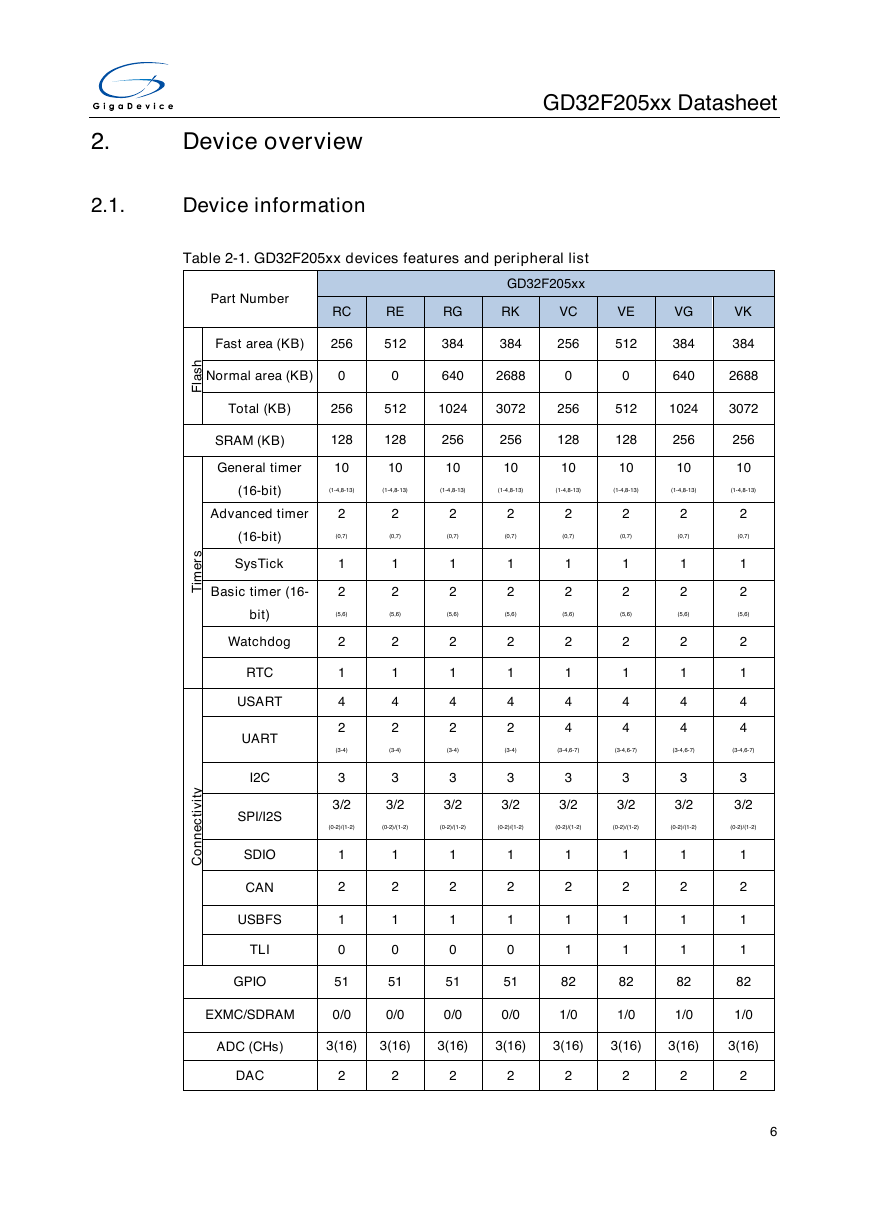
Table 2-1. GD32F205xx devices features and peripheral list
Part Number
RC
RE
RG
RK
VC
VE
VG
VK
GD32F205xx
Fast area (KB)
256
512
384
384
256
512
384
384
Normal area (KB)
0
0
640
2688
0
0
640
2688
Total (KB)
256
512
1024
3072
256
512
1024
3072
SRAM (KB)
128
128
256
256
128
128
256
256
General timer
10
10
10
10
10
10
10
(16-bit)
(1-4,8-13)
(1-4,8-13)
(1-4,8-13)
(1-4,8-13)
(1-4,8-13)
(1-4,8-13)
(1-4,8-13)
h
s
a
l
F
s
r
e
m
T
i
y
t
i
v
i
t
c
e
n
n
o
C
Advanced timer
(16-bit)
SysTick
Basic timer (16-
bit)
Watchdog
RTC
USART
UART
I2C
SPI/I2S
SDIO
CAN
USBFS
TLI
2
(0,7)
1
2
(5,6)
2
1
4
4
2
(0,7)
1
2
(5,6)
2
1
4
4
2
(0,7)
1
2
(5,6)
2
1
4
4
10
(1-4,8-13)
2
(0,7)
1
2
(5,6)
2
1
4
4
2
(0,7)
1
2
(5,6)
2
1
4
2
(3-4)
3
2
(0,7)
1
2
(5,6)
2
1
4
2
(3-4)
3
2
(0,7)
1
2
(5,6)
2
1
4
2
(3-4)
3
2
(0,7)
1
2
(5,6)
2
1
4
2
(3-4)
3
(3-4,6-7)
(3-4,6-7)
(3-4,6-7)
(3-4,6-7)
3
3
3
3
3/2
3/2
(0-2)/(1-2)
(0-2)/(1-2)
3/2
(0-2)/(1-2)
3/2
(0-2)/(1-2)
3/2
(0-2)/(1-2)
3/2
(0-2)/(1-2)
3/2
(0-2)/(1-2)
3/2
(0-2)/(1-2)
1
2
1
0
1
2
1
0
1
2
1
0
1
2
1
0
1
2
1
1
1
2
1
1
1
2
1
1
1
2
1
1
GPIO
51
51
51
51
82
82
82
82
EXMC/SDRAM
0/0
0/0
0/0
0/0
1/0
1/0
1/0
1/0
ADC (CHs)
3(16)
3(16)
3(16)
3(16)
3(16)
3(16)
3(16)
3(16)
DAC
2
2
2
2
2
2
2
2
6
�
GD32F205xx Datasheet
Part Number
RC
RE
RG
RK
VC
VE
VG
VK
GD32F205xx
Package
LQFP64
LQFP100
Table 2-1. GD32F205xx devices features and peripheral list (continued)
GD32F205xx
h
s
a
l
F
s
r
e
m
T
i
y
t
i
v
i
t
c
e
n
n
o
C
Part Number
Code area (KB)
Data area (KB)
Total (KB)
SRAM (KB)
General timer (16-
bit)
Advanced timer
(16-bit)
SysTick
Basic timer (16-
bit)
Watchdog(16-bit)
RTC
USART
UART
I2C
SPI/I2S
SDIO
CAN
USBFS
TLI
GPIO
EXMC/SDRAM
ADC (CHs)
DAC
Package
ZC
256
0
256
128
10
(1-4,8-13)
2
(0,7)
1
2
(5,6)
2
1
4
4
3
3/2
(0-2)/(1-2)
1
2
1
1
114
1/1
3(24)
2
ZE
512
0
512
128
10
(1-4,8-13)
2
(0,7)
1
2
(5,6)
2
1
4
4
3
3/2
(0-2)/(1-2)
1
2
1
1
114
1/1
3(24)
2
ZG
384
640
1024
256
10
(1-4,8-13)
2
(0,7)
1
2
(5,6)
2
1
4
4
3
3/2
(0-2)/(1-2)
1
2
1
1
114
1/1
3(24)
2
ZK
384
2688
3072
256
10
(1-4,8-13)
2
(0,7)
1
2
(5,6)
2
1
4
4
3
3/2
(0-2)/(1-2)
1
2
1
1
114
1/1
3(24)
2
LQFP144
7
�




 2023年江西萍乡中考道德与法治真题及答案.doc
 2012年重庆南川中考生物真题及答案.doc
 2013年江西师范大学地理学综合及文艺理论基础考研真题.doc
 2020年四川甘孜小升初语文真题及答案I卷.doc
 2020年注册岩土工程师专业基础考试真题及答案.doc
 2023-2024学年福建省厦门市九年级上学期数学月考试题及答案.doc
 2021-2022学年辽宁省沈阳市大东区九年级上学期语文期末试题及答案.doc
 2022-2023学年北京东城区初三第一学期物理期末试卷及答案.doc
 2018上半年江西教师资格初中地理学科知识与教学能力真题及答案.doc
 2012年河北国家公务员申论考试真题及答案-省级.doc
 2020-2021学年江苏省扬州市江都区邵樊片九年级上学期数学第一次质量检测试题及答案.doc
 2022下半年黑龙江教师资格证中学综合素质真题及答案.doc