RGM-3600 Operational Manual
RGM-3600 Operational Manual
Version 1.2
2008/05/02
This document contains information highly confidential to RoyalTek Company
LTD (RoyalTek). It is provided for the sole purpose of the business discussions
between supplier and RoyalTek and is covered under the terms of the
applicable Non-Disclosure Agreements. Disclosure of this information to other
parties is prohibited without the written consent of RoyalTek.
Prepared by RoyalTek Company LTD.
4F., No.188, Wen Hwa 2nd Rd., Kuei Shan,
Tao Yuan 333, Taiwan
TEL: 886-3-3960001
FAX: 886-3-3960065
http://www.royaltek.com/contact
1
�
RGM-3600 Operational Manual
Content
Introduction ....................................................................... 3
1.
RGM-3600 Picture ............................................................ 4
2.
RGM-3600 System Block Diagram.................................... 5
3.
RGM-3600 Technique Specification................................... 6
4.
Mechanical Layout .......................................................... 10
5.
Software Specification and NMEA Protocol ..................... 11
6.
7.
Package Specification and Order Information.................. 17
8. Revision History .............................................................. 17
2
�
RGM-3600 Operational Manual
RoyalTek GPS Receiver: RGM-3600 Operational Manual
1. Introduction
Congratulation on your purchase of RGM-3600, offering diverse GPS (Global
Positioning System) applications. RGM-3600 represents the latest ingenious GPS
technology from the leading GPS receiver manufacturer.
Connecting to the notebook PC or Handheld PC implementing map or navigation
software, RGM-3600 helps you locate one or multiple objects, conduct personal &
vehicle navigation, and/or apply for geographical surveys.
Contents prepackaged with your RGM-3600 purchase:
1. RGM-3600
2. Companion CD
Product Features
20 parallel channels.
-159 dBm high GPS sensitivity.
TCXO design.
NMEA-0183 compliant protocol/custom protocol.
Enhanced algorithm for navigation stability
SBAS (WAAS, EGNOS and MSAS) support and the default SBAS is enable
Lead-free
Backup battery (installed)
3
�
RGM-3600 Operational Manual
2. RGM-3600 Picture
4
�
RGM-3600 Operational Manual
3. RGM-3600 System Block Diagram
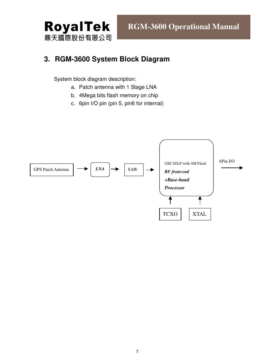
System block diagram description:
a. Patch antenna with 1 Stage LNA
b. 4Mega bits flash memory on chip
c. 6pin I/O pin (pin 5, pin6 for internal)
GPS Patch Antenna
LNA
SAW
SIRF
GSC3f/LP with 4M Flash
6Pin I/O
RF front-end
+Base-band
Processor
TCXO
XTAL
5
�
RGM-3600 Operational Manual
4. RGM-3600LP Technique Specification
No
Function
Specification
GPS receiver
1 Chipset
2 Frequency
3 Code
4 Channels
SiRF GSC3f/LP
L1 1575.42MHz.
C.A. Code.
20.
5 Chipset Sensitivity
-159dBm
6 Chipset cold start
35 sec @ open sky
7 Chipset warm start
35 sec @ open sky
8 Chipset hot start
1 sec @ open sky
9 Reacquisition
0.1sec typical
10 Position accuracy
10meters at 2D RMS.
11 Maximum altitude
18000 m
12 Maximum velocity
13 Trickle power mode
514 m/s
Duty cycle ≦ 34%. (Variable)
14 Update rate
17 Testability
Continuous operation: 1Hz
It shall be able to be tested by SiRF test mode IV
and single channel simulator.
18 Protocol setup
It shall store the protocol setup in the SRAM
Interface Description
19
I/O Pin
6 Pin
memory.
Mechanical requirements
20 Dimension
21 Weight
Power consumption
22 Vcc
23 Current
Pin1:RX Pin2:TX Pin3:GND Pin4:VCC
Pin5:NC Pin6: BOOT
(L)48.4 mm * (W)48.4 mm * (H)15.1mm ±3mm
≦30g
DC 5V ±5%
TTL Version
Acquisition: 55mA (typical) Tracking: 50mA (typical)
RS-232 Version
Acquisition: 60mA (typical) Tracking: 55 mA (typical)
6
�
RGM-3600 Operational Manual
24 SRAM backup battery
3.3mAhr Li-Ion rechargeable battery. Battery life at
full charge is ≥ 7 days.
Environment
25 Operating temperature
-20 ~ +60℃
26 Storage temperature
-20 ~ +60℃
27 Humidity
≦95%
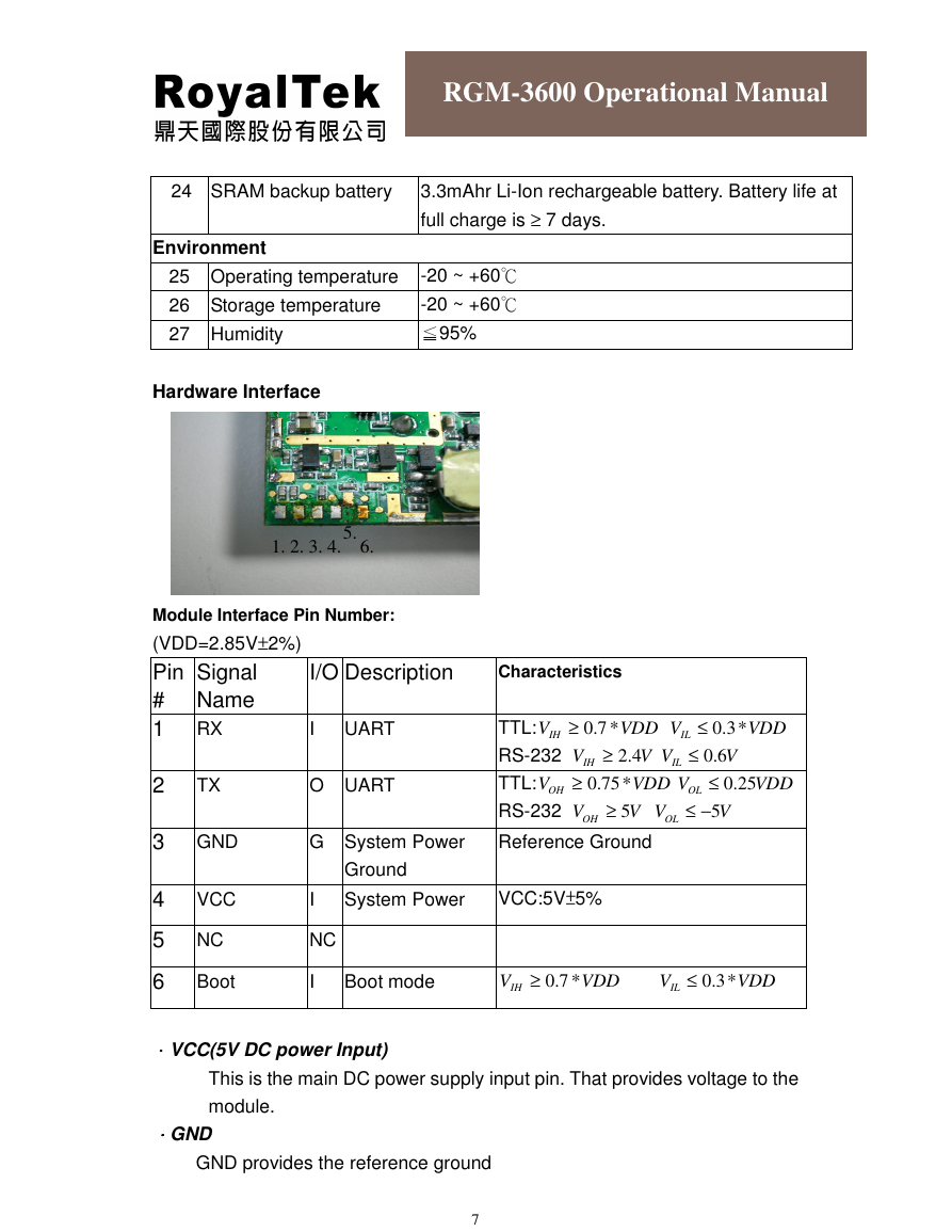
Hardware Interface
5.
1. 2. 3. 4. 6.
Module Interface Pin Number:
(VDD=2.85V±2%)
Pin
#
1 RX
Signal
Name
I/O Description
Characteristics
I UART
TTL:
V
IH
≥
*7.0
VDD
V
IL
≤
*3.0
VDD
RS-232
V
IH
≥
4.2
VV
IL
≤
6.0
V
2
TX
O UART
TTL:
V
OH
≥
*75.0
VDD
V
OL
≤
25.0
VDD
RS-232
V
OH
≥
5
VV
OL
3 GND
G System Power
Reference Ground
Ground
4
VCC
I System Power
VCC:5V±5%
5 NC
NC
Boot
I Boot mode
V
IH
≥
*7.0
6
VDD
V
IL
−≤
5
V
≤
*3.0
VDD
....VCC(5V DC power Input)
This is the main DC power supply input pin. That provides voltage to the
module.
....GND
GND provides the reference ground
7
�
RGM-3600 Operational Manual
....RXA
This is the main receiver channel and is used for receiving software
commands to the board from SiRFdemo software or software written by
users themselves.
PS: Pull up if not used.
....TXA
This is the main transmitting channel and is used for outputting navigation and
measurement data for SiRFdemo software or software written by users
themselves.
....Boot
Set this pin to high for programming flash.
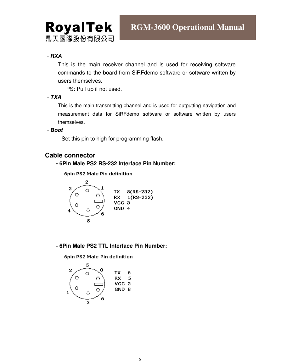
Cable connector
- 6Pin Male PS2 RS-232 Interface Pin Number:
- 6Pin Male PS2 TTL Interface Pin Number:
8
�




 2023年江西萍乡中考道德与法治真题及答案.doc
 2012年重庆南川中考生物真题及答案.doc
 2013年江西师范大学地理学综合及文艺理论基础考研真题.doc
 2020年四川甘孜小升初语文真题及答案I卷.doc
 2020年注册岩土工程师专业基础考试真题及答案.doc
 2023-2024学年福建省厦门市九年级上学期数学月考试题及答案.doc
 2021-2022学年辽宁省沈阳市大东区九年级上学期语文期末试题及答案.doc
 2022-2023学年北京东城区初三第一学期物理期末试卷及答案.doc
 2018上半年江西教师资格初中地理学科知识与教学能力真题及答案.doc
 2012年河北国家公务员申论考试真题及答案-省级.doc
 2020-2021学年江苏省扬州市江都区邵樊片九年级上学期数学第一次质量检测试题及答案.doc
 2022下半年黑龙江教师资格证中学综合素质真题及答案.doc