SSttaarrUUttiill
UUsseerr GGuuiiddee
NavCom Technology, Inc.
20780 Madrona Avenue
Torrance, CA 90503
USA
Tel: +1 310.381.2000
Fax: +1 310.381.2001
sales@navcomtech.com
www.navcomtech.com
�
�
STARUTIL User Guide Rev. E
Chapter 1
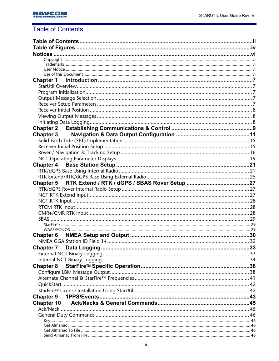
Table of Contents
Table of Contents.................................................................................................................ii
Table of Figures ..................................................................................................................iv
Notices .................................................................................................................................vi
Copyright................................................................................................................................................................. vi
Trademarks .............................................................................................................................................................. vi
User Notice .............................................................................................................................................................. vi
Use of this Document ............................................................................................................................................... vi
Introduction.....................................................................................................7
StarUtil Overview......................................................................................................................... 7
Program Initialization................................................................................................................... 7
Output Message Selection ........................................................................................................... 7
Receiver Setup Parameters........................................................................................................... 7
Receiver Initial Position ................................................................................................................ 8
Viewing Output Messages ........................................................................................................... 8
Initiating Data Logging................................................................................................................ 8
Chapter 2 Establishing Communications & Control .....................................................9
Navigation & Data Output Configuration ................................................11
Chapter 3
Solid Earth Tide (SET) Implementation....................................................................................... 15
Receiver Initial Position Setup .................................................................................................... 15
Rover / Navigation & Tracking Setup......................................................................................... 16
NCT Operating Parameter Displays............................................................................................ 19
Chapter 4 Base Station Setup .......................................................................................21
RTK/dGPS Base Using Internal Radio .......................................................................................... 21
RTK Extend/RTK/dGPS Base Using External Radio....................................................................... 25
Chapter 5 RTK Extend / RTK / dGPS / SBAS Rover Setup .........................................27
RTK/dGPS Rover Internal Radio Setup ........................................................................................ 27
NCT RTK Extend Input............................................................................................................... 27
NCT RTK Input .......................................................................................................................... 28
RTCM RTK Input........................................................................................................................ 28
CMR+/CMR RTK Input............................................................................................................... 28
SBAS ......................................................................................................................................... 29
StarFire™ ................................................................................................................................................................. 29
WAAS/EGNOS ......................................................................................................................................................... 29
Chapter 6 NMEA Setup and Output ..............................................................................30
NMEA GGA Station ID Field 14.................................................................................................. 32
Chapter 7 Data Logging.................................................................................................33
External NCT Binary Logging..................................................................................................... 33
Internal NCT Binary Logging ..................................................................................................... 34
Chapter 8 StarFire™ Specific Operation.......................................................................38
Configure LBM Message Output................................................................................................ 38
Alternate Channel & StarFire™ Frequencies ............................................................................... 41
QuickStart ................................................................................................................................. 42
StarFire™ License Installation Using StarUtil................................................................................ 42
Chapter 9 1PPS/Events..................................................................................................43
Chapter 10 Ack/Nacks & General Commands............................................................45
Ack/Nack................................................................................................................................... 45
General Duty Commands .......................................................................................................... 46
Key.......................................................................................................................................................................... 46
Get Almanac ........................................................................................................................................................... 46
Get Almanac To File ................................................................................................................................................ 46
Send Almanac From File .......................................................................................................................................... 46
ii
�
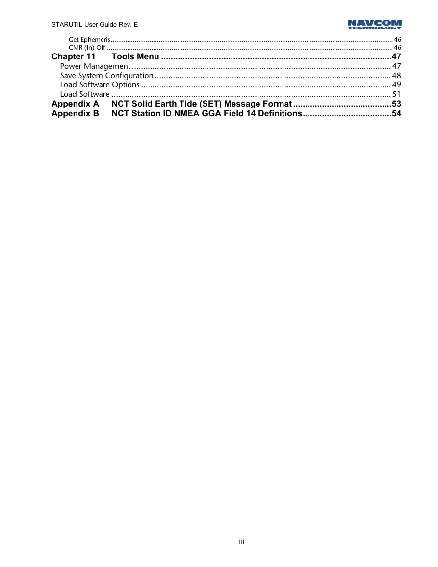
Chapter 11
STARUTIL User Guide Rev. E
Get Ephemeris......................................................................................................................................................... 46
CMR (In) Off ........................................................................................................................................................... 46
Tools Menu ................................................................................................47
Power Management .................................................................................................................. 47
Save System Configuration ........................................................................................................ 48
Load Software Options .............................................................................................................. 49
Load Software ........................................................................................................................... 51
Appendix A NCT Solid Earth Tide (SET) Message Format .........................................53
Appendix B NCT Station ID NMEA GGA Field 14 Definitions.....................................54
iii
�
STARUTIL User Guide Rev. E
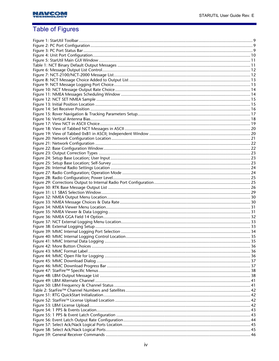
Table of Figures
Figure 1: StarUtil Toolbar.................................................................................................................................................... 9
Figure 2: PC Port Configuration .......................................................................................................................................... 9
Figure 3: PC Port Status Bar ................................................................................................................................................ 9
Figure 4: Unit Port Configuration...................................................................................................................................... 10
Figure 5: StarUtil Main GUI Window ................................................................................................................................. 11
Table 1: NCT Binary Default Output Messages ................................................................................................................. 11
Figure 6: Message Output List Control.............................................................................................................................. 12
Figure 7: NCT-2100/NCT-2000 Message List.................................................................................................................... 12
Figure 8: NCT Message Choice Added to Output List ....................................................................................................... 13
Figure 9: NCT Message Logging Port Choice.................................................................................................................... 13
Figure 10: NCT Message Output Rate Choice ................................................................................................................... 14
Figure 11: NMEA Messages Scheduling Window .............................................................................................................. 14
Figure 12: NCT SET NMEA Sample ................................................................................................................................... 15
Figure 13: Initial Position Location .................................................................................................................................... 15
Figure 14: Set Receiver Position ........................................................................................................................................ 16
Figure 15: Rover Navigation & Tracking Parameters Setup................................................................................................ 17
Figure 16: Vertical Antenna Bias........................................................................................................................................ 18
Figure 17: View NCT in ASCII Choice................................................................................................................................ 19
Figure 18: View of Tabbed NCT Messages in ASCII ........................................................................................................... 20
Figure 19: View of Tabbed 0xB1 in ASCII; Independent Window ...................................................................................... 20
Figure 20: Network Configuration Location ...................................................................................................................... 21
Figure 21: Network Configuration .................................................................................................................................... 22
Figure 22: Base Configuration Window............................................................................................................................. 22
Figure 23: Output Correction Types ................................................................................................................................. 23
Figure 24: Setup Base Location; User Input ....................................................................................................................... 23
Figure 25: Setup Base Location; Self-Survey ...................................................................................................................... 23
Figure 26: Internal Radio Settings Location ....................................................................................................................... 24
Figure 27: Radio Configuration; Operation Mode ............................................................................................................. 24
Figure 28: Radio Configuration; Power Level..................................................................................................................... 25
Figure 29: Corrections Output to Internal Radio Port Configuration.................................................................................. 25
Figure 30: RTK Base Message Output List ......................................................................................................................... 26
Figure 31: L1 SBAS Selection Window............................................................................................................................... 29
Figure 32: NMEA Output Menu Location.......................................................................................................................... 30
Figure 33: NMEA Message Choices & Data Rate ............................................................................................................... 30
Figure 34: NMEA Viewer Menu Location........................................................................................................................... 31
Figure 35: NMEA Viewer & Data Logging......................................................................................................................... 31
Figure 36: NMEA GGA Field 14 Option............................................................................................................................. 32
Figure 37: NCT External Logging Menu Location.............................................................................................................. 33
Figure 38: External Logging Setup .................................................................................................................................... 33
Figure 39: MMC Internal Logging Port Selection .............................................................................................................. 34
Figure 40: MMC Internal Logging Control Location.......................................................................................................... 35
Figure 41: MMC Internal Data Logging ............................................................................................................................ 35
Figure 42: More Button Choices ....................................................................................................................................... 36
Figure 43: MMC Format Label .......................................................................................................................................... 36
Figure 44: MMC Open File for Logging ............................................................................................................................ 36
Figure 45: MMC Download Dialog ................................................................................................................................... 37
Figure 46: MMC Download Progress Bar .......................................................................................................................... 37
Figure 47: StarFire™ Specific Menus ................................................................................................................................. 38
Figure 48: LBM Output Message List ................................................................................................................................ 38
Figure 49: LBM Alternate Channel .................................................................................................................................... 41
Figure 50: LBM Frequency & Channel Status .................................................................................................................... 41
Table 2: StarFire™ Channel Numbers and Satellites .......................................................................................................... 42
Figure 51: RTG QuickStart Initialization............................................................................................................................. 42
Figure 52: StarFire™ License Upload Location ................................................................................................................... 42
Figure 53: LBM License Upload......................................................................................................................................... 42
Figure 54: 1 PPS & Events Location................................................................................................................................... 43
Figure 55: 1 PPS & Event Latch Configuration .................................................................................................................. 43
Figure 56: Event Latch Output Rate Configuration............................................................................................................ 44
Figure 57: Select Ack/Nack Logical Ports Location............................................................................................................. 45
Figure 58: Select Ack/Nack Logical Ports........................................................................................................................... 45
Figure 59: General Receiver Commands ........................................................................................................................... 46
iv
�
STARUTIL User Guide Rev. E
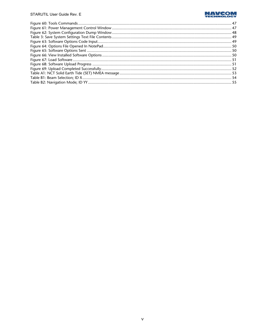
Figure 60: Tools Commands ............................................................................................................................................. 47
Figure 61: Power Management Control Window .............................................................................................................. 47
Figure 62: System Configuration Dump Window.............................................................................................................. 48
Table 3: Save System Settings Text File Contents .............................................................................................................. 49
Figure 63: Software Options Code Input........................................................................................................................... 49
Figure 64: Options File Opened In NotePad...................................................................................................................... 50
Figure 65: Software Options Sent ..................................................................................................................................... 50
Figure 66: View Installed Software Options ....................................................................................................................... 50
Figure 67: Load Software .................................................................................................................................................. 51
Figure 68: Software Upload Progress ................................................................................................................................ 51
Figure 69: Upload Completed Successfully........................................................................................................................ 52
Table A1: NCT Solid Earth Tide (SET) NMEA message ....................................................................................................... 53
Table B1: Beam Selection; ID X......................................................................................................................................... 54
Table B2: Navigation Mode; ID YY.................................................................................................................................... 55
v
�
Notices
STARUTIL User Guide Rev. E
StarUtil Engineering Program User Guide
P/N 96-310008-3001
Revision E
July 2005
Copyright
© 2003 by NavCom Technology, Inc.
All rights reserved. No part of this work or the computer programs described herein may be
reproduced or stored or transmitted by any means, without the written permission of the copyright
holders. Translation in any language is prohibited without the permission of the copyright holders.
Trademarks
The ‘find your way’, ‘NavCom Globe’ and NAVCOM TECHNOLOGY logos are trademarks of
NavCom Technology, Inc. StarFire™ is a registered trademark of Deere & Company. All other
product and brand names are trademarks or registered trademarks of their respective holders.
User Notice
NAVCOM TECHNOLOGY, INC. SHALL NOT BE RESPONSIBLE FOR ANY INACCURACIES, ERRORS, OR
OMISSIONS IN INFORMATION CONTAINED HEREIN, INCLUDING, BUT NOT LIMITED TO,
INFORMATION OBTAINED FROM THIRD PARTY SOURCES, SUCH AS PUBLICATIONS OF OTHER
COMPANIES, THE PRESS, OR COMPETITIVE DATA ORGANIZATIONS.
THIS PUBLICATION IS MADE AVAILABLE ON AN “AS IS” BASIS AND NAVCOM TECHNOLOGY, INC.
SPECIFICALLY DISCLAIMS ALL ASSOCIATED WARRANTIES, WHETHER EXPRESS OR IMPLIED. IN NO
EVENT WILL NAVCOM TECHNOLOGY, INC. BE LIABLE FOR DIRECT, INDIRECT, SPECIAL,
INCIDENTAL, OR CONSEQUENTIAL DAMAGES IN CONNECTION WITH THE USE OF OR RELIANCE
ON THE MATERIAL CONTAINED IN THIS PUBLICATION, EVEN IF ADVISED OF THE POSSIBILITY OF
SUCH DAMAGES. NAVCOM TECHNOLOGY, INC. RESERVES THE RIGHT TO MAKE IMPROVEMENTS
OR CHANGES TO THIS PUBLICATION AND THE PRODUCTS AND SERVICES HEREIN DESCRIBED AT
ANY TIME, WITHOUT NOTICE OR OBLIGATION.
Use of this Document
This User Guide is intended to be used by someone familiar with the concepts of GPS and satellite
surveying equipment.
Note indicates additional information to make better use of the product.
Indicates a caution, care, and/or safety situation.
vi
�
STARUTIL User Guide Rev. E
Chapter 1
StarUtil Overview
Introduction
StarUtil is designed for use as an Engineering/OEM application. This utility is primarily used to assist
in the development of user controller solutions. It is a powerful utility that allows the user to view,
and or configure any of the NavCom Technology, Inc. GPS receivers to any Base or Rover
configuration. It also affords the user the luxury of viewing receiver operations such as Channel
Status, Position Information, Raw Measurements, and many other engineering level receiver
operations, which are not necessarily useful to a user.
StarUtil allows the user to log output data to a file on the computer’s hard drive or to the internal
Memory Module Card (MMC). This data can then be used for post processing or data analysis.
All examples and references in this User Guide are relative to the factory default setup, which is
Rover configuration. In the examples and references to Base setup, NavCom Technology, Inc.
proprietary binary RTK Base configuration is assumed.
Program Initialization
After clicking on the StarUtil Icon, the utility automatically reads the available serial ports (i.e. RS-232
ports) from the Windows® OS registry. You are then given the option to manually choose a baud
rate for the PC port you have chosen, or you may have the program automatically detect the baud
rate for you.
Output Message Selection
The NCT-2100/NCT-2000 GPS Engine receiver comes with a default list of messages enabled. In
the case of the NCT binary messages, you will see these messages scrolling upward on the Messages
screen of StarUtil. The Technical Reference Manual (TRM) provides a detailed accounting of all NCT
binary messages that can be output from the receiver, any of which can be included or excluded in
the NCT-2100/NCT-2000 Messages window. The user has the ability to choose the rate at which
the messages are output from the receiver at any of 6-present rates, or by manually entering a value.
The user has the additional option of choosing a message to be output “on change” indicating that
the receiver will not output a particular message until a minimum of 1 bit has changed in the
message. NMEA output messages can be viewed, and logged in their own display screen, while the
output rate is chosen in a similar fashion as the NCT binary.
The NMEA messages GGA, RMC, and VTG follow the outpu rate of the 0xB1 message up to a
rate of 10 HZ, when NMEA output rate for thee messages are set to “On Change”. Setting the
oxB1 message rate greater than 10 HZ will force the GGA, RMC, and VTG messages to a 1 Hz
output rate.
s
t
Receiver Setup Parameters
StarUtil has been designed to allow the user the flexibility of configuring the receiver as a Base or
Rover receiver. Tool bar icons are provided to simplify the process of configuring the receiver for
typical Base or Rover operation (i.e. single button setup). If the user has more specific requirements,
1 - 7
�




 2023年江西萍乡中考道德与法治真题及答案.doc
 2012年重庆南川中考生物真题及答案.doc
 2013年江西师范大学地理学综合及文艺理论基础考研真题.doc
 2020年四川甘孜小升初语文真题及答案I卷.doc
 2020年注册岩土工程师专业基础考试真题及答案.doc
 2023-2024学年福建省厦门市九年级上学期数学月考试题及答案.doc
 2021-2022学年辽宁省沈阳市大东区九年级上学期语文期末试题及答案.doc
 2022-2023学年北京东城区初三第一学期物理期末试卷及答案.doc
 2018上半年江西教师资格初中地理学科知识与教学能力真题及答案.doc
 2012年河北国家公务员申论考试真题及答案-省级.doc
 2020-2021学年江苏省扬州市江都区邵樊片九年级上学期数学第一次质量检测试题及答案.doc
 2022下半年黑龙江教师资格证中学综合素质真题及答案.doc