Anchor Manual 2010
The Guide to Anchoring
�
2
anchor manual 2010
Vryh of Anchors BV
P.O. Box 109, 2900 AC Capelle a/d Yssel, The Neth er lands
www.vryhof.com vryhof@vryhof.com
Copyright
© Vryhof Anchors B.V., Capelle a/d Yssel, The Netherlands 2010.
No part of this book may be reproduced in any form, by print, copy or in any other way without
written permission of vryhof.
Vryhof, Stevin, Stevpris, Stevshark, Stevtensioner and Stevmanta are registered trade marks.
Vryhof reserves all intellectual and industrial property rights such as any and all of their patent,
trademark, design, manufacturing, reproduction, use and sales rights thereto and to any article
disclosed therein.
All information in this manual is subject to change without prior notice. Vryhof Anchors is not
liable and/or responsible in any way for the information provided in this manual.
First edition published 1984. Print run 7,500 copies.
Second edition published 1990. Print run 7,500 copies.
Reprint second edition. Print run 5,000 copies.
Third edition published 2000. Print run 2,500 copies.
Reprint third edition print run 1,500 copies.
Second reprint third edition print run 1,000 copies.
First print fourth edition published 2006 print run 1,000 copies.
Second print fourth edition print run 1,000 copies.
Third print fourth edition print run 1,000 copies.
Fourth print fourth edition print run 1,000 copies.
�
Company profile
Since the beginning of exploration of oil & gas offshore the art of anchoring
has taken a dramatic turn. Vryhof Anchors was one of the pioneers and
achieved holding powers up to 25 times an anchor's own weight.
Consequently the company soon emerged as market leader in anchor
design and manufacturing and with over 7500 units sold, its anchors are
the most applied offshore.
Vryhof understood that clients’ needs cannot be satisfied by supply of
standard hardware alone. With best-in-class sales services it shared technology
to create fit-for-purpose mooring systems; it initiated lease/purchase
concepts and introduced an alliance of leading mooring component manu-
facturers in order to more efficiently serve a changing offshore industry in
the 1990s.
Exploration in ever deeper waters and more remote locations has encour-
aged the development of more advanced mooring solutions. Consequently
Vryhof anchor holding powers now reach beyond 75x their weight. Once
again, the industry welcomes new ways of cooperation to include supply of
complete mooring systems and lease concepts.
This sets the stage for Vryhof, who under new private ownership and with
a presence in major offshore arena’s will continue to responsibly introduce
quality designs in pace with industry's requirements; to explore opportunities
to approach clients in an open, sincere, professional manner and take its
world class services well into a new era for the benefit and satisfaction of its
clients.
�
Introduction
4
A stone and something that looked like a rope. For millennia this was the
typical anchor. Over the last 25 years of more recent history, vryhof has
brought the art to a more mature status. They have grown into a world
leader in engineering and manufacturing of mooring systems for all kinds
of floating structures. In doing so the company has secured numerous
anchor and ancillary equipment patents, and shared its experience with others.
The company understands that the needs of the industry can not be satisfied
by the supply of standard hard-ware only. Universal and tailored solutions
rooted in proven engineering should be based on long practical experience.
Vryhof has been and will be introducing new and original anchor designs
well into the 21st century. With their products, advice and this manual, it
shares this knowledge with those who are daily faced with complex mooring
situations.
This manual is intended as a means of reference for all who purchase, use,
maintain, repair or are in any way involved with anchors. Though written
from one anchor manufacturer’s standpoint, the information contained
herein is applicable to many types of anchors. Total objectivity is, of course,
impossible.
It is hoped this manual will contribute to the work and success of all who
work with anchors. They are the only fixed reference point for many of the
floating structures on the world’s often turbulent waters.
�
1
General
�
Mooring systems
6
Mooring systems have been around just as long as man has felt the need for
anchoring a vessel at sea. These systems were used, and are still used, on
ships and consisted of one or more lines connected to the bow or stern of
the ship. Generally the ships stayed moored for a short duration of time
(days).
When the exploration and production of oil and gas started offshore, a
need for more permanent mooring systems became apparent. Numerous
different mooring systems have been developed over the years, of which a
short selection is presented here.
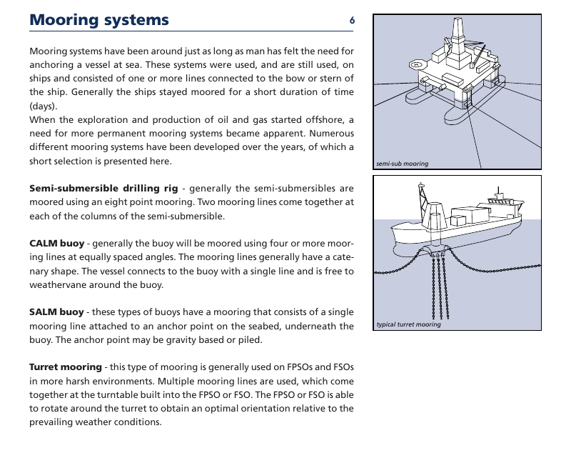
Semi-submersible drilling rig - generally the semi-submersibles are
moored using an eight point mooring. Two mooring lines come together at
each of the columns of the semi-submersible.
CALM buoy - generally the buoy will be moored using four or more moor-
ing lines at equally spaced angles. The mooring lines generally have a cate-
nary shape. The vessel connects to the buoy with a single line and is free to
weathervane around the buoy.
semi-sub mooring
SALM buoy - these types of buoys have a mooring that consists of a single
mooring line attached to an anchor point on the seabed, underneath the
buoy. The anchor point may be gravity based or piled.
typical turret mooring
Turret mooring - this type of mooring is generally used on FPSOs and FSOs
in more harsh environments. Multiple mooring lines are used, which come
together at the turntable built into the FPSO or FSO. The FPSO or FSO is able
to rotate around the turret to obtain an optimal orientation relative to the
prevailing weather conditions.
�
Mooring systems
7
catenary system
fig. 1-01
taut leg system
fig. 1-02
Spread mooring - generally used on FPSOs and FSOs in milder environ-
ments. The mooring lines are directly connected to the FPSO or FSO at both
the stern and bow of the vessel.
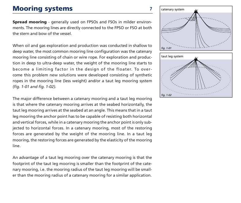
When oil and gas exploration and production was conducted in shallow to
deep water, the most common mooring line configuration was the catenary
mooring line consisting of chain or wire rope. For exploration and produc-
tion in deep to ultra-deep water, the weight of the mooring line starts to
become a limiting factor in the design of the floater. To over-
come this problem new solutions were developed consisting of synthetic
ropes in the mooring line (less weight) and/or a taut leg mooring system
(fig. 1-01 and fig. 1-02).
The major difference between a catenary mooring and a taut leg mooring
is that where the catenary mooring arrives at the seabed horizontally, the
taut leg mooring arrives at the seabed at an angle. This means that in a taut
leg mooring the anchor point has to be capable of resisting both horizontal
and vertical forces, while in a catenary mooring the anchor point is only sub-
jected to horizontal forces. In a catenary mooring, most of the restoring
forces are generated by the weight of the mooring line. In a taut leg
mooring, the restoring forces are generated by the elasticity of the mooring
line.
An advantage of a taut leg mooring over the catenary mooring is that the
footprint of the taut leg mooring is smaller than the footprint of the cate-
nary mooring, i.e. the mooring radius of the taut leg mooring will be small-
er than the mooring radius of a catenary mooring for a similar application.
�
fig. 1-03
fig. 1-04
Mooring components
8
A typical mooring system can be divided in three different components, the
mooring line, the connectors and the anchor point.
Mooring line
Chain
The most common product used for mooring lines is chain which is available
in different diameters and grades. Two different designs of chain are used
frequently, studlink and studless chain. The studlink chain is most common-
ly used for moorings that have to be reset numerous times during their life-
time, for instance semi-submersibles, while studless link chain is often used
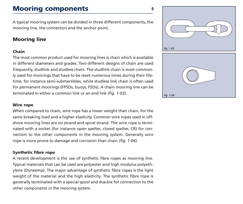
for permanent moorings (FPSOs, buoys, FSOs). A chain mooring line can be
terminated in either a common link or an end link (fig. 1-03).
Wire rope
When compared to chain, wire rope has a lower weight than chain, for the
same breaking load and a higher elasticity. Common wire ropes used in off-
shore mooring lines are six strand and spiral strand. The wire rope is termi-
nated with a socket (for instance open spelter, closed spelter, CR) for con-
nection to the other components in the mooring system. Generally wire
rope is more prone to damage and corrosion than chain (fig. 1-04).
Synthetic fibre rope
A recent development is the use of synthetic fibre ropes as mooring line.
Typical materials that can be used are polyester and high modulus polyeth-
ylene (Dyneema). The major advantage of synthetic fibre ropes is the light
weight of the material and the high elasticity. The synthetic fibre rope is
generally terminated with a special spool and shackle for connection to the
other components in the mooring system.
�



 2023年江西萍乡中考道德与法治真题及答案.doc
 2012年重庆南川中考生物真题及答案.doc
 2013年江西师范大学地理学综合及文艺理论基础考研真题.doc
 2020年四川甘孜小升初语文真题及答案I卷.doc
 2020年注册岩土工程师专业基础考试真题及答案.doc
 2023-2024学年福建省厦门市九年级上学期数学月考试题及答案.doc
 2021-2022学年辽宁省沈阳市大东区九年级上学期语文期末试题及答案.doc
 2022-2023学年北京东城区初三第一学期物理期末试卷及答案.doc
 2018上半年江西教师资格初中地理学科知识与教学能力真题及答案.doc
 2012年河北国家公务员申论考试真题及答案-省级.doc
 2020-2021学年江苏省扬州市江都区邵樊片九年级上学期数学第一次质量检测试题及答案.doc
 2022下半年黑龙江教师资格证中学综合素质真题及答案.doc