IEEE TRANSACTIONS ON ROBOTICS, VOL. 28, NO. 1, FEBRUARY 2012
61
Visual-Inertial-Aided Navigation for High-Dynamic
Motion in Built Environments Without
Initial Conditions
Todd Lupton and Salah Sukkarieh
Abstract—In this paper, we present a novel method to fuse ob-
servations from an inertial measurement unit (IMU) and visual
sensors, such that initial conditions of the inertial integration,
including gravity estimation, can be recovered quickly and in a
linear manner, thus removing any need for special initialization
procedures. The algorithm is implemented using a graphical simul-
taneous localization and mapping like approach that guarantees
constant time output. This paper discusses the technical aspects
of the work, including observability and the ability for the system
to estimate scale in real time. Results are presented of the system,
estimating the platforms position, velocity, and attitude, as well as
gravity vector and sensor alignment and calibration on-line in a
built environment. This paper discusses the system setup, describ-
ing the real-time integration of the IMU data with either stereo or
monocular vision data. We focus on human motion for the pur-
poses of emulating high-dynamic motion, as well as to provide a
localization system for future human–robot interaction.
Index Terms—Field robots,
robots, sensor fusion.
localization, search-and-rescue
I. INTRODUCTION
T HE motivation of this paper was inspired by the need to
develop a human-mounted localization system for first re-
sponse units, such as fire fighters, counter-terrorism groups, and
search-and-rescue operators. The system had to keep track of
the location of the operator in an unknown building in real
time. The system could not use any purpose built localiza-
tion infrastructure and had to provide information that could
be shared with the future incorporation of robotic systems in the
mission.
A human-mounted localization system for first responders
operating in built environments poses a number of difficulties.
There is the lack of (or poor) global positioning system (GPS)
signals, unreliable magnetic readings, high-dynamic motion,
Manuscript received September 7, 2010; revised April 28, 2011; accepted
September 21, 2011. Date of publication November 29, 2011; date of current
version February 9, 2012. This paper was recommended for publication by
Associate Editor J. Neira and Editor D. Fox upon evaluation of the reviewers’
comments. This work was supported in part by the Australian Research Council
(ARC) Centre of Excellence programme, funded by the ARC and the New South
Wales State Government, and by ARC Discovery under Grant DP0665439.
T. Lupton was with The University of Sydney, Sydney, N.S.W. 2006,
Australia. He is now with Silverbrook Research, Balmain, N.S.W. 2041,
Australia (e-mail: tlup8791@uni.sydney.edu.au).
S. Sukkarieh is with The University of Sydney, Sydney, N.S.W. 2006,
Australia (e-mail: salah@acfr.usyd.edu.au).
Color versions of one or more of the figures in this paper are available online
at http://ieeexplore.ieee.org.
Digital Object Identifier 10.1109/TRO.2011.2170332
and the lack of any internal localization infrastructure. A local-
ization system would, thus, need to use whatever features were
available in the environment, but the closeness of objects in the
buildings, as well as the presence of walls, means that landmark
features may only be observable for short periods of time. The
system must also be able to quickly initialize and handle periods
when few or no external landmarks are observed.
Cameras can work with landmarks of opportunity that al-
ready exist in the environment; therefore, no external infras-
tructure is required. Indoor Simultaneous Localization and Map-
ping (SLAM) using a single camera has been developed in the
past [4]; however, this implementation had to operate at a high
frame rate, i.e., up to 200 Hz [9], and even then, only slow dy-
namics and certain restricted motions could be used. In addition,
as a single camera only provides bearing observations, special-
ized landmark initialization techniques are required as range is
not immediately observable, and the scale of the environment
and, therefore, the motions cannot be determined.
The use of a stereo camera pair for SLAM [17], [18] or visual
odometry [11] gives very promising results for this kind of
application. In addition to providing more constrained motion
estimates, the true map scale can be observed and scale drift over
the trajectory is eliminated. The close proximity to landmarks
and visually rich environments contribute greatly to its success.
The main shortcoming of a system that relies solely on visual
observations is that it will fail when sufficient visual landmarks
are not observable, even if for just a short period of time. This
could easily be the case for human-mounted systems that are
considered in this paper. For example, loss of distinct visual
features can occur in dark areas of buildings, due to motion
blur, if smoke is present, or if the cameras are very close to
blank walls such as in narrow corridors or staircases.
The use of an inertial measurement unit (IMU) could help
in these momentary periods where visual observations may not
be available [19]. Even a low-cost IMU can observe the high
dynamics of such a system and can constrain the estimated lo-
cation for short periods once properly initialized. The difficulty
in using an IMU in these applications is one of obtaining proper
initialization.
In this paper, the development and analysis of a novel system
to process and fuse inertial observations with observations from
other body frame sensors, such as cameras, is presented. This
system is inspired by the idea that inertial observations can
be integrated in an arbitrary frame between poses to form a
single pseudo-observation, as presented in [16]. This core idea is
expanded in this paper with integration into a graphical filter that
1552-3098/$26.00 © 2011 IEEE
�
62
IEEE TRANSACTIONS ON ROBOTICS, VOL. 28, NO. 1, FEBRUARY 2012
allows automatic inertial initialization and map management to
produce a robust visual-inertial navigation system.
The main contribution of this paper is that no explicit ini-
tialization stage or large uncertainty priors are required, and the
initial conditions are automatically recovered in a linear manner.
This is achieved by performing the inertial observation mathe-
matical integration in a body fixed frame that moves with the
vehicle. Postintegration, both gravity and initial velocity are lin-
early corrected in the navigation frame, the orientation of which
is fixed to the initial vehicle orientation. This way, the grav-
ity vector is estimated directly instead of estimating initial roll
and pitch, thus removing the major source of nonlinearity from
inertial navigation.
As a consequence, the initial velocity and gravity vector in
this frame can be recovered quickly and linearly after the ob-
servations have been integrated. These developments lead to a
quickly initializing and accurate navigation solution that is toler-
ant to faults and can quickly recover from errors automatically.
Section II of this paper provides a background on inertial nav-
igation and SLAM techniques and discusses their relevance to
the considered application. Section III details the development
of the new inertial observation processing algorithm, which we
call inertial preintegration, while Section IV explains the cal-
culation of its covariance and Jacobian components that are
required for implementation.
In Section V, the concept of performing inertial navigation
in a body referenced navigation frame instead of the traditional
globally referenced frame is discussed. The reasons why this
approach works for the considered application are explained
as well as the advantages gained from it. Section VI gives
an overview of the proposed inertial navigation technique as
a whole discussing how all the components work together to
make the initial conditions linearly observable.
Section VII details the implementation of the developed
visual-inertial navigation system as a whole. While Section VIII
provides a number of experimental results analyzing the perfor-
mance of the system in real-world environments.
A conclusion is then provided in Section IX-A and future
work in Section IX-B.
II. AIDED INERTIAL NAVIGATION
A. Inertial Navigation
IMUs were primarily developed and used for navigation in
the aerospace community [21]. In these applications, a globally
referenced and fixed navigation frame is used with aiding obser-
vations, such as GPS and magnetometer observations, and the
navigation solution is computed in this frame.
Acceleration and rotation rate observations are taken from the
IMU and transformed into this navigation frame before being
integrated to provide an estimate of the current position, velocity,
and attitude of the platform. In order for these estimates to
be obtained, the initial position, velocity, and attitude of the
platform in the frame must first be determined. This is known
as the initial condition requirement.
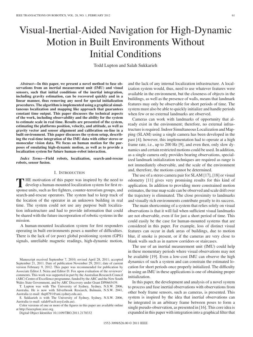
This process is illustrated in Fig. 1, where a number of poses of
interest are shown. The dotted line between the poses represents
Fig. 1.
Inertial navigation in a globally referenced navigation frame. Dotted
line represents the trajectory of the vehicle and the inertial observations taken
at these points. Inertial observations are transformed into the navigation frame
shown by the dashed lines.
the trajectory of the vehicle and the inertial observations taken at
these points. The inertial observations are then transformed into
the navigation frame shown by the dashed lines before being
integrated to obtain the navigation solution.
The initial attitude estimate is particularly important in order
to conduct gravity compensation because of its nonlinear effect
on the inertial observation integration. This implies that either
an initialization procedure or method of obtaining these initial
conditions is required.
These initial conditions can be obtained by an initialization
routine that places the vehicle at a known position, velocity,
and attitude to use as a starting point [3]. Other options also
include collecting IMU and aiding observations, such as GPS,
over a period of time and then performing a nonlinear batch
initialization to obtain the initial conditions or to just start with
a large uncertainty and try to converge to the true state of the
vehicle over time [13], [20].
B. Using Inertial Navigation in Simultaneous
Localization and Mapping
The algorithms for inertial navigation have been adapted for
use in SLAM applications [3], [8], [12], where observations
are made in a body referenced frame, such as with camera
observations.
These applications are usually only conducted over small
areas, where the curvature of the earth can be ignored and low-
cost IMUs are used such that earth rotation does not have a
significant effect. As a result, the inertial integration that is used
for navigation can be simplified; see (1)–(3), shown below, for
the position, velocity, and attitude estimates, respectively.
The C n
bt and En
bt terms are the rotation and rotation rate matri-
ces, respectively, from the current body frame to the navigation
frame using the current vehicle orientation φn
t
t2 = pn
pn
t1 + (t2 − t1)vn
t1 +
t2
t1
(C n
bt(f b
t
− biasobs
f
) + gn )dt2
(1)
�
LUPTON AND SUKKARIEH: VISUAL-INERTIAL-AIDED NAVIGATION FOR HIGH-DYNAMIC MOTION
63
DERIVATIVES OF THE INERTIAL PREDICTION EQUATIONS WITH RESPECT TO
ESTIMATED STATES
TABLE I
C. Inertial Simultaneous Localization and
Mapping Initialization
t1, and φn
t1 is provided at the beginning.
The navigation implementations that are discussed are com-
puted in a globally referenced frame. The inertial body frame
and visual observations are transformed into this frame before
being fused, and therefore, the initial condition requirement still
exists. This is shown in Algorithm 1, where the requirement for
t1, vn
pn
Table I shows the derivatives of the standard inertial integra-
tion equations [see (1)–(3)] with respect to the vehicle states. It
can be seen from this table that the majority of the nonlinearity
comes from the vehicle attitude terms (with some nonlinearity
with respect to the IMU bias terms as well). This is because of
the nonlinear sine and cosine terms in the rotation and rotation
rate matrices.
The position and velocity states have a perfectly linear in-
teraction and, therefore, do not pose a problem for a linear
estimator.
The major problem is with unknown initial attitude due to the
nonlinear effects it has on the estimate. This causes errors when
a linear estimator, such as an EKF, is used, and slow convergence
or even instability when a linearized batch solver is used.
In [3], the initial orientation and attitude of the unmanned
aerial vehicle was obtained by keeping it stationary on the run-
way, while GPS observations were made of its position, and
internal tilt sensors were used to get the roll and pitch. The use
of such an initialization routine is common, but for the situations
that are considered in this paper, it is inconvenient to the user.
In [13], the aircraft would fly with GPS and inertial obser-
vations being made over a period of time until sufficient in-
formation was available for the navigation solution to converge.
This large initial angle uncertainty technique, when applied with
an EKF or other nonrelinearizing implementation, suffers from
accumulated linearization errors from uncertainties in the ve-
hicle states. These are normally handled by adding additional
stabilizing noise to the filter by inflating the observation or pro-
cess model uncertainties. This procedure is often unstable for
high-dynamic applications, like the one considered in this paper,
where the initial attitude has a large range of possible values,
not just close to flat and level for aircraft applications.
As a result, a batch initialization routine is probably the best
suited to the target application as it does not require the user
to perform a specialized initialization routine, and it provides a
more numerically stable and accurate initialization.
III. INERTIAL PREINTEGRATION THEORY
Regardless of the initialization procedure chosen, all the IMU
observations are traditionally transformed into the navigation
t1
t2
t1
t2
(C n
bt(f b
t
En
bt(ωb
t
t2 = vn
vn
t1 +
t2 = φn
φn
t1 +
− biasobs
f
) + gn )dt
− biasobs
ω )dt.
(2)
(3)
As IMUs provide discrete time samples of the accelerations
and rotation rates experienced, these equations are used in their
discrete form. Algorithm 1 shows an example implementation
if used for state prediction in an extended Kalman filter (EKF).
For SLAM applications, both the integrated inertial naviga-
tion solution and the estimate of the uncertainty of that solution
are required. The uncertainty is needed so that when observa-
tions from other sensors are combined with the inertial observa-
tions, they can be weighted to give the optimal estimate of the
vehicle states.
Algorithm 2 shows how the uncertainty of the inertial nav-
igation solution, i.e., Pt2, can be calculated given the initial
vehicle state uncertainty Pt1, and the IMU sensor observation
noise covariance matrix Q.
�
64
IEEE TRANSACTIONS ON ROBOTICS, VOL. 28, NO. 1, FEBRUARY 2012
The initial conditions for the rotation matrix C bt1
of the integration period time t1 is C bt1
matrix.
bt at the start
bt1 , which is the Identity
These equations still provide the vehicle pose estimates in the
globally referenced navigation frame, but the integration of the
inertial observations between poses is performed in the body
frame of the last pose and then transformed into the navigation
frame after integration instead of before.
One thing to note from (4)–(6) is that the integrations are
performed in the vehicle body frame; the vehicle states with
respect to this frame can be perfectly known. As a result, the
inertial observations can actually be integrated with no initial
condition requirements, and even before the states themselves
are estimated.
If the integrals of the inertial observations from (4)–(6) are
extracted, the following equations are obtained:
t2
t1
t1
t2
t2
t1
f b
t
C bt1
bt
f b
t
ωb
t
Ebt1
bt
C bt1
bt
f
− biasobs
− biasobs
− biasobs
f
ω
dt2
dt
dt.
Δp+t1
t2 =
Δvt1
t2 =
Δφt1
t2 =
(7)
(8)
(9)
These terms that can be preintegrated without initial condi-
tions represent the change in position, velocity, and attitude of
the vehicle from pose 1 to pose 2 in the (moving) body frame
of pose 1.
These preintegrated sets of observations can then be used
as a single delta state observation in place of all the IMU ob-
servations that occur between these two poses. Therefore these
integrated terms will be referred to as preintegrated inertial delta
observations.
Once calculated these delta components can then be substi-
tuted back into (4)–(6) as in (10)–(12), shown below. In these
equations the integration of the gravity term has also been sim-
plified, which can be done as the gravity vector integrand con-
tains no time-dependent terms (the 1
2 factor in (10) is a byproduct
of the double integration process)
t2 = pn
pn
t1 + (t2 − t1)vn
t1 +
(t2 − t1)2gn + C n
bt1Δp+t1
t2
1
2
t2 = vn
vn
t2 = EulerF romDCM
φn
t1 + (t2 − t1)gn + C n
bt1Δvt1
t2
bt1ΔC bt1
C n
bt2
.
(10)
(11)
(12)
The delta attitude component ΔC bt1
bt2 is multiplied by the
previous attitude rotation matrix and then converted back into
the Euler representation that is used for state estimation. This
is done to avoid the small-angle approximation that is used by
the Euler rotation rate matrix as this may no longer be valid
for the longer integration integrals used. Furthermore, the delta
attitude component refers to an actual change in attitude over
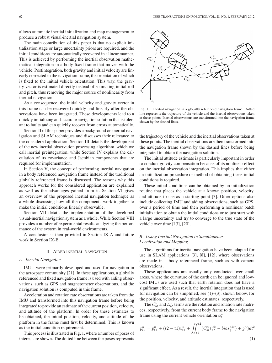
Fig. 2.
Inertial integration in the body frame of the last pose of interest.
frame before integration. IMUs are sampled at very high rates
when compared with other sensors that are used in navigation,
on the order of hundreds of samples per second, even in low-cost
units.
This requires updates to be performed at high rates for a
marginalizing filter, such as the EKF, or a large number of pose
states being required for delayed state methods. Another prob-
lem this causes, specifically for batch initialized inertial meth-
ods, is that it requires a large number of inertial observations
that are to be stored and processed in the batch filter once the
initial conditions become observable.
If these observations could be integrated first without knowing
the initial conditions of the vehicle, then a number of inertial
observations could be treated as a single observation in the filter,
reducing the problems that are listed previously.
One possible way to do this is to integrate the inertial observa-
tions between required poses in the body frame of the previous
pose, as presented in [16]. An illustration of this concept is
shown in Fig. 2, where the frame that is used for integration
of the inertial observations moves along with the vehicle from
pose to pose.
Since in many navigation applications, poses are only re-
quired at the rate of the next fastest sensor other than the IMU,
for example, the frame rate of the camera, and this sensor usually
takes samples at a much lower rate, many inertial observations
can be integrated between poses this way.
If the inertial integration equations (1)–(3) are rewritten to
perform the integration in the body frame of the last pose, the
following equations are obtained:
t2 = pn
pn
t1 + (t2 − t1)vn
+ C n
bt1
t2 = vn
vn
t1 +
t2 = φn
φn
t1 + En
bt1
t2
t2
t1
t1
t1 +
C bt1
bt
f b
t
gn dt + C n
bt1
t2
Ebt1
bt
t1
t2
t1
gn dt2
− biasobs
f
t2
C bt1
bt
t1
dt2
f b
t
ωb
t
dt.
− biasobs
ω
− biasobs
f
(4)
dt
(5)
(6)
�
LUPTON AND SUKKARIEH: VISUAL-INERTIAL-AIDED NAVIGATION FOR HIGH-DYNAMIC MOTION
65
the integration interval and not a rotation rate, as is the case with
the raw gyro observations.
A. Δp+ Component
The delta attitude ΔC bt1
bt2 and delta velocity Δvt1
t2 components
represent a change in the estimated states directly; however, an
observation of the change in position cannot be obtained from
the inertial observations alone. As the accelerometer observation
only provides acceleration measurements, the initial velocity of
the vehicle at the start of the integration interval is required.
As the integrations are performed without any knowledge of
the initial vehicle states, an integration reference frame located
at, and moving with, the previous body pose was used. Since the
reference frame is moving at the same instantaneous velocity
as the vehicle was at the previous pose, an initial velocity with
respect to this frame of zero can be used in the preintegrated
position delta (7), making integration without initial conditions
possible.
This, however, means that when the preintegrated inertial
delta observations are transformed back into the navigation
frame to predict the current vehicle pose, not only is a transla-
tion and rotation required, but the difference in reference frame
velocities needs to be accounted for as well.
Given the velocity estimate at the start of the integration
period, a simple constant velocity estimate of the new position
can be calculated. This new position estimate then forms the
reference frame transformation.
This form of constant velocity model is common in SLAM
when no other information is available; however the final posi-
tion of the platform will be dependent on the acceleration profile
over the integration period as well.
To take this acceleration profile into account, the Δp+ com-
ponent is used. It can be seen as a corrective term that is added
to the constant velocity prediction of the new vehicle position
to account for acceleration. The “+” superscript is used to dis-
tinguish it from a true delta position term and to indicate that it
is an additive correction.
the (t2 − t1)vn
bt1Δp+t1
C n
t2
In (10), the constant velocity prediction can be seen in
t1 component with the Δp+ correction in the
component.
B. Bias Correction
From the delta component in (7)–(9), it can be seen that the
initial velocity and attitude estimates are no longer required to
perform inertial observation integration. However the corrective
terms for the IMU sensor biases are still present.
If an estimate of the biases is present at the time of integration,
then they can be used in these calculations. However, if they are
not available or if they are inaccurate and are refined at a later
time, it would be useful to be able to correct for these biases
without having to reperform the integrations.
This is possible if the derivatives of the preintegrated inertial
delta observation components that are shown in (7)–(9) with
respect to the IMU biases are calculated. This will be shown in
Section IV-D.
IV. IMPLEMENTATION OF PREINTEGRATED INERTIAL DELTA
COMPONENT CALCULATIONS
The inertial preintegration technique that is described in
Section III generates a three-component pseudo-observation
from a number of raw IMU observations. These pseudo-
observations are referred to as preintegrated inertial delta
observations.
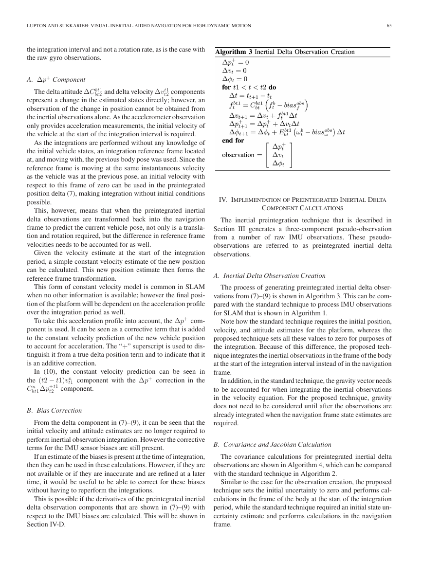
A. Inertial Delta Observation Creation
The process of generating preintegrated inertial delta obser-
vations from (7)–(9) is shown in Algorithm 3. This can be com-
pared with the standard technique to process IMU observations
for SLAM that is shown in Algorithm 1.
Note how the standard technique requires the initial position,
velocity, and attitude estimates for the platform, whereas the
proposed technique sets all these values to zero for purposes of
the integration. Because of this difference, the proposed tech-
nique integrates the inertial observations in the frame of the body
at the start of the integration interval instead of in the navigation
frame.
In addition, in the standard technique, the gravity vector needs
to be accounted for when integrating the inertial observations
in the velocity equation. For the proposed technique, gravity
does not need to be considered until after the observations are
already integrated when the navigation frame state estimates are
required.
B. Covariance and Jacobian Calculation
The covariance calculations for preintegrated inertial delta
observations are shown in Algorithm 4, which can be compared
with the standard technique in Algorithm 2.
Similar to the case for the observation creation, the proposed
technique sets the initial uncertainty to zero and performs cal-
culations in the frame of the body at the start of the integration
period, while the standard technique required an initial state un-
certainty estimate and performs calculations in the navigation
frame.
�
66
IEEE TRANSACTIONS ON ROBOTICS, VOL. 28, NO. 1, FEBRUARY 2012
E (Δvt|ˆxt) = C bt1
n
+ dΔvt
dbiasf
+ dΔvt
dbiasω
f
(vt2 − vt1 − ˆgΔt)
biasf − biasobs
biasω − biasobs
biasω − biasobs
ω
ω
+ dΔφt
dbiasω
E (Δφt|ˆxt) = EulerF romRotationM atrix(C bt1
n
(14)
C n
bt2)
(15)
where E(.) is the expected value operator, and ˆxt is the current
estimate of the mean of the vehicle states.
D. Postintegration Bias Correction
The dΔ .
dbias terms in (13)–(15) are the derivatives of the inertial
delta observation components with respect to the IMU biases.
They are used to correct for any changes in the estimated IMU
biases, since the preintegrated inertial delta observations were
formed.
The bias terms are the current estimates of the IMU biases,
and the biasobs terms are the bias values that are used to create
the preintegrated inertial delta observations.
The derivatives of the inertial delta observation components
with respect to the IMU bias terms are contained within the
preintegrated inertial delta observations Jacobian matrix J that
was calculated in Algorithm 4. The components of this matrix
can be seen in
⎡
⎢⎢⎢⎢⎢⎢⎢⎢⎢⎢⎢⎢⎢⎢⎢⎢⎢⎢⎣
dΔp+
t2
dpt1
t1
03
03
03
03
dΔp+
t2
dvt1
t1
dΔvt2
dvt1
t1
03
03
03
dΔp+
t2
dφt1
t1
dΔvt2
dφt1
t1
dΔφt2
dφt1
t1
03
03
dΔp+
t2
dbiasf
dΔvt2
dbiasf
03
dbiasf
dbiasf
03
dΔp+
t2
dbiasω
dΔvt2
dbiasω
dΔφt2
dbiasω
03
dbiasω
dbiasω
⎤
⎥⎥⎥⎥⎥⎥⎥⎥⎥⎥⎥⎥⎥⎥⎥⎥⎥⎥⎦
J =
(16)
V. BODY REFERENCED NAVIGATION FRAME
In Sections III and IV, a method to integrate a number of
inertial observations in the body frame of the vehicle was de-
veloped. This method allows the integration to be performed
without the need for the initial conditions of the vehicle pose to
be known.
However, these initial conditions are still required after in-
tegration when the created delta observations are fused into a
navigation solution, as shown in Section IV-C. This was because
of the use of a globally referenced navigation frame.
Globally referenced navigation frames are traditionally used
in inertial navigation applications as the desired navigation so-
lution and the aiding observations, such as when GPS is used.
One major difference with the preintegrated inertial delta ob-
servations technique is the requirement for an additional term,
i.e., the Jacobian of the observation uncertainty, J t2
t1 . This Jaco-
bian is required if a correction to the bias estimate is to be made
after the inertial observations are already preintegrated, as will
be described in Section IV-D.
C. Inertial Delta Observation Use
Once the preintegrated inertial delta components have been
created, they can be incorporated into a navigation solution
just like any other sensor observation. If they are to be used
in the filter prediction stage, such as in standard EKF inertial
SLAM [3], then the prediction equations (10)–(12) can be used.
If, however, an information space filter method is used where
they are treated as observations, then the state prediction equa-
tions need to be rearranged to provide a prediction of the prein-
tegrated inertial delta observation given the estimated states.
Equations (10)–(12) can be rearranged to give the preintegrated
inertial delta observations for a given set of vehicle positions
and velocities. Given the current estimates of recent vehicle po-
sitions, velocities, gravity, and sensor biases, an expectation of
the preintegrated inertial delta components with respect to these
state estimates can be taken, giving
Δp+
t
|ˆxt
E
n
2
= C bt1
+ dΔp+
t
dbiasf
+ dΔp+
t
dbiasω
pt2 − pt1 − vt1Δt − 1
biasf − biasobs
biasω − biasobs
ω
f
ˆgΔt2
(13)
�
LUPTON AND SUKKARIEH: VISUAL-INERTIAL-AIDED NAVIGATION FOR HIGH-DYNAMIC MOTION
67
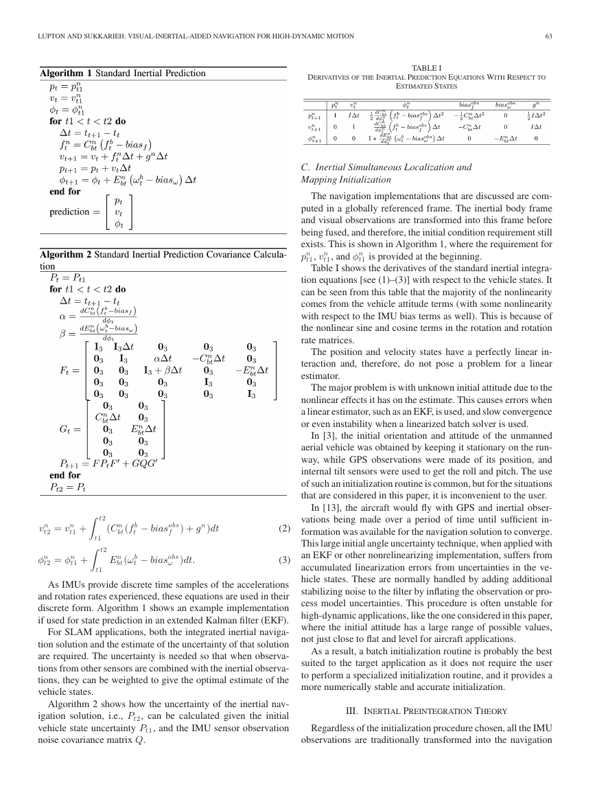
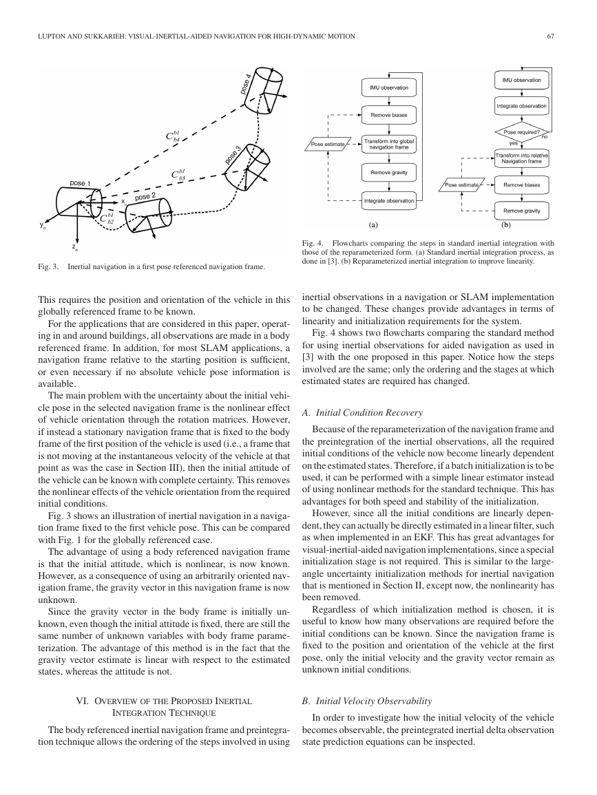
Fig. 3.
Inertial navigation in a first pose referenced navigation frame.
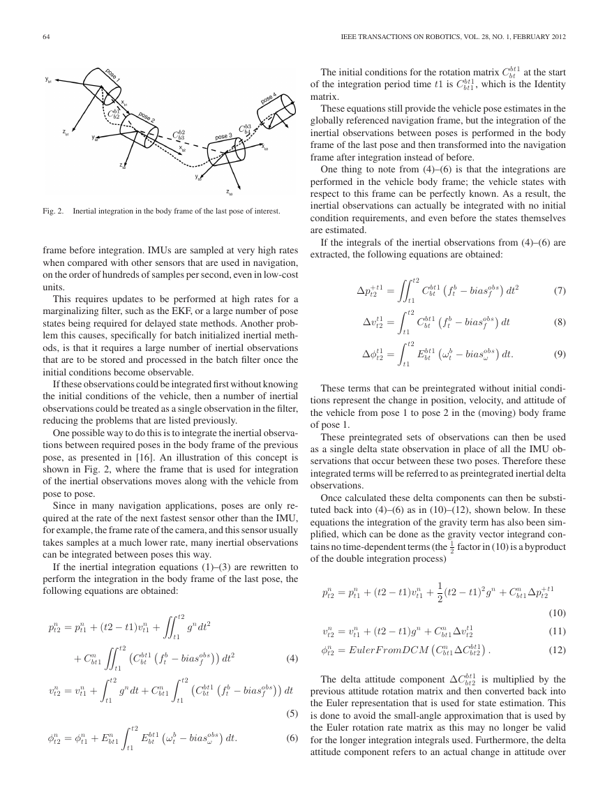
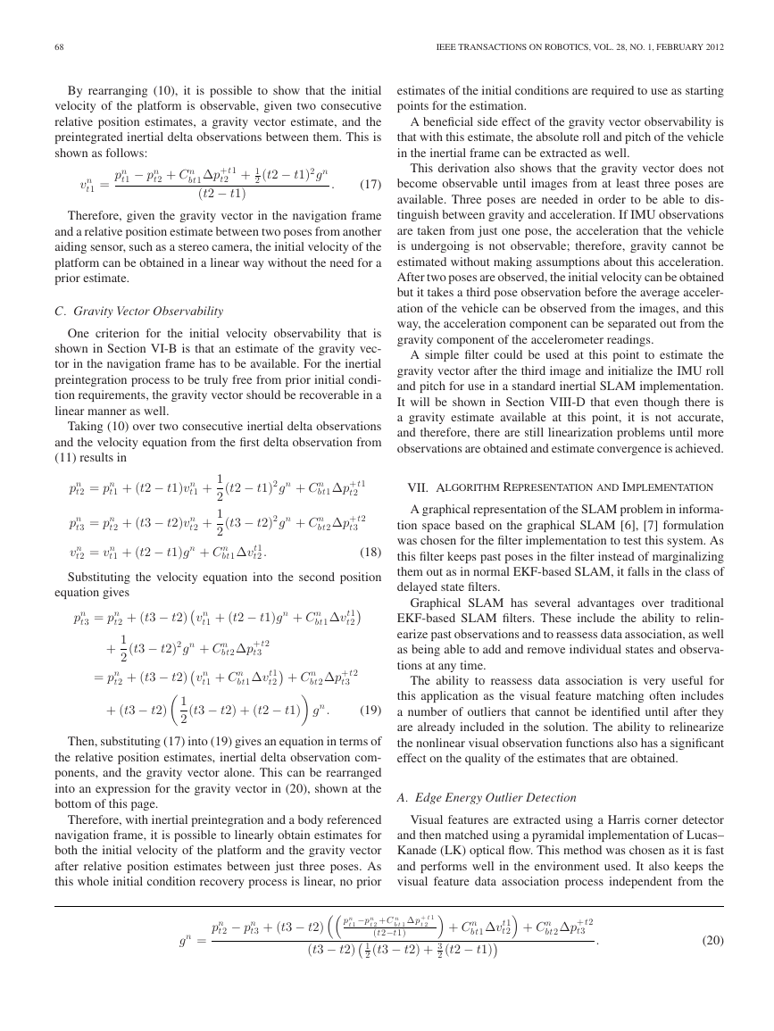
Fig. 4.
Flowcharts comparing the steps in standard inertial integration with
those of the reparameterized form. (a) Standard inertial integration process, as
done in [3]. (b) Reparameterized inertial integration to improve linearity.
This requires the position and orientation of the vehicle in this
globally referenced frame to be known.
For the applications that are considered in this paper, operat-
ing in and around buildings, all observations are made in a body
referenced frame. In addition, for most SLAM applications, a
navigation frame relative to the starting position is sufficient,
or even necessary if no absolute vehicle pose information is
available.
The main problem with the uncertainty about the initial vehi-
cle pose in the selected navigation frame is the nonlinear effect
of vehicle orientation through the rotation matrices. However,
if instead a stationary navigation frame that is fixed to the body
frame of the first position of the vehicle is used (i.e., a frame that
is not moving at the instantaneous velocity of the vehicle at that
point as was the case in Section III), then the initial attitude of
the vehicle can be known with complete certainty. This removes
the nonlinear effects of the vehicle orientation from the required
initial conditions.
Fig. 3 shows an illustration of inertial navigation in a naviga-
tion frame fixed to the first vehicle pose. This can be compared
with Fig. 1 for the globally referenced case.
The advantage of using a body referenced navigation frame
is that the initial attitude, which is nonlinear, is now known.
However, as a consequence of using an arbitrarily oriented nav-
igation frame, the gravity vector in this navigation frame is now
unknown.
Since the gravity vector in the body frame is initially un-
known, even though the initial attitude is fixed, there are still the
same number of unknown variables with body frame parame-
terization. The advantage of this method is in the fact that the
gravity vector estimate is linear with respect to the estimated
states, whereas the attitude is not.
inertial observations in a navigation or SLAM implementation
to be changed. These changes provide advantages in terms of
linearity and initialization requirements for the system.
Fig. 4 shows two flowcharts comparing the standard method
for using inertial observations for aided navigation as used in
[3] with the one proposed in this paper. Notice how the steps
involved are the same; only the ordering and the stages at which
estimated states are required has changed.
A. Initial Condition Recovery
Because of the reparameterization of the navigation frame and
the preintegration of the inertial observations, all the required
initial conditions of the vehicle now become linearly dependent
on the estimated states. Therefore, if a batch initialization is to be
used, it can be performed with a simple linear estimator instead
of using nonlinear methods for the standard technique. This has
advantages for both speed and stability of the initialization.
However, since all the initial conditions are linearly depen-
dent, they can actually be directly estimated in a linear filter, such
as when implemented in an EKF. This has great advantages for
visual-inertial-aided navigation implementations, since a special
initialization stage is not required. This is similar to the large-
angle uncertainty initialization methods for inertial navigation
that is mentioned in Section II, except now, the nonlinearity has
been removed.
Regardless of which initialization method is chosen, it is
useful to know how many observations are required before the
initial conditions can be known. Since the navigation frame is
fixed to the position and orientation of the vehicle at the first
pose, only the initial velocity and the gravity vector remain as
unknown initial conditions.
VI. OVERVIEW OF THE PROPOSED INERTIAL
B. Initial Velocity Observability
INTEGRATION TECHNIQUE
The body referenced inertial navigation frame and preintegra-
tion technique allows the ordering of the steps involved in using
In order to investigate how the initial velocity of the vehicle
becomes observable, the preintegrated inertial delta observation
state prediction equations can be inspected.
�
68
IEEE TRANSACTIONS ON ROBOTICS, VOL. 28, NO. 1, FEBRUARY 2012
By rearranging (10), it is possible to show that the initial
velocity of the platform is observable, given two consecutive
relative position estimates, a gravity vector estimate, and the
preintegrated inertial delta observations between them. This is
shown as follows:
t1 − pn
pn
2 (t2 − t1)2gn
t2 + 1
t2 + C n
.
(17)
t1 =
vn
bt1Δp+t1
(t2 − t1)
Therefore, given the gravity vector in the navigation frame
and a relative position estimate between two poses from another
aiding sensor, such as a stereo camera, the initial velocity of the
platform can be obtained in a linear way without the need for a
prior estimate.
C. Gravity Vector Observability
One criterion for the initial velocity observability that is
shown in Section VI-B is that an estimate of the gravity vec-
tor in the navigation frame has to be available. For the inertial
preintegration process to be truly free from prior initial condi-
tion requirements, the gravity vector should be recoverable in a
linear manner as well.
Taking (10) over two consecutive inertial delta observations
and the velocity equation from the first delta observation from
(11) results in
t2 = pn
pn
t3 = pn
pn
t1 +
(t2 − t1)2gn + C n
t1 + (t2 − t1)vn
1
2
(t3 − t2)2gn + C n
t2 + (t3 − t2)vn
1
2
t1 + (t2 − t1)gn + C n
bt1Δvt1
t2 .
t2 +
bt1Δp+t1
t2
bt2Δp+t2
t3
t2 = vn
vn
Substituting the velocity equation into the second position
(18)
equation gives
t3 = pn
pn
(t3 − t2)2gn + C n
t2 + (t3 − t2)
1
+
2
t2 + (t3 − t2)
= pn
+ (t3 − t2)
1
2
t1 + (t2 − t1)gn + C n
vn
bt1Δvt1
t2
bt2Δp+t2
t3
bt1Δvt1
t2
bt2Δp+t2
+ C n
t1 + C n
vn
t3
(t3 − t2) + (t2 − t1)
gn .
(19)
Then, substituting (17) into (19) gives an equation in terms of
the relative position estimates, inertial delta observation com-
ponents, and the gravity vector alone. This can be rearranged
into an expression for the gravity vector in (20), shown at the
bottom of this page.
Therefore, with inertial preintegration and a body referenced
navigation frame, it is possible to linearly obtain estimates for
both the initial velocity of the platform and the gravity vector
after relative position estimates between just three poses. As
this whole initial condition recovery process is linear, no prior
estimates of the initial conditions are required to use as starting
points for the estimation.
A beneficial side effect of the gravity vector observability is
that with this estimate, the absolute roll and pitch of the vehicle
in the inertial frame can be extracted as well.
This derivation also shows that the gravity vector does not
become observable until images from at least three poses are
available. Three poses are needed in order to be able to dis-
tinguish between gravity and acceleration. If IMU observations
are taken from just one pose, the acceleration that the vehicle
is undergoing is not observable; therefore, gravity cannot be
estimated without making assumptions about this acceleration.
After two poses are observed, the initial velocity can be obtained
but it takes a third pose observation before the average acceler-
ation of the vehicle can be observed from the images, and this
way, the acceleration component can be separated out from the
gravity component of the accelerometer readings.
A simple filter could be used at this point to estimate the
gravity vector after the third image and initialize the IMU roll
and pitch for use in a standard inertial SLAM implementation.
It will be shown in Section VIII-D that even though there is
a gravity estimate available at this point, it is not accurate,
and therefore, there are still linearization problems until more
observations are obtained and estimate convergence is achieved.
VII. ALGORITHM REPRESENTATION AND IMPLEMENTATION
A graphical representation of the SLAM problem in informa-
tion space based on the graphical SLAM [6], [7] formulation
was chosen for the filter implementation to test this system. As
this filter keeps past poses in the filter instead of marginalizing
them out as in normal EKF-based SLAM, it falls in the class of
delayed state filters.
Graphical SLAM has several advantages over traditional
EKF-based SLAM filters. These include the ability to relin-
earize past observations and to reassess data association, as well
as being able to add and remove individual states and observa-
tions at any time.
The ability to reassess data association is very useful for
this application as the visual feature matching often includes
a number of outliers that cannot be identified until after they
are already included in the solution. The ability to relinearize
the nonlinear visual observation functions also has a significant
effect on the quality of the estimates that are obtained.
A. Edge Energy Outlier Detection
Visual features are extracted using a Harris corner detector
and then matched using a pyramidal implementation of Lucas–
Kanade (LK) optical flow. This method was chosen as it is fast
and performs well in the environment used. It also keeps the
visual feature data association process independent from the
t2 − pn
pn
t3 + (t3 − t2)
gn =
p n
t 1
(t3 − t2)
−p n
b t 1 Δ p+ t 1
t 2 +C n
(t2−t1)
t 2
2 (t3 − t2) + 3
1
bt1Δvt1
+ C n
t2
2 (t2 − t1)
+ C n
bt2Δp+t2
t3
.
(20)
�



 2023年江西萍乡中考道德与法治真题及答案.doc
 2012年重庆南川中考生物真题及答案.doc
 2013年江西师范大学地理学综合及文艺理论基础考研真题.doc
 2020年四川甘孜小升初语文真题及答案I卷.doc
 2020年注册岩土工程师专业基础考试真题及答案.doc
 2023-2024学年福建省厦门市九年级上学期数学月考试题及答案.doc
 2021-2022学年辽宁省沈阳市大东区九年级上学期语文期末试题及答案.doc
 2022-2023学年北京东城区初三第一学期物理期末试卷及答案.doc
 2018上半年江西教师资格初中地理学科知识与教学能力真题及答案.doc
 2012年河北国家公务员申论考试真题及答案-省级.doc
 2020-2021学年江苏省扬州市江都区邵樊片九年级上学期数学第一次质量检测试题及答案.doc
 2022下半年黑龙江教师资格证中学综合素质真题及答案.doc