Programmer’s Reference
SiI9022A and SiI9024A Transmitter
Programming Interface (TPI)
Programmer‘s Reference
Document # SiI-PR-1064-A
�
SiI9022A and SiI9024A Transmitter Programming Interface (TPI)
Programmer’s Reference
Silicon Image, Inc.
September 2011
Copyright Notice
Copyright © 2009-2011 Silicon Image, Inc. All rights reserved. The contents of these materials contain proprietary and
confidential information (including trade secrets, copyright, and other Intellectual Property interests) of Silicon Image,
Inc. or its affiliates. All rights are reserved and contents, (in whole or in part) may not be reproduced, downloaded,
disseminated, published, or transferred in any form or by any means, except with the prior written permission of Silicon
Image, Inc. or its affiliates. You may not use these materials except only for your bona fide non-commercial evaluation of
your potential purchase of products and/or services from Silicon Image or its affiliates; and only in connection with your
purchase of products or services from Silicon Image or its affiliates, and only in accordance with the terms and conditions
stipulated. Copyright infringement is a violation of federal law subject to criminal and civil penalties. You have no right
to copy, modify, transfer, sublicense, publicly display, create derivative works of, distribute these materials, or otherwise
make these materials available, in whole or in part, to any third party.
Patents
The subject matter described herein may contain one or more inventions claimed in patents or patents pending owned by
Silicon Image, Inc. or its affiliates.
Trademark Acknowledgment
Silicon Image®, the Silicon Image logo, SteelVine®, Simplay®, Simplay HD®, the Simplay HD logo, Satalink®,
InstaPort®, the InstaPort Logo, and TMDS® are trademarks or registered trademarks of Silicon Image, Inc. in the United
States or other countries. HDMI® and the HDMI logo with High-Definition Multimedia Interface are trademarks or
registered trademarks of, and are used under license from, HDMI Licensing, LLC. in the United States or other countries.
MHL® and the MHL Logo are trademarks or registered trademarks of, and are used under license from, MHL, LLC. in
the United States or other countries. All other trademarks and registered trademarks are the property of their respective
owners in the United States or other countries. The absence of a trademark symbol does not constitute a waiver of Silicon
Image‘s trademark or other intellectual property rights with regard to a product name, logo or slogan.
Export Controlled Document
This document contains information subject to the Export Administration Regulations (EAR) and has a classification of
EAR99 or is controlled for Anti-Terrorism (AT) purposes. Transfer of this information by any means to an EAR Country
Group E:1 or foreign national thereof (whether in the U.S. or abroad) may require an export license or other approval
from the U.S. Department of Commerce. For more information, contact the Silicon Image Director of Global Trade
Compliance.
Further Information
To request other materials, documentation, and information, contact your local Silicon Image, Inc. sales office or visit the
Silicon Image, Inc. web site at www.siliconimage.com.
Revision History
Revision
Date
Comment
A
9/28/2011
First release; content extracted from PR-1032.
© 2009-2011 Silicon Image, Inc. All rights reserved.
ii
© 2009-2011 Silicon Image, Inc. All rights reserved.
CONFIDENTIAL
SiI-PR-1064-A
�
Silicon Image, Inc.
SiI9022A and SiI9024A Transmitter Programming Interface (TPI)
Programmer’s Reference
Contents
Overview ......................................................................................................................................................................... 1
Register Group Summary............................................................................................................................................. 2
Transmitter Programming Interface (TPI) ............................................................................................................... 2
Internal (Indexed) Registers ..................................................................................................................................... 3
Device-Specific Information ........................................................................................................................................ 3
SiI9022A and SiI9024A Transmitters ...................................................................................................................... 3
I2C Requirements ......................................................................................................................................................... 4
Summary of Host Software Tasks .................................................................................................................................... 5
Detailed Sequences ...................................................................................................................................................... 6
Initialization ............................................................................................................................................................. 6
Servicing a Hot Plug Event ...................................................................................................................................... 7
Changing Video Modes ........................................................................................................................................... 8
HDCP Authentication and Encryption ..................................................................................................................... 8
HDCP Revocation Check ........................................................................................................................................ 8
General Programming Registers ...................................................................................................................................... 9
Identification ................................................................................................................................................................ 9
Video Configuration .................................................................................................................................................. 10
Video Mode ........................................................................................................................................................... 10
Input Setup Operations .............................................................................................................................................. 13
DE Generator Register Set ......................................................................................................................................... 16
InfoFrame Data ...................................................................................................................................................... 18
Using xvYCC ......................................................................................................................................................... 20
System Control ...................................................................................................................................................... 22
Audio Configuration .................................................................................................................................................. 23
Configuring Audio using S/PDIF ........................................................................................................................... 23
Configuring Audio using I2S .................................................................................................................................. 25
Configuring Audio for DSD Format ...................................................................................................................... 28
Interrupt Service ............................................................................................................................................................ 29
Interrupt Enable Register ........................................................................................................................................... 29
Interrupt Status Register ............................................................................................................................................ 29
Interrupt Operation .................................................................................................................................................... 30
TPI System .................................................................................................................................................................... 32
Power State Control and Hot Plug Management ........................................................................................................... 33
Transmitter Power State Register ............................................................................................................................... 33
Hot vs Cold Wakeup Modes .................................................................................................................................. 34
Hot Plug Management ............................................................................................................................................... 34
Hot Plug Service Loop........................................................................................................................................... 34
Operating Sequences ............................................................................................................................................. 35
HDCP Implementation ................................................................................................................................................... 37
Control for HDCP ...................................................................................................................................................... 37
HDCP Operation .................................................................................................................................................... 38
HDCP Data Structure ............................................................................................................................................. 38
Auxiliary HDCP Registers ..................................................................................................................................... 40
SiI-PR-1064-A
© 2009-2011 Silicon Image, Inc. All rights reserved.
CONFIDENTIAL
iii
�
SiI9022A and SiI9024A Transmitter Programming Interface (TPI)
Programmer’s Reference
Silicon Image, Inc.
List of Figures
Figure 1. Transmitter Data Flow Paths ............................................................................................................................ 1
Figure 2. Transmitter TPI Register Interface to Host ....................................................................................................... 9
Figure 3. Input Bus Diagram for Different Formats....................................................................................................... 12
Figure 4. Transmitter Video Data with Sync Decoding ................................................................................................. 14
Figure 5. DE Generator Measurements .......................................................................................................................... 16
Figure 6. INT Pulse on Event other than HTPLG .......................................................................................................... 31
Figure 7. Setup Events ................................................................................................................................................... 35
Figure 8. Hot Plug and Interrupt Timing........................................................................................................................ 36
List of Tables
Table 1. Register Group Summary ................................................................................................................................... 2
Table 2. TPI Identification Registers (RO) ...................................................................................................................... 9
Table 3. Device ID Information ..................................................................................................................................... 10
Table 4. TPI Video Mode Data (R/W) ........................................................................................................................... 10
Table 5. TPI Input Bus and Pixel Repetition Data (R/W) .............................................................................................. 11
Table 6. 480p Mode Format Matching Example ........................................................................................................... 11
Table 7. TPI AVI Input and Output Format Data (R/W) ................................................................................................ 13
Table 8. Sync Register Configuration and Sync Monitoring Registers .......................................................................... 15
Table 9. TPI YC Input Mode Select (R/W) ................................................................................................................... 15
Table 10. Explicit Sync DE Generator Registers (TPI 0x60[7] = 0) ............................................................................. 17
Table 11. Embedded Sync Extraction Registers (TPI 0x60[7] = 1) ............................................................................... 18
Table 12. TPI AVI InfoFrame Data (R/W) ..................................................................................................................... 19
Table 13. TPI Miscellaneous InfoFrame Data (R/W) .................................................................................................... 21
Table 14. TPI System Control (R/W) ............................................................................................................................ 22
Table 15. TPI Audio Configuration Write Data (RW) ................................................................................................... 24
Table 16. Configuration of I2S Interface (RW) .............................................................................................................. 26
Table 17. Mapping of I2S Interface (RW) ...................................................................................................................... 26
Table 18. Stream Header Settings for I2S (RW) ............................................................................................................. 27
Table 19. TPI Interrupt Enable (R/W) ........................................................................................................................... 29
Table 20. TPI Interrupt Status (R/W) ............................................................................................................................. 29
Table 21. TPI Device Power State Control Data (R/W) ................................................................................................ 34
Table 22. Hot Plug Timing Requirements ...................................................................................................................... 36
Table 23. HPD to INT Delays ........................................................................................................................................ 36
Table 24. Mapping of HDCP Data to TPI Register Bits ................................................................................................ 37
Table 25. TPI Security Registers ................................................................................................................................... 39
Table 26. TPI HDCP Revision Data (RO) ..................................................................................................................... 40
Table 27. TPI KSV and V* Value Data (R/W) .............................................................................................................. 41
Table 28. TPI V* Value Readback Data (RO) ............................................................................................................... 41
Table 29. TPI Aksv Readback Data (RO) ...................................................................................................................... 41
iv
© 2009-2011 Silicon Image, Inc. All rights reserved.
CONFIDENTIAL
SiI-PR-1064-A
�
SiI9022A and SiI9024A Transmitter Programming Interface (TPI)
Programmer’s Reference
.
Overview
Silicon Image HDMI transmitter solutions merge independent video and audio streams for transmission over HDMI. To
do this, the transmitter employs a unique mechanism that allows host graphics and audio software to interact with the
HDMI transmitter.
All new devices implement a simplified interface and special logic that automates most HDMI functions. This
Transmitter Programming Interface (TPI) maps a concise set of registers into I2C address space that the host can readily
access.
TPI offers a significantly simplified operating scheme, using built-in hardware to handle tasks such as the following.
Secure operation is fully automatic on devices equipped with HDCP. With only a single-bit write, the device
establishes and maintains link security, interrupting the host only if the secure link is lost.
DDC arbitration is handled cleanly, allowing the host to simply request the bus and then fetch EDID information
directly – no need to program transfers into or out of a FIFO. Arbitration is handled even when link security is
enabled.
Complex audio setup is nearly eliminated. Hardware calculates N/CTS values and automatically sends out the
appropriate packet information with no setup needed.
All frequency-dependent internal settings, such as for PLLs, are derived automatically in hardware from the video
mode information that has been programmed.
In addition:
Devices still implement the standard Silicon Image register set used by legacy transmitters, for backwards
compatibility with special functions in existing code.
All devices implement an automated CEC controller, using the Silicon Image standard CEC Programming Interface
(CPI).
Many versions additionally support HDCP, implemented as part of the automated solution and requiring no host
intervention for normal operation.
This document describes the TPI programming solution for the following devices.
HDCP-enabled
Non HDCP-enabled
Upgrade to this existing
Version
SiI9024A Tx
Version
product
Application
SiI9022A Tx
SiI9022/24 Tx
HDMI Mobile
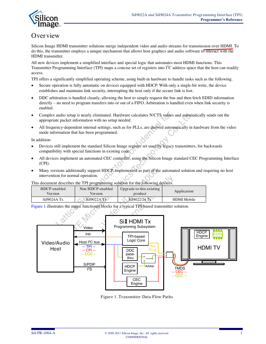
Figure 1 illustrates the major functional blocks for a typical TPI-based transmitter solution.
Figure 1. Transmitter Data Flow Paths
SiI-PR-1064-A
© 2009-2011 Silicon Image, Inc. All rights reserved.
CONFIDENTIAL
1
VideoVideo/AudioHostHDMI TVSiI HDMI TxIntr TMDS-- CEC ---- DDC --TPI-basedLogic CoreHost I2C busS/PDIFEDIDHotPlugHDCPEngineHDCPEngineI2S-- TPI ---- CPI ---- DDC --CECEngineDDCpass-thruArbiterProgramming Subsystem�
SiI9022A and SiI9024A Transmitter Programming Interface (TPI)
Programmer’s Reference
Register Group Summary
Transmitter Programming Interface (TPI)
Silicon Image, Inc.
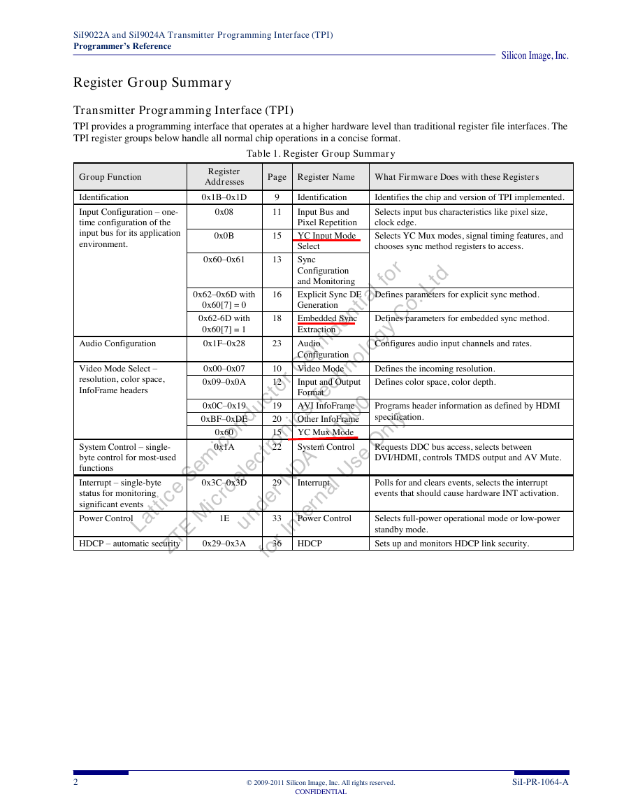
TPI provides a programming interface that operates at a higher hardware level than traditional register file interfaces. The
TPI register groups below handle all normal chip operations in a concise format.
Table 1. Register Group Summary
Page Register Name What Firmware Does with these Registers
9
11
15
13
18
23
10
12
19
20
15
22
Identification
Identifies the chip and version of TPI implemented.
Input Bus and
Pixel Repetition
Selects input bus characteristics like pixel size,
clock edge.
YC Input Mode
Select
Selects YC Mux modes, signal timing features, and
chooses sync method registers to access.
Sync
Configuration
and Monitoring
Explicit Sync DE
Generation
Embedded Sync
Extraction
Audio
Configuration
Defines parameters for explicit sync method.
Defines parameters for embedded sync method.
Configures audio input channels and rates.
Video Mode
Defines the incoming resolution.
Input and Output
Format
AVI InfoFrame
Other InfoFrame
Defines color space, color depth.
Programs header information as defined by HDMI
specification.
YC Mux Mode
System Control
Requests DDC bus access, selects between
DVI/HDMI, controls TMDS output and AV Mute.
Group Function
Identification
Input Configuration – one-
time configuration of the
input bus for its application
environment.
Register
Addresses
0x1B–0x1D
0x08
0x0B
0x60–0x61
0x62–0x6D with
16
0x60[7] = 0
0x62-6D with
0x60[7] = 1
Audio Configuration
0x1F–0x28
0x00–0x07
0x09–0x0A
0x0C–0x19
0xBF–0xDE
0x60
0x1A
Video Mode Select –
resolution, color space,
InfoFrame headers
System Control – single-
byte control for most-used
functions
Interrupt – single-byte
status for monitoring
significant events
0x3C–0x3D
29
Interrupt
Polls for and clears events, selects the interrupt
events that should cause hardware INT activation.
Power Control
1E
33
Power Control
Selects full-power operational mode or low-power
standby mode.
HDCP – automatic security
0x29–0x3A
36
HDCP
Sets up and monitors HDCP link security.
2
© 2009-2011 Silicon Image, Inc. All rights reserved.
CONFIDENTIAL
SiI-PR-1064-A
�
Silicon Image, Inc.
Internal (Indexed) Registers
SiI9022A and SiI9024A Transmitter Programming Interface (TPI)
Programmer’s Reference
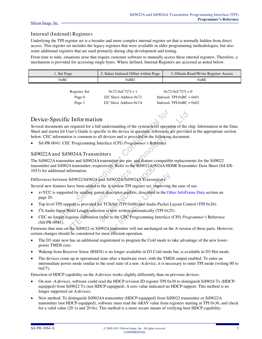
Underlying the TPI register set is a broader and more complex internal register set that is normally hidden from direct
access. This register set includes the legacy registers that were available in older programming methodologies, but also
some additional registers that are used primarily during chip development and testing.
From time to time, situations arise that require customer software to manually access these internal registers. Therefore, a
mechanism is provided for accessing single bytes. Where defined, Internal Registers are accessed as noted below.
1. Set Page
0xBC
2. Select Indexed Offset within Page
3. Obtain Read/Write Register Access
0xBD
0xBE
Register Set
0x72:0xC7[7] = 1
0x72:0xC7[7] = 0
Page 0
Page 1
I2C Slave Address 0x72
Indexed. TPI:0xBC = 0x01
I2C Slave Address 0x7A
Indexed. TPI:0xBC = 0x02
Device-Specific Information
Several documents are required for a full understanding of the system level operation of the chip. Information in the Data
Sheet and starter kit User‘s Guide is specific to the device in question; references are provided in the appropriate section
below. CEC information is common to all devices and is provided in the following document.
SiI-PR-0041: CEC Programming Interface (CPI) Programmer’s Reference
SiI9022A and SiI9024A Transmitters
The SiI9022A transmitter and SiI9024A transmitter are pin- and feature-compatible replacements for the SiI9022
transmitter and SiI9024 transmitter, respectively. Refer to the SiI9022A/9024A HDMI Transmitter Data Sheet (SiI-DS-
1053) for additional information.
Differences between SiI9022/SiI9024 and SiI9022A/SiI9024A Transmitters
Several new features have been added to the A version TPI register set, improving the ease of use.
xvYCC is supported by sending gamut descriptor packets, described in the Other InfoFrame Data section on
page 20.
Top level TPI support is provided for TClkSel (TPI 0x08) and Audio Packet Layout Control (TPI 0x26).
I2S Audio Input Word Length selection is now written automatically (TPI 0x25).
CEC no longer requires calibration (refer to the CEC Programming Interface (CPI) Programmer’s Reference
(SiI-PR-0041).
Firmware that runs on the SiI9022 or SiI9024 transmitter will run unchanged on the A version of these parts. However,
certain changes should be considered for most efficient operation.
The D3 state now has an additional requirement to program the Cold mode to take advantage of the new lower-
power TMDS core.
Wakeup from Receiver Sense (RSEN) is no longer available in D3 Cold mode but, is available in D3 Hot mode.
The devices come up in operational state after a hardware reset, with the TMDS output enabled. To enter an
intermediate power mode similar to the reset state of a non -A device, it is necessary to enter TPI mode (writing 00 to
0xC7).
Detection of HDCP capability on the A devices works slightly differently than on previous devices.
On non -A devices, software could read the HDCP revision ID register TPI 0x30 to distinguish SiI9024 Tx (HDCP-
equipped) from SiI9022 Tx (not HDCP-equipped). A zero value indicated no HDCP support. This method is no
longer supported on A devices.
New method: To distinguish SiI9024A transmitter (HDCP-equipped) from SiI9022 transmitter or SiI9022A
transmitter (not HDCP-equipped), software must read the AKSV value from registers starting at TPI 0x36, and check
for a valid value (20 1s and 20 0s). This method is a more secure means of verifying host HDCP capability.
SiI-PR-1064-A
© 2009-2011 Silicon Image, Inc. All rights reserved.
CONFIDENTIAL
3
�
SiI9022A and SiI9024A Transmitter Programming Interface (TPI)
Programmer’s Reference
Silicon Image, Inc.
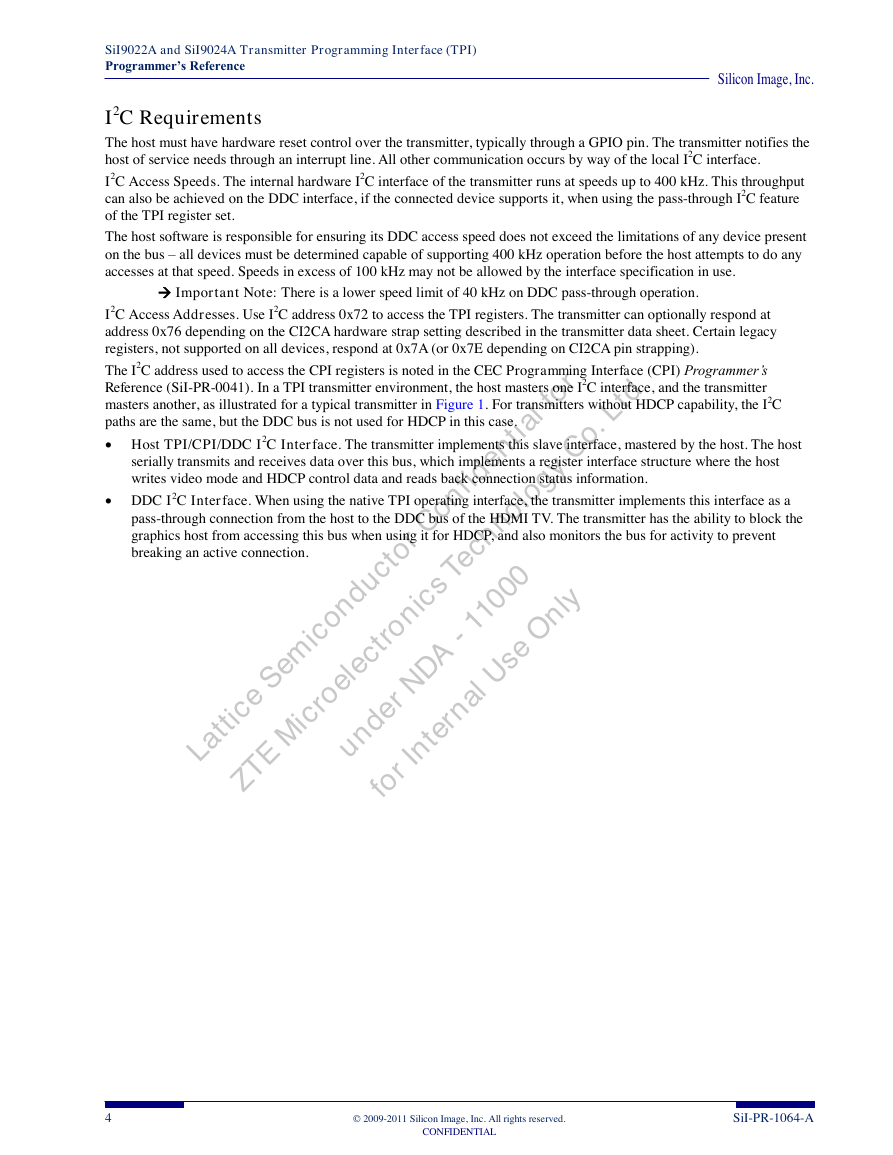
I2C Requirements
The host must have hardware reset control over the transmitter, typically through a GPIO pin. The transmitter notifies the
host of service needs through an interrupt line. All other communication occurs by way of the local I2C interface.
I2C Access Speeds. The internal hardware I2C interface of the transmitter runs at speeds up to 400 kHz. This throughput
can also be achieved on the DDC interface, if the connected device supports it, when using the pass-through I2C feature
of the TPI register set.
The host software is responsible for ensuring its DDC access speed does not exceed the limitations of any device present
on the bus – all devices must be determined capable of supporting 400 kHz operation before the host attempts to do any
accesses at that speed. Speeds in excess of 100 kHz may not be allowed by the interface specification in use.
Important Note: There is a lower speed limit of 40 kHz on DDC pass-through operation.
I2C Access Addresses. Use I2C address 0x72 to access the TPI registers. The transmitter can optionally respond at
address 0x76 depending on the CI2CA hardware strap setting described in the transmitter data sheet. Certain legacy
registers, not supported on all devices, respond at 0x7A (or 0x7E depending on CI2CA pin strapping).
The I2C address used to access the CPI registers is noted in the CEC Programming Interface (CPI) Programmer’s
Reference (SiI-PR-0041). In a TPI transmitter environment, the host masters one I2C interface, and the transmitter
masters another, as illustrated for a typical transmitter in Figure 1. For transmitters without HDCP capability, the I2C
paths are the same, but the DDC bus is not used for HDCP in this case.
Host TPI/CPI/DDC I2C Interface. The transmitter implements this slave interface, mastered by the host. The host
serially transmits and receives data over this bus, which implements a register interface structure where the host
writes video mode and HDCP control data and reads back connection status information.
DDC I2C Interface. When using the native TPI operating interface, the transmitter implements this interface as a
pass-through connection from the host to the DDC bus of the HDMI TV. The transmitter has the ability to block the
graphics host from accessing this bus when using it for HDCP, and also monitors the bus for activity to prevent
breaking an active connection.
4
© 2009-2011 Silicon Image, Inc. All rights reserved.
CONFIDENTIAL
SiI-PR-1064-A
�



 2023年江西萍乡中考道德与法治真题及答案.doc
 2012年重庆南川中考生物真题及答案.doc
 2013年江西师范大学地理学综合及文艺理论基础考研真题.doc
 2020年四川甘孜小升初语文真题及答案I卷.doc
 2020年注册岩土工程师专业基础考试真题及答案.doc
 2023-2024学年福建省厦门市九年级上学期数学月考试题及答案.doc
 2021-2022学年辽宁省沈阳市大东区九年级上学期语文期末试题及答案.doc
 2022-2023学年北京东城区初三第一学期物理期末试卷及答案.doc
 2018上半年江西教师资格初中地理学科知识与教学能力真题及答案.doc
 2012年河北国家公务员申论考试真题及答案-省级.doc
 2020-2021学年江苏省扬州市江都区邵樊片九年级上学期数学第一次质量检测试题及答案.doc
 2022下半年黑龙江教师资格证中学综合素质真题及答案.doc