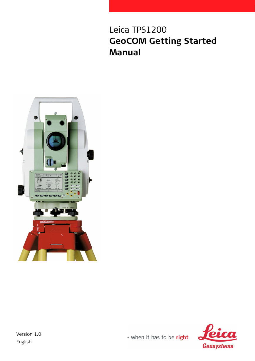
Leica TPS1200
GeoCOM Getting Started
Manual
Version 1.0
English
�
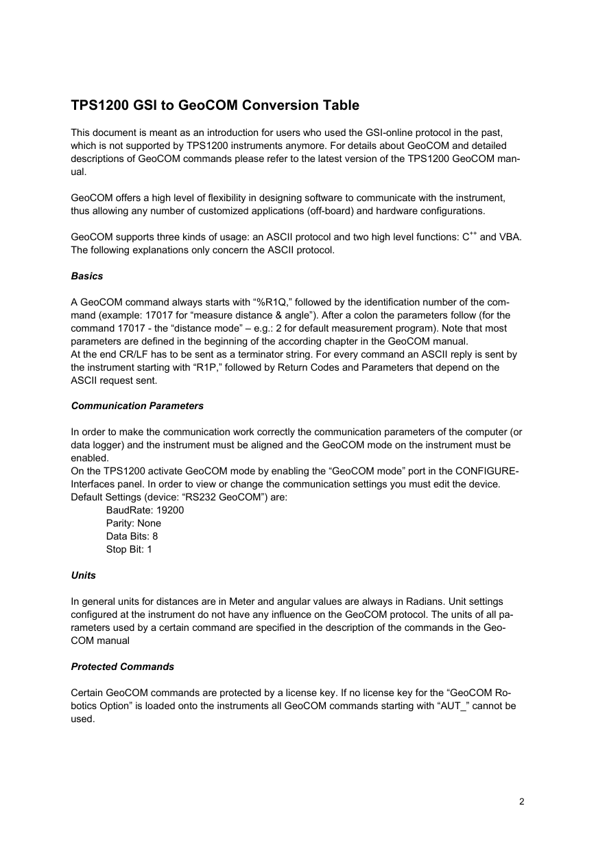
TPS1200 GSI to GeoCOM Conversion Table
This document is meant as an introduction for users who used the GSI-online protocol in the past,
which is not supported by TPS1200 instruments anymore. For details about GeoCOM and detailed
descriptions of GeoCOM commands please refer to the latest version of the TPS1200 GeoCOM man-
ual.
GeoCOM offers a high level of flexibility in designing software to communicate with the instrument,
thus allowing any number of customized applications (off-board) and hardware configurations.
GeoCOM supports three kinds of usage: an ASCII protocol and two high level functions: C++ and VBA.
The following explanations only concern the ASCII protocol.
Basics
A GeoCOM command always starts with “%R1Q,” followed by the identification number of the com-
mand (example: 17017 for “measure distance & angle”). After a colon the parameters follow (for the
command 17017 - the “distance mode” – e.g.: 2 for default measurement program). Note that most
parameters are defined in the beginning of the according chapter in the GeoCOM manual.
At the end CR/LF has to be sent as a terminator string. For every command an ASCII reply is sent by
the instrument starting with “R1P,” followed by Return Codes and Parameters that depend on the
ASCII request sent.
Communication Parameters
In order to make the communication work correctly the communication parameters of the computer (or
data logger) and the instrument must be aligned and the GeoCOM mode on the instrument must be
enabled.
On the TPS1200 activate GeoCOM mode by enabling the “GeoCOM mode” port in the CONFIGURE-
Interfaces panel. In order to view or change the communication settings you must edit the device.
Default Settings (device: “RS232 GeoCOM”) are:
BaudRate: 19200
Parity: None
Data Bits: 8
Stop Bit: 1
Units
In general units for distances are in Meter and angular values are always in Radians. Unit settings
configured at the instrument do not have any influence on the GeoCOM protocol. The units of all pa-
rameters used by a certain command are specified in the description of the commands in the Geo-
COM manual
Protected Commands
Certain GeoCOM commands are protected by a license key. If no license key for the “GeoCOM Ro-
botics Option” is loaded onto the instruments all GeoCOM commands starting with “AUT_” cannot be
used.
2
�
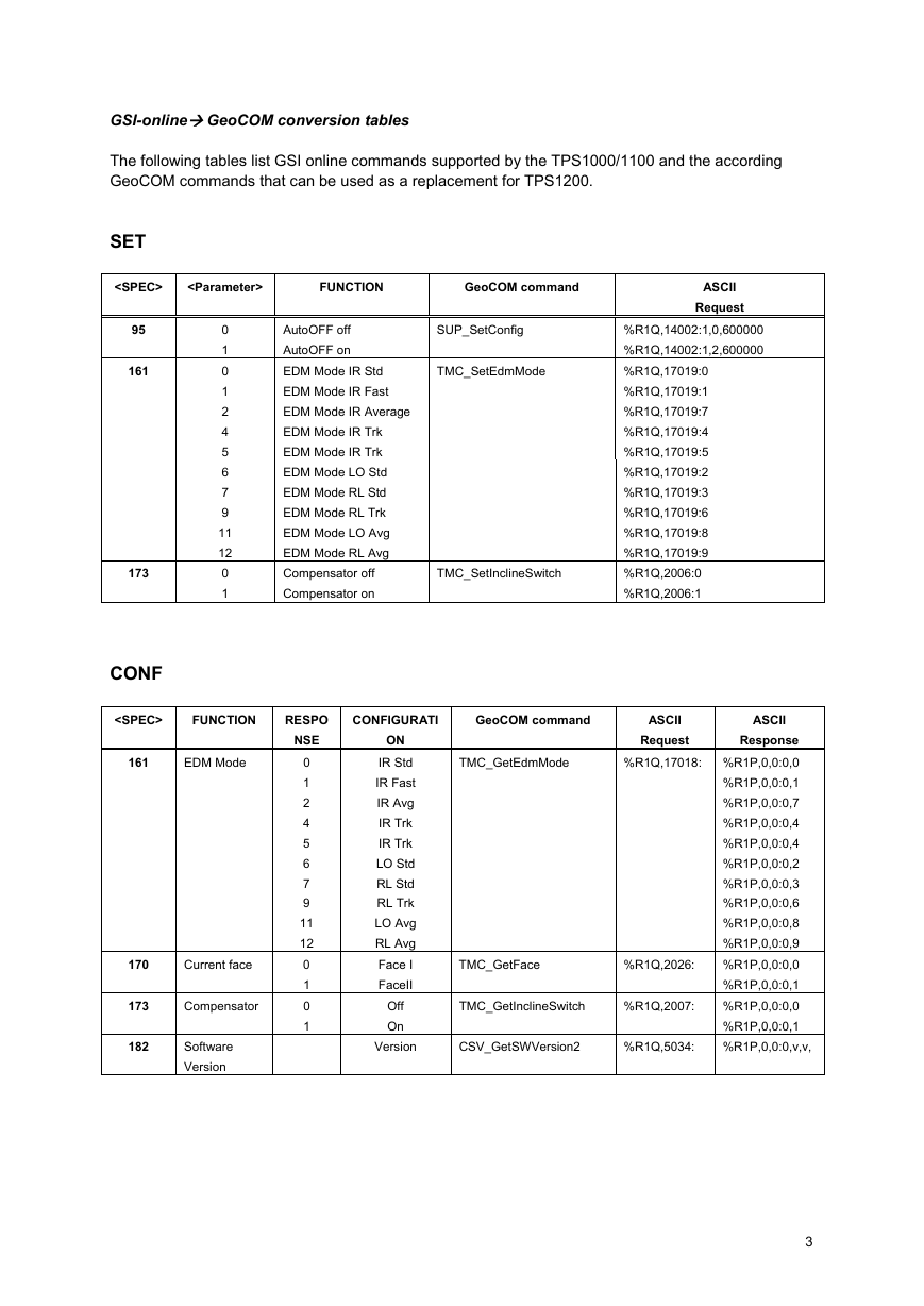
GSI-online GeoCOM conversion tables
The following tables list GSI online commands supported by the TPS1000/1100 and the according
GeoCOM commands that can be used as a replacement for TPS1200.
SET
GeoCOM command
FUNCTION
95
161
173
CONF
161
170
173
182
ASCII
Request
0
1
0
1
2
4
5
6
7
9
11
12
0
1
AutoOFF off
AutoOFF on
EDM Mode IR Std
EDM Mode IR Fast
EDM Mode IR Average
EDM Mode IR Trk
EDM Mode IR Trk
EDM Mode LO Std
EDM Mode RL Std
EDM Mode RL Trk
EDM Mode LO Avg
EDM Mode RL Avg
Compensator off
Compensator on
SUP_SetConfig
TMC_SetEdmMode
TMC_SetInclineSwitch
%R1Q,14002:1,0,600000
%R1Q,14002:1,2,600000
%R1Q,17019:0
%R1Q,17019:1
%R1Q,17019:7
%R1Q,17019:4
%R1Q,17019:5
%R1Q,17019:2
%R1Q,17019:3
%R1Q,17019:6
%R1Q,17019:8
%R1Q,17019:9
%R1Q,2006:0
%R1Q,2006:1
FUNCTION
EDM Mode
Current face
Compensator
Software
Version
RESPO
NSE
0
1
2
4
5
6
7
9
11
12
0
1
0
1
CONFIGURATI
GeoCOM command
ON
IR Std
IR Fast
IR Avg
IR Trk
IR Trk
LO Std
RL Std
RL Trk
LO Avg
RL Avg
Face I
FaceII
Off
On
Version
TMC_GetEdmMode
TMC_GetFace
TMC_GetInclineSwitch
CSV_GetSWVersion2
ASCII
ASCII
Request
Response
%R1Q,17018: %R1P,0,0:0,0
%R1P,0,0:0,1
%R1P,0,0:0,7
%R1P,0,0:0,4
%R1P,0,0:0,4
%R1P,0,0:0,2
%R1P,0,0:0,3
%R1P,0,0:0,6
%R1P,0,0:0,8
%R1P,0,0:0,9
%R1P,0,0:0,0
%R1Q,2026:
%R1P,0,0:0,1
%R1P,0,0:0,0
%R1Q,2007:
%R1P,0,0:0,1
%R1Q,5034:
%R1P,0,0:0,v,v,
3
�
PUT
FUNCTION
GeoCOM command
Hz Angle
Prism Constant
Station Easting
Station Northing
Station Elevation
Reflector Height
Instrument Height
TMC_SetOrientation
TMC_SetPrismCorr
TMC_SetStation
TMC_SetStation
TMC_SetStation
TMC_SetHeight
TMC_SetStation
21
58
84
85
86
87
88
GET
FUNCTION
GeoCOM command
ASCII
Request
%R1Q,2113 :HzOrientation
%R1Q,2024:PrismCorr
%R1Q,2010:E0,N0,H0,Hi
%R1Q,2010:E0,N0,H0,Hi
%R1Q,2010:E0,N0,H0,Hi
%R1Q,2012:Height
%R1Q,2010:E0,N0,H0,Hi
CSV_GetInstrumentNo
CSV_GetInstrumentNa
me
CSV_GetDateTIme
ASCII
Request
%R1Q,5003:
%R1Q,5004:
%R1Q,5008:
%R1Q,2107:
%R1Q,17017:2
%R1Q,2107:
%R1Q,17017:2
%R1Q,2107:
%R1Q,17017:2
TMC_GetSimpleMea
BAP_MeasDistAngle
TMC_GetSimpleMea
BAP_MeasDistAngle
TMC_GetSimple Mea
BAP_MeasDistAngle
TMC_GetSlopeDistCorr %R1Q,2126:
TMC_GetPrismCorr
%R1Q,2023:
TMC_GetSlopeDistCorr %R1Q,2126:
TMC_DoMeasure
%R1Q,2008:1
%R1Q,2116:
TMC_GetSimpleCoordin
ate
TMC_DoMeasure
TMC_GetSimpleCoordin
ate
TMC_DoMeasure
TMC_GetSimpleCoordin
ate
TMC_GetStation
TMC_GetStation
TMC_GetStation
TMC_GetHeight
TMC_GetStation
%R1Q,2009:
%R1Q,2009:
%R1Q,2009:
%R1Q,2011:
%R1Q,2009:
%R1Q,2008:1
%R1Q,2116:
%R1Q,2008:1
%R1Q,2116:
Serial Number
Instrument Type
Time
Horizontal Angle
Vertical Angle
Slope Distance
PPM / mm
Prism constant
PPM
Target Easting
Target Northing
Target Elevation
Station Easting
Station Northing
Station Height
Reflector Height
Instrument Height
12
13
19
I/21
M/22
I/22
M/22
I/31
M/31
51
58
59
I/81
I/82
I/83
84
85
86
87
88
ASCII
Response
%R1P,0,0:0, SerialNo
%R1P,0,0:0,Name
%R1P,0,0:0,Year],Month,Day,Hour,Minute
,Second
%R1P,0,0:0,Hz,V,SlopeDistance
%R1P,0,0:0, dHz, dV, dDist,DistMode
%R1P,0,0:0,Hz,V,SlopeDistance
%R1P,0,0:0, dHz, dV, dDist,DistMode
%R1P,0,0:0,Hz,V,SlopeDistance
%R1P,0,0:0, dHz, dV, dDist,DistMode
%R1P,0,0:0,total_Ppm,PrismCorr
%R1P,0,0:0,PrismCorr
%R1P,0,0:0,total_Ppm,PrismCorr
%R1P,0,0:0
%R1P,0,0:0,E,N,H
%R1P,0,0:0
%R1P,0,0:0,E,N,H
%R1P,0,0:0
%R1P,0,0:0,E,N,H
%R1P,0,0:0,E0,N0,H0,Hi
%R1P,0,0:0,E0,N0,H0,Hi
%R1P,0,0:0,E0,N0,H0,Hi
%R1P,0,0:0,Height
%R1P,0,0:0,E0,N0,H0,Hi
4
�
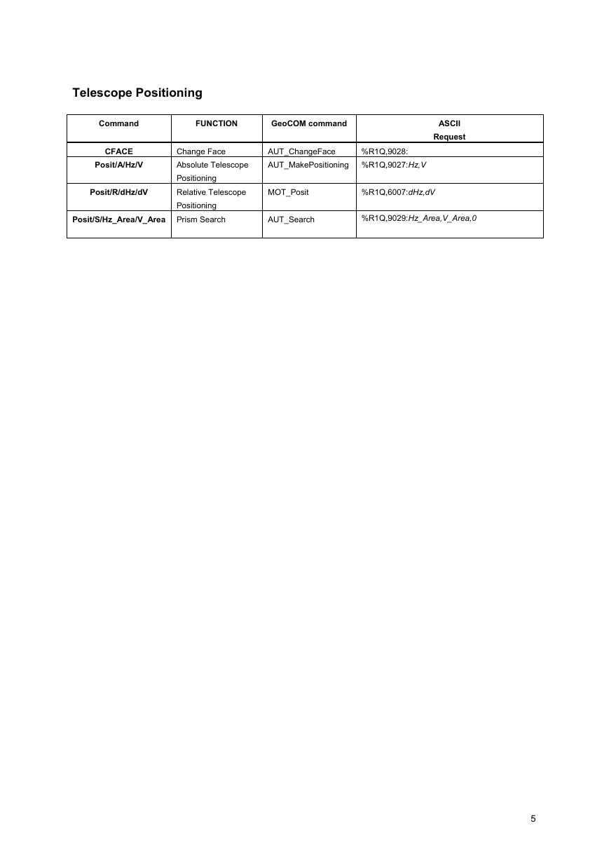
Telescope Positioning
Command
CFACE
Posit/A/Hz/V
Posit/R/dHz/dV
FUNCTION
GeoCOM command
ASCII
Request
Change Face
Absolute Telescope
Positioning
Relative Telescope
Positioning
AUT_ChangeFace
AUT_MakePositioning %R1Q,9027:Hz,V
%R1Q,9028:
MOT_Posit
%R1Q,6007:dHz,dV
Posit/S/Hz_Area/V_Area Prism Search
AUT_Search
%R1Q,9029:Hz_Area,V_Area,0
5
�
Whether you want to survey a parcel of land or objects on a
construction site, determine measured points on facades or in
rooms, gather the coordinates of a bridge or a tunnel– Leica
Geosystems’ surveying instruments provide the right solution for
every application.
They unite reliable results with easy operation and user-friendly
applications. They are designed to meet your specific
requirements. Modern technology enables you to work fast and
productively, thanks to the straightforward and clearly structured
range of functions.
When it has to be right.
Illustrations, descriptions and technical data are subject to change without notice.
Printed in Switzerland – Copyright Leica Geosystems AG, 2006
754954-1.0.1en
Leica Geosystems AG
Heinrich Wild Strasse
CH-9435 Heerbrugg
Switzerland
Phone +41 71 727 31 31
www.leica-geosystems.com
�




 2023年江西萍乡中考道德与法治真题及答案.doc
 2012年重庆南川中考生物真题及答案.doc
 2013年江西师范大学地理学综合及文艺理论基础考研真题.doc
 2020年四川甘孜小升初语文真题及答案I卷.doc
 2020年注册岩土工程师专业基础考试真题及答案.doc
 2023-2024学年福建省厦门市九年级上学期数学月考试题及答案.doc
 2021-2022学年辽宁省沈阳市大东区九年级上学期语文期末试题及答案.doc
 2022-2023学年北京东城区初三第一学期物理期末试卷及答案.doc
 2018上半年江西教师资格初中地理学科知识与教学能力真题及答案.doc
 2012年河北国家公务员申论考试真题及答案-省级.doc
 2020-2021学年江苏省扬州市江都区邵樊片九年级上学期数学第一次质量检测试题及答案.doc
 2022下半年黑龙江教师资格证中学综合素质真题及答案.doc