PC/104 Specification
Version 2.5
November 2003
Please Note
This specification is subject to change without notice. While every effort has been made to
ensure the accuracy of the material contained within this document, the PC/104 Embedded
Consortium shall under no circumstances be liable for incidental or consequential damages or
related expenses resulting from the use of this specification. If errors are found, please notify
the PC/104 Embedded Consortium.
PC/104 is a trademark of the PC/104 Embedded Consortium. All other marks are the property
of their respective companies.
Copyright 1992-2003, PC/104 Embedded Consortium
PC/104 Specification Version 2.5 — Page i
�
PC/104 Specification Version 2.5 — Page ii
�
REVISION HISTORY
Version 1.0, March 1992 - Initial release.
Version 2.1, July 1994 - Revised specification incorporating changes to conform with IEEE
P996.1 draft version D1.00:
a. Changed bus options. Eliminated the "option 2" configurations having right-angle P1 and P2
connectors. Created new "option 2" configurations similar to "option 1,” but without the
stackthrough pins. Added a statement indicating that a P2 connector may be included on 8-
bit modules, if desired.
b. Added two additional mounting holes to 8-bit bus versions, making the mounting hole
patterns of both 8- and 16-bit modules identical.
c. Added an I/O connector region along the bus edge of the module.
d. Increased widths of I/O mating-connector regions from 0.4" to 0.5".
e. Changed lengths of I/O mating-connector regions so that their edges align with the outer
edges of the annular rings of adjacent mounting holes.
f. Reduced the bus drive requirement on the signals that had been specified at 6 mA to 4 mA.
g. Added specification of module power requirements.
h. In Appendix C, Section 3, changed minimum value of pullup resistance on shared interrupt
line from 10K to 15K ohms.
i. Added a section defining levels of PC/104 conformance.
Version 2.2, September 1994
a. Added correction sheet showing revised schematic for Appendix C.
Version 2.3, June 1996
a. Incorporated correction to Appendix C schematic.
b. Changed P2 connector Pin 1 designation in 16-bit module dimension drawings.
c. Added metric dimensions, including metric versions of module dimension drawings.
d. Minor formatting changes.
Version 2.4, August 2001
a. Added Appendix D Connector Specifications.
b. Removed all specific company references.
c. Corrected Consortium address and phone numbers
d. Added new reference for ISA specification
e. Cleaned up mechanical drawings
PC/104 Specification Version 2.5 — Page iii
�
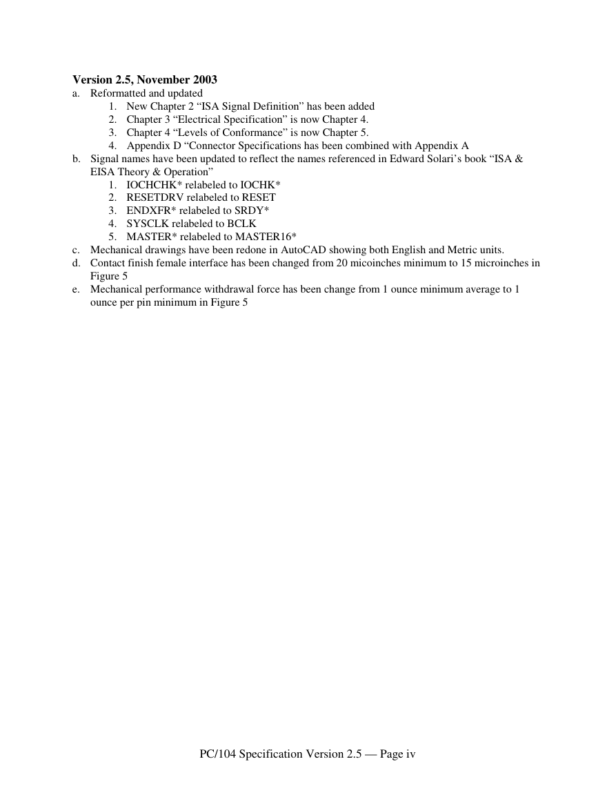
Version 2.5, November 2003
a. Reformatted and updated
1. New Chapter 2 “ISA Signal Definition” has been added
2. Chapter 3 “Electrical Specification” is now Chapter 4.
3. Chapter 4 “Levels of Conformance” is now Chapter 5.
4. Appendix D “Connector Specifications has been combined with Appendix A
b. Signal names have been updated to reflect the names referenced in Edward Solari’s book “ISA &
EISA Theory & Operation”
1. IOCHCHK* relabeled to IOCHK*
2. RESETDRV relabeled to RESET
3. ENDXFR* relabeled to SRDY*
4. SYSCLK relabeled to BCLK
5. MASTER* relabeled to MASTER16*
c. Mechanical drawings have been redone in AutoCAD showing both English and Metric units.
d. Contact finish female interface has been changed from 20 micoinches minimum to 15 microinches in
Figure 5
e. Mechanical performance withdrawal force has been change from 1 ounce minimum average to 1
ounce per pin minimum in Figure 5
PC/104 Specification Version 2.5 — Page iv
�
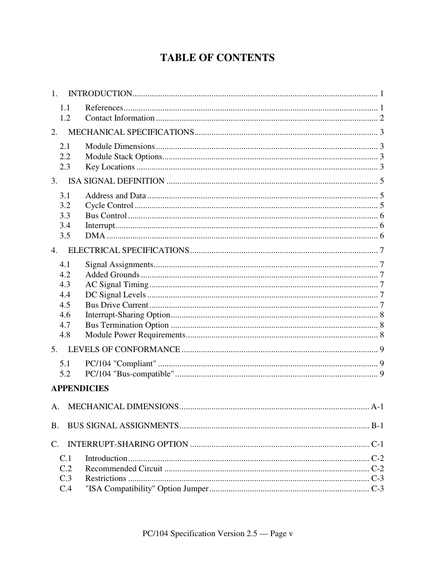
TABLE OF CONTENTS
1.
INTRODUCTION................................................................................................................... 1
1.1
1.2
References....................................................................................................................... 1
Contact Information ........................................................................................................ 2
2. MECHANICAL SPECIFICATIONS...................................................................................... 3
2.1 Module Dimensions ........................................................................................................ 3
2.2 Module Stack Options..................................................................................................... 3
2.3
Key Locations ................................................................................................................. 3
3.
ISA SIGNAL DEFINITION ................................................................................................... 5
3.1
3.2
3.3
3.4
3.5
Address and Data ............................................................................................................ 5
Cycle Control .................................................................................................................. 5
Bus Control ..................................................................................................................... 6
Interrupt........................................................................................................................... 6
DMA ............................................................................................................................... 6
4. ELECTRICAL SPECIFICATIONS........................................................................................ 7
Signal Assignments......................................................................................................... 7
4.1
Added Grounds ............................................................................................................... 7
4.2
AC Signal Timing........................................................................................................... 7
4.3
DC Signal Levels ............................................................................................................ 7
4.4
Bus Drive Current ........................................................................................................... 7
4.5
Interrupt-Sharing Option................................................................................................. 8
4.6
4.7
Bus Termination Option ................................................................................................. 8
4.8 Module Power Requirements.......................................................................................... 8
5. LEVELS OF CONFORMANCE ............................................................................................ 9
5.1
5.2
PC/104 "Compliant" ....................................................................................................... 9
PC/104 "Bus-compatible" ............................................................................................... 9
APPENDICIES
A. MECHANICAL DIMENSIONS......................................................................................... A-1
B. BUS SIGNAL ASSIGNMENTS......................................................................................... B-1
C. INTERRUPT-SHARING OPTION .................................................................................... C-1
C.1
Introduction................................................................................................................. C-2
C.2 Recommended Circuit ................................................................................................ C-2
C.3 Restrictions ................................................................................................................. C-3
"ISA Compatibility" Option Jumper........................................................................... C-3
C.4
PC/104 Specification Version 2.5 — Page v
�
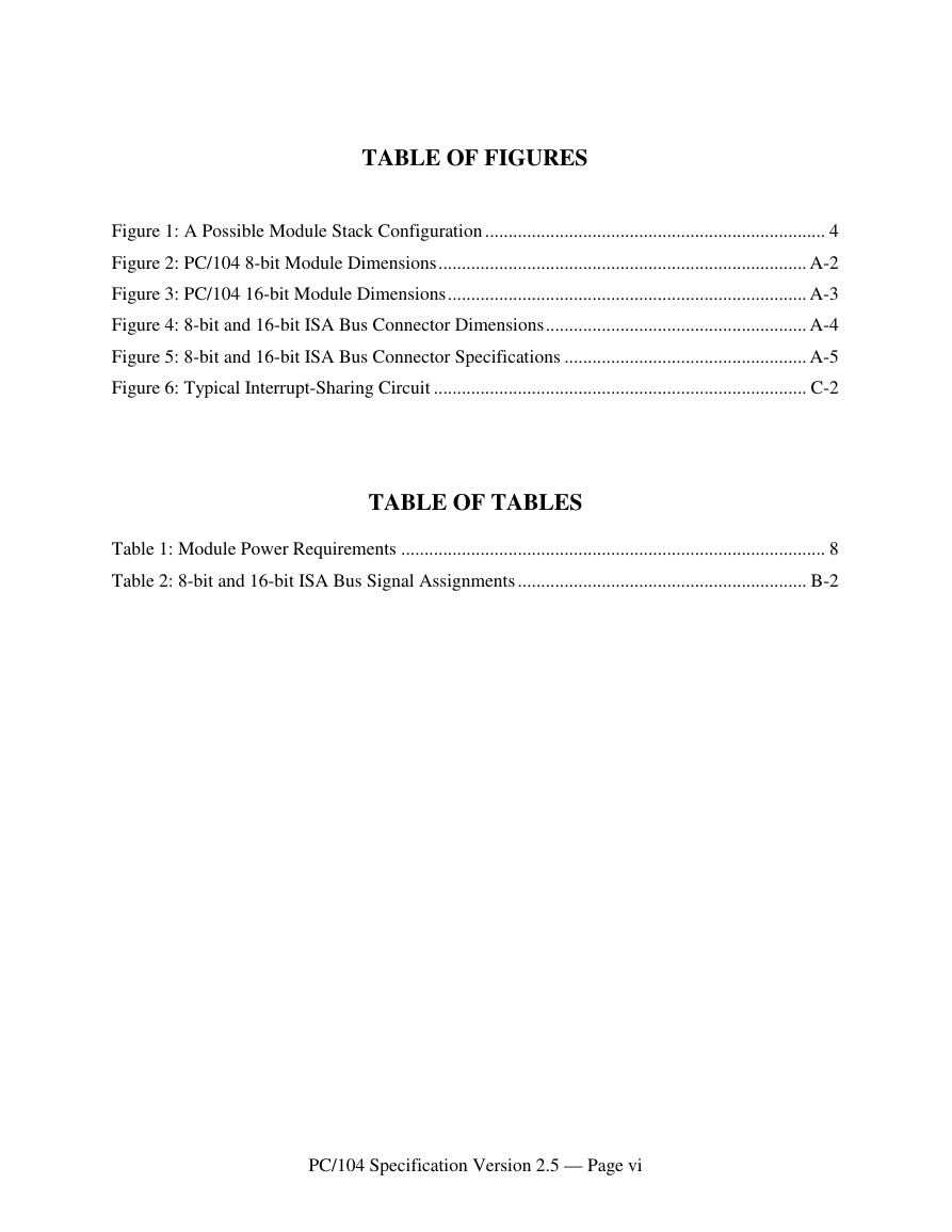
TABLE OF FIGURES
Figure 1: A Possible Module Stack Configuration ......................................................................... 4
Figure 2: PC/104 8-bit Module Dimensions............................................................................... A-2
Figure 3: PC/104 16-bit Module Dimensions............................................................................. A-3
Figure 4: 8-bit and 16-bit ISA Bus Connector Dimensions........................................................ A-4
Figure 5: 8-bit and 16-bit ISA Bus Connector Specifications .................................................... A-5
Figure 6: Typical Interrupt-Sharing Circuit ................................................................................ C-2
Table 1: Module Power Requirements ........................................................................................... 8
TABLE OF TABLES
Table 2: 8-bit and 16-bit ISA Bus Signal Assignments .............................................................. B-2
PC/104 Specification Version 2.5 — Page vi
�
PC/104 SPECIFICATION
Version 2.5 – March 2003
INTRODUCTION
1.
While the PC and PC/AT architectures have become extremely popular in both general purpose
(desktop) and dedicated (non-desktop) applications, its use in embedded microcomputer
applications has been limited due to the large size of standard PC and PC/AT motherboards and
expansion cards.
This document supplies the mechanical and electrical specifications for a compact version of the
ISA (PC and PC/AT) bus, optimized for the unique requirements of embedded systems
applications. The specification is herein referred to as "PC/104," based on the 104 signal
contacts on the two bus connectors (64 pins on P1, plus 40 pins on P2).
Briefly, the needs of embedded applications have been satisfied by PC/104, through the
following key differences from standard ISA bus:
n Reducing the form-factor, to 3.550 by 3.775 inches (90 by 96 mm).
n Eliminating the need for backplanes or card cages, through its self-stacking bus.
n Minimizing component count and power consumption (to typically 1-2 Watts per module),
by reducing required bus drive on most signals to 4 mA.
PC/104 specifies two module versions — 8-bit and 16-bit — which correspond to the PC and
PC/AT bus implementations, respectively.
1.1 References
The remainder of this specification covers the differences from the ISA bus as detailed in
Edward Solari’s book ISA and EISA Theory and Operation published by Annabooks.
Designers of modules and systems based on PC/104 should be familiar with the ISA
specification. It is available from:
Annabooks
12860 Danielson Court
Poway, CA USA 92064
Tel 800.462.1042 or 858.435.2000
Fax 858.391.5616
On the web at http://www.annabooks.com
PC/104 Specification Version 2.5 — Page 1
�
1.2 Contact Information
If errors are found in this document, please send a written copy of the suggested corrections to:
PC/104 Embedded Consortium
P.O. Box 78008
San Francisco, CA 94107-8008
Tel 415.243.2104
Fax 415.836.9094
E-mail info@pc104.org
Website http://www.pc104.org
PC/104 Specification Version 2.5 — Page 2
�




 2023年江西萍乡中考道德与法治真题及答案.doc
 2012年重庆南川中考生物真题及答案.doc
 2013年江西师范大学地理学综合及文艺理论基础考研真题.doc
 2020年四川甘孜小升初语文真题及答案I卷.doc
 2020年注册岩土工程师专业基础考试真题及答案.doc
 2023-2024学年福建省厦门市九年级上学期数学月考试题及答案.doc
 2021-2022学年辽宁省沈阳市大东区九年级上学期语文期末试题及答案.doc
 2022-2023学年北京东城区初三第一学期物理期末试卷及答案.doc
 2018上半年江西教师资格初中地理学科知识与教学能力真题及答案.doc
 2012年河北国家公务员申论考试真题及答案-省级.doc
 2020-2021学年江苏省扬州市江都区邵樊片九年级上学期数学第一次质量检测试题及答案.doc
 2022下半年黑龙江教师资格证中学综合素质真题及答案.doc