logo资料库

TMS320C6000 McBSP使用说明.pdf

第1页 / 共88页
第2页 / 共88页
第3页 / 共88页
第4页 / 共88页
第5页 / 共88页
第6页 / 共88页
第7页 / 共88页
第8页 / 共88页
资料共88页,剩余部分请下载后查看
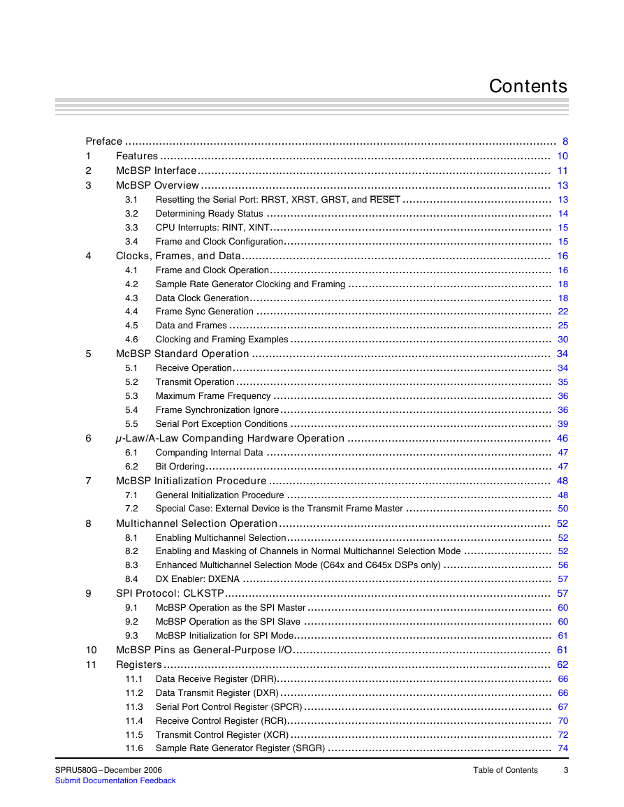
Table of Contents
Preface
1 Features
2 McBSP Interface
3 McBSP Overview
3.1 Resetting the Serial Port: RRST, XRST, GRST, and RESET
3.2 Determining Ready Status
3.2.1 Receive Ready Status: REVT, RINT, and RRDY
3.2.2 Transmit Ready Status: XEVT, XINT, and XRDY
3.3 CPU Interrupts: RINT, XINT
3.4 Frame and Clock Configuration
4 Clocks, Frames, and Data
4.1 Frame and Clock Operation
4.2 Sample Rate Generator Clocking and Framing
4.3 Data Clock Generation
4.3.1 Input Clock Source Mode: CLKSM
4.3.2 Sample Rate Generator Data Bit Clock Rate: CLKGDV
4.3.3 Bit Clock Polarity: CLKSP
4.3.4 Bit Clock and Frame Synchronization
4.3.5 Digital Loopback Mode: DLB
4.3.6 Receive Clock Selection: DLB, CLKRM
4.3.7 Transmit Clock Selection: CLKXM
4.3.8 Stopping Clocks
4.4 Frame Sync Generation
4.4.1 Frame Period (FPER) and Frame Width (FWID)
4.4.2 Receive Frame Sync Selection: DLB, FSRM, GSYNC
4.4.3 Transmit Frame Sync Selection: FSXM, FSGM
4.4.4 Frame Detection for Initialization
4.5 Data and Frames
4.5.1 Frame Synchronization Phases
4.5.2 Frame Length: RFRLEN1/2, XFRLEN1/2
4.5.3 Element Length: RWDLEN1/2, XWDLEN1/2
4.5.4 Data Packing using Frame Length and Element Length
4.5.5 Data Delay: RDATDLY, XDATDLY
4.5.6 Receive Data Justification and Sign Extension: RJUST
4.5.7 32-Bit Bit Reversal: RWDREVRS, XWDREVRS
4.6 Clocking and Framing Examples
4.6.1 Multiphase Frame Example: AC97
4.6.2 Double-Rate ST-BUS Clock
4.6.3 Single-Rate ST-BUS Clock
4.6.4 Double-Rate Clock
5 McBSP Standard Operation
5.1 Receive Operation
5.2 Transmit Operation
5.3 Maximum Frame Frequency
5.4 Frame Synchronization Ignore
5.4.1 Frame Sync Ignore and Unexpected Frame Sync Pulses
5.4.2 Data Packing using Frame Sync Ignore Bits
5.5 Serial Port Exception Conditions
5.5.1 Receive Overrun: RFULL
5.5.2 Unexpected Receive Frame Synchronization: RSYNCERR
5.5.3 Transmit With Data Overwrite
5.5.4 Transmit Empty: XEMPTY
5.5.5 Unexpected Transmit Frame Synchronization: XSYNCERR
6 µ-Law/A-Law Companding Hardware Operation
6.1 Companding Internal Data
6.2 Bit Ordering
7 McBSP Initialization Procedure
7.1 General Initialization Procedure
7.2 Special Case: External Device is the Transmit Frame Master
8 Multichannel Selection Operation
8.1 Enabling Multichannel Selection
8.2 Enabling and Masking of Channels in Normal Multichannel Selection Mode
8.2.1 Changing Element Selection
8.2.2 End-of-Subframe Interrupt
8.3 Enhanced Multichannel Selection Mode (C64x and C645x DSPs only)
8.4 DX Enabler: DXENA
9 SPI Protocol: CLKSTP
9.1 McBSP Operation as the SPI Master
9.2 McBSP Operation as the SPI Slave
9.3 McBSP Initialization for SPI Mode
10 McBSP Pins as General-Purpose I/O
11 Registers
11.1 Data Receive Register (DRR)
11.2 Data Transmit Register (DXR)
11.3 Serial Port Control Register (SPCR)
11.4 Receive Control Register (RCR)
11.5 Transmit Control Register (XCR)
11.6 Sample Rate Generator Register (SRGR)
11.7 Multichannel Control Register (MCR)
11.8 Receive Channel Enable Register (RCER)
11.9 Transmit Channel Enable Registers (XCER)
11.10 Enhanced Receive Channel Enable Registers (RCERE0-3)
11.10.1 RCEREs Used in the Receive Multichannel Selection Mode
11.11 Enhanced Transmit Channel Enable Registers (XCERE0-3)
11.11.1 XCEREs Used in a Transmit Multichannel Selection Mode
11.12 Pin Control Register (PCR)
Appendix A Revision History
TMS320C6000 DSP Multichannel Buffered Serial Port (McBSP) Reference Guide Literature Number: SPRU580G December 2006
2 SPRU580G–December 2006 Submit Documentation Feedback
Contents 4 5 3.1 3.2 3.3 3.4 5.1 5.2 5.3 5.4 5.5 4.1 4.2 4.3 4.4 4.5 4.6 Preface ............................................................................................................................... 8 Features ................................................................................................................... 10 1 McBSP Interface........................................................................................................ 11 2 McBSP Overview....................................................................................................... 13 3 Resetting the Serial Port: RRST, XRST, GRST, and RESET ............................................ 13 Determining Ready Status .................................................................................... 14 CPU Interrupts: RINT, XINT................................................................................... 15 Frame and Clock Configuration............................................................................... 15 Clocks, Frames, and Data........................................................................................... 16 Frame and Clock Operation................................................................................... 16 Sample Rate Generator Clocking and Framing ............................................................ 18 Data Clock Generation......................................................................................... 18 Frame Sync Generation ....................................................................................... 22 Data and Frames ............................................................................................... 25 Clocking and Framing Examples ............................................................................. 30 McBSP Standard Operation ........................................................................................ 34 Receive Operation.............................................................................................. 34 Transmit Operation ............................................................................................. 35 Maximum Frame Frequency .................................................................................. 36 Frame Synchronization Ignore................................................................................ 36 Serial Port Exception Conditions ............................................................................. 39 µ-Law/A-Law Companding Hardware Operation ............................................................ 46 Companding Internal Data .................................................................................... 47 Bit Ordering...................................................................................................... 47 McBSP Initialization Procedure ................................................................................... 48 General Initialization Procedure .............................................................................. 48 Special Case: External Device is the Transmit Frame Master ........................................... 50 Multichannel Selection Operation................................................................................ 52 Enabling Multichannel Selection.............................................................................. 52 Enabling and Masking of Channels in Normal Multichannel Selection Mode .......................... 52 Enhanced Multichannel Selection Mode (C64x and C645x DSPs only) ................................ 56 DX Enabler: DXENA ........................................................................................... 57 SPI Protocol: CLKSTP................................................................................................ 57 McBSP Operation as the SPI Master ........................................................................ 60 McBSP Operation as the SPI Slave ......................................................................... 60 McBSP Initialization for SPI Mode............................................................................ 61 McBSP Pins as General-Purpose I/O............................................................................ 61 Registers.................................................................................................................. 62 11.1 Data Receive Register (DRR)................................................................................. 66 11.2 Data Transmit Register (DXR) ................................................................................ 66 Serial Port Control Register (SPCR) ......................................................................... 67 11.3 11.4 Receive Control Register (RCR).............................................................................. 70 Transmit Control Register (XCR) ............................................................................. 72 11.5 Sample Rate Generator Register (SRGR) .................................................................. 74 11.6 6 7 8 6.1 6.2 7.1 7.2 8.1 8.2 8.3 8.4 9.1 9.2 9.3 9 10 11 SPRU580G–December 2006 Submit Documentation Feedback Table of Contents 3
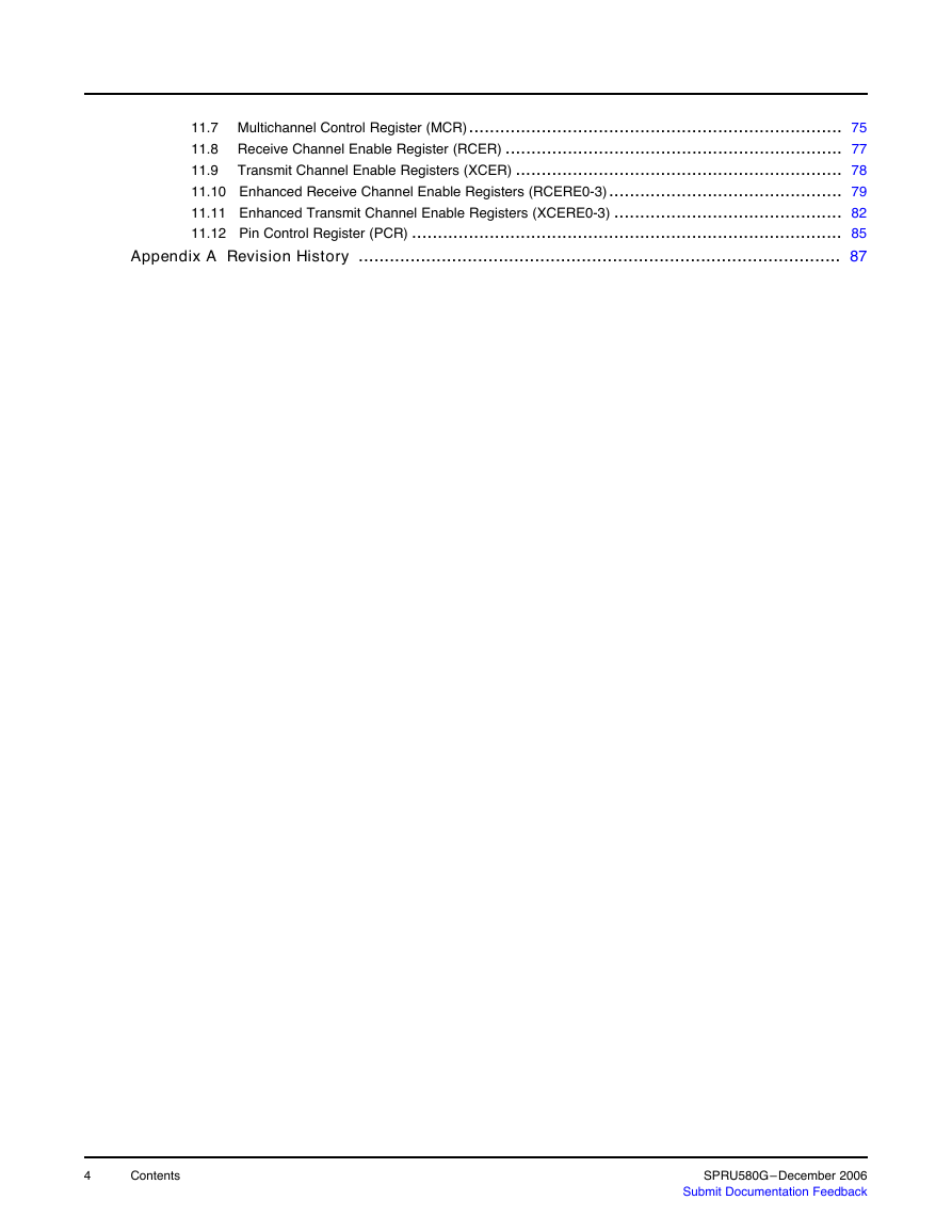
11.7 Multichannel Control Register (MCR)........................................................................ 75 11.8 Receive Channel Enable Register (RCER) ................................................................. 77 Transmit Channel Enable Registers (XCER) ............................................................... 78 11.9 11.10 Enhanced Receive Channel Enable Registers (RCERE0-3)............................................. 79 11.11 Enhanced Transmit Channel Enable Registers (XCERE0-3) ............................................ 82 11.12 Pin Control Register (PCR) ................................................................................... 85 Appendix A Revision History ............................................................................................. 87 4 Contents SPRU580G–December 2006 Submit Documentation Feedback
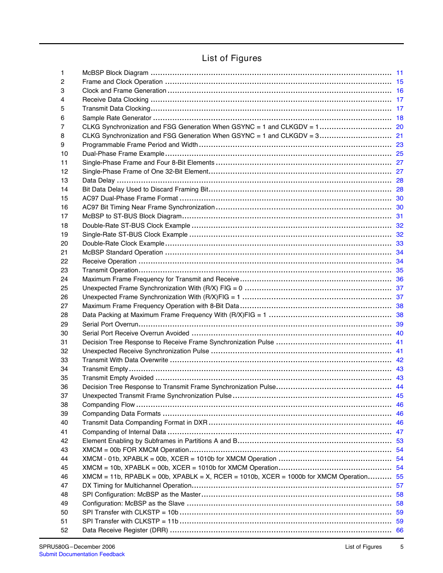
List of Figures McBSP Block Diagram .................................................................................................... 11 Frame and Clock Operation .............................................................................................. 15 Clock and Frame Generation ............................................................................................. 16 Receive Data Clocking .................................................................................................... 17 Transmit Data Clocking.................................................................................................... 17 Sample Rate Generator ................................................................................................... 18 CLKG Synchronization and FSG Generation When GSYNC = 1 and CLKGDV = 1.............................. 20 CLKG Synchronization and FSG Generation When GSYNC = 1 and CLKGDV = 3.............................. 21 Programmable Frame Period and Width................................................................................ 23 Dual-Phase Frame Example.............................................................................................. 25 Single-Phase Frame and Four 8-Bit Elements ......................................................................... 27 Single-Phase Frame of One 32-Bit Element............................................................................ 27 Data Delay .................................................................................................................. 28 Bit Data Delay Used to Discard Framing Bit............................................................................ 28 AC97 Dual-Phase Frame Format ........................................................................................ 30 AC97 Bit Timing Near Frame Synchronization......................................................................... 30 McBSP to ST-BUS Block Diagram....................................................................................... 31 Double-Rate ST-BUS Clock Example ................................................................................... 32 Single-Rate ST-BUS Clock Example .................................................................................... 32 Double-Rate Clock Example.............................................................................................. 33 McBSP Standard Operation .............................................................................................. 34 Receive Operation ......................................................................................................... 34 Transmit Operation......................................................................................................... 35 Maximum Frame Frequency for Transmit and Receive............................................................... 36 Unexpected Frame Synchronization With (R/X) FIG = 0 ............................................................. 37 Unexpected Frame Synchronization With (R/X)FIG = 1 .............................................................. 37 Maximum Frame Frequency Operation with 8-Bit Data............................................................... 38 Data Packing at Maximum Frame Frequency With (R/X)FIG = 1 ................................................... 38 Serial Port Overrun......................................................................................................... 39 Serial Port Receive Overrun Avoided ................................................................................... 40 Decision Tree Response to Receive Frame Synchronization Pulse ................................................ 41 Unexpected Receive Synchronization Pulse ........................................................................... 41 Transmit With Data Overwrite ............................................................................................ 42 Transmit Empty............................................................................................................. 43 Transmit Empty Avoided .................................................................................................. 43 Decision Tree Response to Transmit Frame Synchronization Pulse................................................ 44 Unexpected Transmit Frame Synchronization Pulse.................................................................. 45 Companding Flow .......................................................................................................... 46 Companding Data Formats ............................................................................................... 46 Transmit Data Companding Format in DXR............................................................................ 46 Companding of Internal Data ............................................................................................. 47 Element Enabling by Subframes in Partitions A and B................................................................ 53 XMCM = 00b FOR XMCM Operation.................................................................................... 54 XMCM - 01b, XPABLK = 00b, XCER = 1010b for XMCM Operation ............................................... 54 XMCM = 10b, XPABLK = 00b, XCER = 1010b for XMCM Operation............................................... 54 XMCM = 11b, RPABLK = 00b, XPABLK = X, RCER = 1010b, XCER = 1000b for XMCM Operation.......... 55 DX Timing for Multichannel Operation................................................................................... 57 SPI Configuration: McBSP as the Master............................................................................... 58 Configuration: McBSP as the Slave ..................................................................................... 58 SPI Transfer with CLKSTP = 10b ........................................................................................ 59 SPI Transfer with CLKSTP = 11b ........................................................................................ 59 Data Receive Register (DRR) ............................................................................................ 66 1 2 3 4 5 6 7 8 9 10 11 12 13 14 15 16 17 18 19 20 21 22 23 24 25 26 27 28 29 30 31 32 33 34 35 36 37 38 39 40 41 42 43 44 45 46 47 48 49 50 51 52 SPRU580G–December 2006 Submit Documentation Feedback List of Figures 5
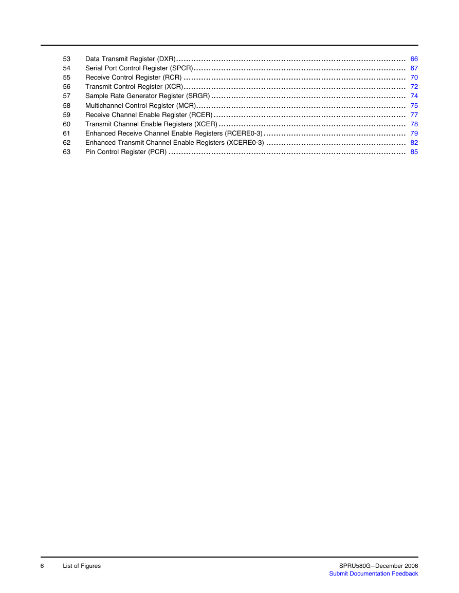
53 54 55 56 57 58 59 60 61 62 63 Data Transmit Register (DXR)............................................................................................ 66 Serial Port Control Register (SPCR)..................................................................................... 67 Receive Control Register (RCR) ......................................................................................... 70 Transmit Control Register (XCR)......................................................................................... 72 Sample Rate Generator Register (SRGR).............................................................................. 74 Multichannel Control Register (MCR).................................................................................... 75 Receive Channel Enable Register (RCER)............................................................................. 77 Transmit Channel Enable Registers (XCER)........................................................................... 78 Enhanced Receive Channel Enable Registers (RCERE0-3)......................................................... 79 Enhanced Transmit Channel Enable Registers (XCERE0-3) ........................................................ 82 Pin Control Register (PCR) ............................................................................................... 85 6 List of Figures SPRU580G–December 2006 Submit Documentation Feedback
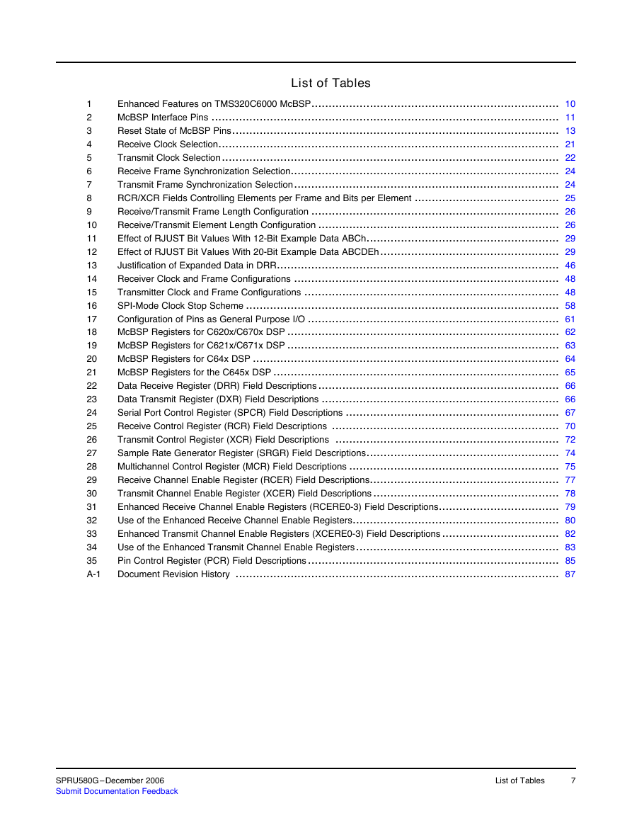
List of Tables Enhanced Features on TMS320C6000 McBSP........................................................................ 10 McBSP Interface Pins ..................................................................................................... 11 Reset State of McBSP Pins............................................................................................... 13 Receive Clock Selection................................................................................................... 21 Transmit Clock Selection.................................................................................................. 22 Receive Frame Synchronization Selection.............................................................................. 24 Transmit Frame Synchronization Selection............................................................................. 24 RCR/XCR Fields Controlling Elements per Frame and Bits per Element .......................................... 25 Receive/Transmit Frame Length Configuration ........................................................................ 26 Receive/Transmit Element Length Configuration ...................................................................... 26 Effect of RJUST Bit Values With 12-Bit Example Data ABCh........................................................ 29 Effect of RJUST Bit Values With 20-Bit Example Data ABCDEh.................................................... 29 Justification of Expanded Data in DRR.................................................................................. 46 Receiver Clock and Frame Configurations ............................................................................. 48 Transmitter Clock and Frame Configurations .......................................................................... 48 SPI-Mode Clock Stop Scheme ........................................................................................... 58 Configuration of Pins as General Purpose I/O ......................................................................... 61 McBSP Registers for C620x/C670x DSP ............................................................................... 62 McBSP Registers for C621x/C671x DSP ............................................................................... 63 McBSP Registers for C64x DSP ......................................................................................... 64 McBSP Registers for the C645x DSP ................................................................................... 65 Data Receive Register (DRR) Field Descriptions...................................................................... 66 Data Transmit Register (DXR) Field Descriptions ..................................................................... 66 Serial Port Control Register (SPCR) Field Descriptions .............................................................. 67 Receive Control Register (RCR) Field Descriptions .................................................................. 70 Transmit Control Register (XCR) Field Descriptions ................................................................. 72 Sample Rate Generator Register (SRGR) Field Descriptions........................................................ 74 Multichannel Control Register (MCR) Field Descriptions ............................................................. 75 Receive Channel Enable Register (RCER) Field Descriptions....................................................... 77 Transmit Channel Enable Register (XCER) Field Descriptions ...................................................... 78 Enhanced Receive Channel Enable Registers (RCERE0-3) Field Descriptions................................... 79 Use of the Enhanced Receive Channel Enable Registers............................................................ 80 Enhanced Transmit Channel Enable Registers (XCERE0-3) Field Descriptions .................................. 82 Use of the Enhanced Transmit Channel Enable Registers........................................................... 83 Pin Control Register (PCR) Field Descriptions......................................................................... 85 Document Revision History .............................................................................................. 87 1 2 3 4 5 6 7 8 9 10 11 12 13 14 15 16 17 18 19 20 21 22 23 24 25 26 27 28 29 30 31 32 33 34 35 A-1 SPRU580G–December 2006 Submit Documentation Feedback List of Tables 7
Preface SPRU580G–December 2006 Read This First About This Manual This document describes the operation of the multichannel buffered serial port (McBSP) in the digital signal processors (DSPs) of the TMS320C6000™ DSP family. Notational Conventions This document uses the following conventions. • Hexadecimal numbers are shown with the suffix h. For example, the following number is 40 hexadecimal (decimal 64): 40h. • Registers in this document are shown in figures and described in tables. – Each register figure shows a rectangle divided into fields that represent the fields of the register. Each field is labeled with its bit name, its beginning and ending bit numbers above, and its read/write properties below. A legend explains the notation used for the properties. – Reserved bits in a register figure designate a bit that is used for future device expansion. Related Documentation From Texas Instruments The following documents describe the C6000™ devices and related support tools. Copies of these documents are available on the Internet at www.ti.com. Tip: Enter the literature number in the search box provided at www.ti.com. The current documentation that describes the C6000 devices, related peripherals, and other technical collateral, is available in the C6000 DSP product folder at: www.ti.com/c6000. SPRU731 — TMS320C62x DSP CPU and Instruction Set Reference Guide. Describes the CPU architecture, pipeline, instruction set, and interrupts for the TMS320C62x digital signal processors (DSPs) of the TMS320C6000 DSP family. The C62x DSP generation comprises fixed-point devices in the C6000 DSP platform. SPRU732 — TMS320C64x/C64x+ DSP CPU and Instruction Set Reference Guide. Describes the CPU architecture, pipeline, instruction set, and interrupts for the TMS320C64x and TMS320C64x+ digital signal processors (DSPs) of the TMS320C6000 DSP family. The C64x/C64x+ DSP generation comprises fixed-point devices in the C6000 DSP platform. The C64x+ DSP is an enhancement of the C64x DSP with added functionality and an expanded instruction set. SPRU733 — TMS320C67x/C67x+ DSP CPU and Instruction Set Reference Guide. Describes the CPU architecture, pipeline, instruction set, and interrupts for the TMS320C67x and TMS320C67x+ digital signal processors (DSPs) of the TMS320C6000 DSP platform. The C67x/C67x+ DSP generation comprises floating-point devices in the C6000 DSP platform. The C67x+ DSP is an enhancement of the C67x DSP with added functionality and an expanded instruction set. SPRU190 — TMS320C6000 DSP Peripherals Overview Reference Guide. Provides an overview and briefly describes the peripherals available on the TMS320C6000 family of digital signal processors (DSPs). SPRU197 — TMS320C6000 Technical Brief. Provides an introduction to the TMS320C62x and TMS320C67x digital signal processors (DSPs) of the TMS320C6000 DSP family. Describes the CPU architecture, peripherals, development tools and third-party support for the C62x and C67x DSPs. SPRU395 — TMS320C64x Technical Overview. Provides an introduction to the TMS320C64x digital signal processors (DSPs) of the TMS320C6000 DSP family. 8 Preface SPRU580G–December 2006 Submit Documentation Feedback
分享到:
收藏