Copyright and Trademark Notices
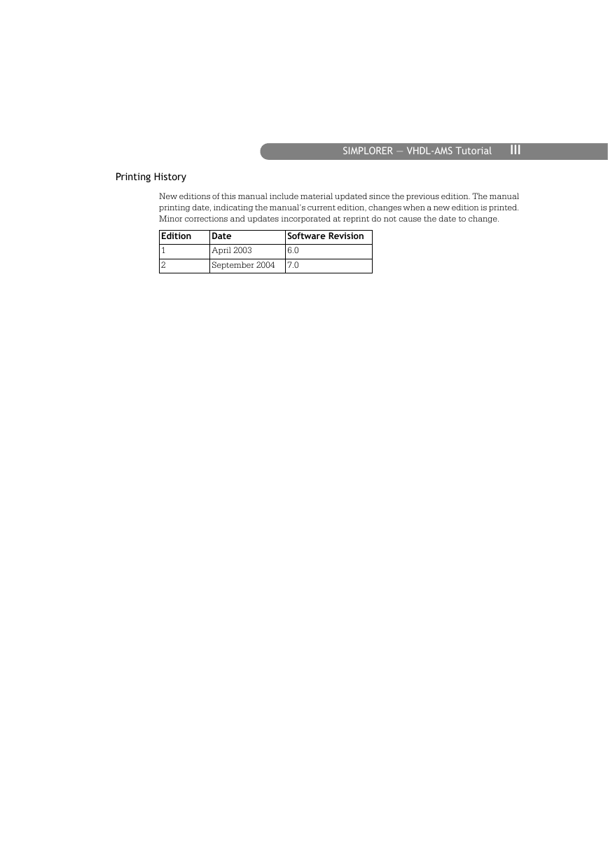
Printing History
Welcome
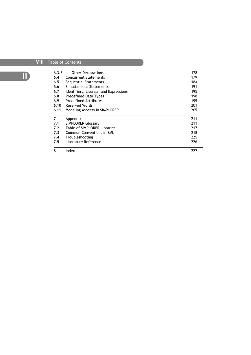
Table of Contents
General Description of Content
1 Introduction
2 VHDL-AMS and VHDL Models in SIMPLORER
3 Automotive Powernet System Example
4 Case Studies
5 Model Development
6 VHDL-AMS Short Reference/Language Fundamentals
7 Appendix
8 Index
1 Introduction
Content of the Tutorial
Tutorial Content on the Student Version CD
VHDL-AMS Tutorial Conventions
SIMPLORER Documentation
Printed Manuals
Online Help
Installing SIMPLORER
Hardware and Software Requirements
Installation under Windows 2000 and Windows XP
Starting Setup
SIMPLORER Version Size Limits
Starting the Simulation System SIMPLORER
Creating a New Project and Starting SIMPLORER Schematic
Creating a New Project
Schematic Window
SIMPLORER WebUpdates
2 VHDL-AMS Models in SIMPLORER
This chapter contains information on:
2.1 Using VHDL-AMS Models
Across and Through Quantities of Natures
Load Reference Arrow System
Packages and Models in Libraries
Entities and Architectures of VHDL-AMS Models
Capacitor
Nonlinear Capacitor
Placing and Connecting Models
Using Transformation Models
Defining Model Properties
Using Parameter Names
2.2 Displaying Results
Selecting Model Outputs
2D Digital Graph
Channels Tab
X-Axis Tab
Y-Axis Tab
Presentation Tab
3 Automotive Powernet System Example
This chapter contains information on:
Model Overview
Using Example Sheets
Creating Examples from Scratch
VHDL-AMS Modeling Features
3.1 Step 1: Alternator
Creating the Simulation Model
Overview of Parameter Values
Alternator Model
Entity Description
Architecture Description
Results
3.2 Step 2: Battery
Creating the Simulation Model
Overview of Parameter Values
Battery Model
Entity Description
Architecture Description
Results
3.3 Step 3: DC-DC Converter
Creating the Simulation Model
Overview of Parameter Values
DC-DC Converter
Entity Description
Architecture Description
Results
3.4 Step 4: Ignition Switch and Loads
Defining Simulation Model
Overview of Parameter Values
Ignition Switch Model
Entity Description
Architecture Description
Results
3.5 Step 5: Configuration Modes
Control Panel
Entity Description
Architecture Description
Using Configuration Files
Creating Configuration Files
Loading Configurations
Results
3.6 Step 6: Powertrain
Creating the Simulation Model
Overview of Parameter Values
Powertrain Model
Entity Description
Architecture Description
Results
4 Case Studies
This chapter contains information on:
Using Example Sheets
VHDL-AMS Modeling Features
4.1 Different Modeling Styles: Battery
Concepts
Graphical Modeling Style
Structural Modeling Style
Behavioral Modeling Style
Background
Model Style 1: Graphical Description
Model Style 2: Structural Description
Entity Description
Architecture Description
Model Style 3: Behavioral Description
Entity Description
Architecture Description
Results
4.2 Automated Model Development Using VHDL-AMS Wizard: Fuse
Concepts
Using the VHDL-AMS Wizard
Fuse Model Equivalent
Create a VHDL-AMS Framework for the Fuse Model
Describe the Entity
Describe the Architecture
Import the Model into Schematic
Animating the Model Symbol
Background: Fuse for Lamps in an Automotive Subsystem
Model: Digital Control Model
Entity Description
Architecture Description
Model Parameters
Simulation Parameters
Results
4.3 Detailed and Average Model Development: Claw-Pole Alternator
Concepts
Background: Detailed Model of a Claw-Pole Alternator
Model: Mathematical Claw-Pole Model
Results
Background: Averaged Model of Claw-Pole Alternator
Model
Speed-Voltage Model
Stator-Impedance Model
Results
4.4 Multilevel Modeling Techniques: Loads
Concepts
Background
Model: Load
Entity Description
Architecture Description: Admittance Load
Results
Architecture Description: Nominal Load
Results
Architecture Description: Switched Load
Results
Model: Lamp
Entity Description
Architecture Description
Results
Symbol Animation
4.5 Multidomain System Modeling: Linear Drive System, Solenoid
Concepts
4.5.1 Linear Drive System
Background
Model: Motor
Entity Description
Architecture Description
Model: Gearbox
Entity Description
Architecture Description
Results
4.5.2 Solenoid System
Background
Model: VHDL-AMS Solenoid
Entity Description
Architecture Description
Results
4.6 Mixed-Signal Modeling: DC-DC Model with PWM, Automotive Alarm System
Concepts
4.6.1 DC-DC Model
Background
Model: PWM Controller
Entity Description
Architecture Description
Results
4.6.2 Automotive Alarm System
Background
Model: Simple Microswitch
Entity Description
Architecture Description
Model: Advanced Microswitch
Model: Stimulus Generator
Model: Digital Controller
Entity Description
Architecture Description
Results
VHDL-AMS Export
Exporting a VHDL-AMS Model
Foreign Models
5 Model Development
This chapter contains information on:
5.1 VHDL-AMS Subsheets in Schematic
Graphical and Text Subsheets
Graphical Subsheets
Text Subsheets
Creating Graphical Subsheets
Creating Text Subsheets in VHDL-AMS
Copying Subsheets
Duplicating Subsheets
Adding Subsheets to a Library
5.2 Library and Model Management in the ModelAgent
ModelAgent Working Window
Model Libraries and Models
Managing Model Libraries
Managing Models
SIMPLORER Language Support
Symbols in the ModelAgent
Model Symbols
5.3 Managing VHDL-AMS Models in the ModelAgent
Creating Model Libraries
Creating Models
Creating Models in VHDL-AMS in the ModelAgent
Creating a VHDL-AMS Model Manually
Creating a VHDL-AMS Model Using the VHDL-AMS Wizard
Symbol Functions and Options in the Model Text Tab
Modifying the Model Symbol
Adding VHDL-AMS Models to a Library
Model Properties
General Properties Tab
Files Tab
Simulation Tab
Conservative Nodes Tab
Non-Conservative Nodes Tab
Model Text Tab
Tolerance Tab
Parameter Sets Tab
Stress Tab
5.4 Managing VHDL-AMS Packages in the ModelAgent
Creating Packages in the ModelAgent
Creating a Package
Inserting a Package from an Existing .vhd File
Properties of Packages
General Tab
Package Text Tab
Package Body Text Tab
Compile Function
5.5 Simulator Environment
Models for VHDL-AMS Simulation
Parameters of VHDL-AMS Simulator
6 VHDL-AMS Language Fundamentals
This chapter contains information on:
6.1 Design Units
6.1.1 Entities and Architectures
Entity Declaration
Architecture
6.1.2 Packages
Package Declaration
Package Body
Package Visibility
VHDL-AMS Standard Packages and Types
STD Library
The IEEE Library
6.2 Subprograms
Procedures
Functions
6.3 Declarations
6.3.1 TYPE Declarations
Type Declarations
SUBTYPE Declaration
NATURE Declaration
6.3.2 Data Object Declarations
CONSTANT Declaration
SIGNAL Declaration
VARIABLE Declaration
FILE Declaration
QUANTITY Declaration
TERMINAL Declaration
6.3.3 Other Declarations
ATTRIBUTE Declaration
COMPONENT Declaration
6.4 Concurrent Statements
BLOCK Statement
PROCESS Statement
Concurrent Procedure Call Statement
Concurrent ASSERT Statement
Concurrent SIGNAL Assignment Statement
Component Instantiation Statement
BREAK Statement
6.5 Sequential Statements
WAIT Statement
ASSERT Statement
SIGNAL Assignment Statement
VARIABLE Assignment Statement
Procedure Call Statement
IF Statement
CASE Statement
LOOP Statements
NEXT Statement
EXIT Statement
RETURN Statement
NULL Statement
BREAK Statement
6.6 Simultaneous Statements
Simple Simultaneous Statement
Simultaneous IF Statement
Simultaneous CASE Statement
Simultaneous PROCEDURAL Statement
Simultaneous NULL Statement
6.7 Identifiers, Literals, and Expressions
Identifiers
Literals
Arithmetic and Logical Expressions
6.8 Predefined Data Types
Predefined VHDL-AMS Standard Data Types
Predefined Type Declarations
6.9 Predefined Attributes
Quantity Attributes
Signal Attributes
Data Type Bounds
Enumeration Data Types
Array Indexes for an Array A
6.10 Reserved Words
6.11 Modeling Aspects in SIMPLORER
Processes
Quantities, Signals, and Variables
Signal Assignments with Delay
Data Exchange in Mixed-Signal Models
Signal to Quantity Assignment (Digital to Analog)
Quantity to Signal Assignment (Analog to DIgital)
Solvability
WORK Library
Alias for File Names
Values on Sheet
Vector Inputs on Sheet
A Appendix
A.1 SIMPLORER Glossary
A.2 Table of SIMPLORER Libraries
A.3 Common Conventions in SML
Names of Components and Variables
Unit Suffixes of Numeric Data
SI Units
Parameter Qualifiers
Predefined Variables
Predefined Constants
Equations, Expressions, and Variables
Standard Mathematical Functions
Network Configurations
The following types of network configurations are invalid:
Actions in States
Basic Rules for Specifying Time Steps
A.4 Troubleshooting
Modeling
Display and Simulation
A.5 Literature Reference
Index


 2023年江西萍乡中考道德与法治真题及答案.doc
 2012年重庆南川中考生物真题及答案.doc
 2013年江西师范大学地理学综合及文艺理论基础考研真题.doc
 2020年四川甘孜小升初语文真题及答案I卷.doc
 2020年注册岩土工程师专业基础考试真题及答案.doc
 2023-2024学年福建省厦门市九年级上学期数学月考试题及答案.doc
 2021-2022学年辽宁省沈阳市大东区九年级上学期语文期末试题及答案.doc
 2022-2023学年北京东城区初三第一学期物理期末试卷及答案.doc
 2018上半年江西教师资格初中地理学科知识与教学能力真题及答案.doc
 2012年河北国家公务员申论考试真题及答案-省级.doc
 2020-2021学年江苏省扬州市江都区邵樊片九年级上学期数学第一次质量检测试题及答案.doc
 2022下半年黑龙江教师资格证中学综合素质真题及答案.doc